The DJ Jeep came with a set of new in box shocks. The ones on the Jeep where out of gas. I dunno how long these old new in box shocks will last but they are at least working for now.
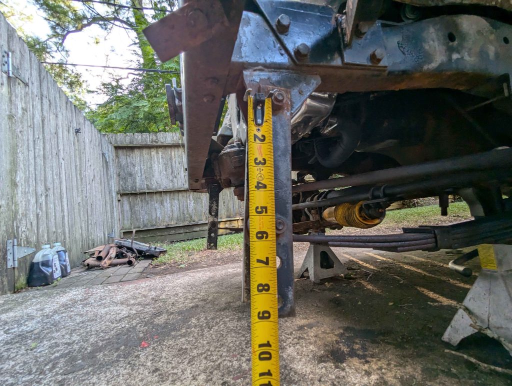
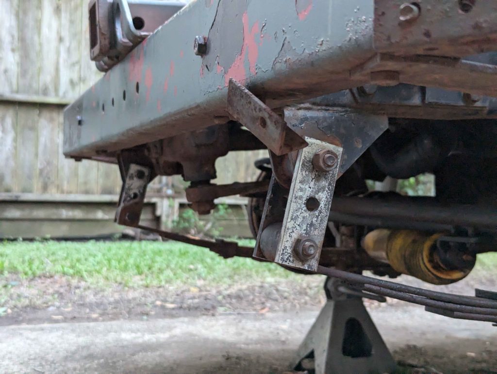
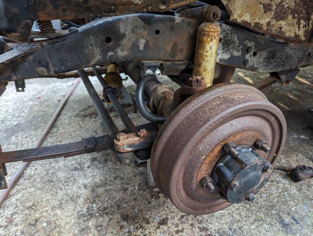
What is weird about the suspension is that the front shackles have been replaced at one point with lifting shackles.
The previous owner mentioned that this Jeep was once used as a boat ramp launching vehicle and suspected that these longer shackles where installed to prevent the suspension from bottoming out.
I dunno if this is true about the DJ Jeeps but every Jeep I have worked on, the front and rear shackles for the leaf springs are the same length.
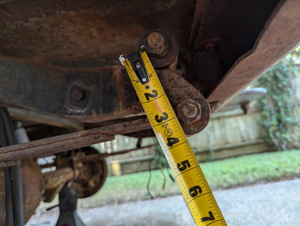
Rear shackle measures 3″ from bolt to bolt.
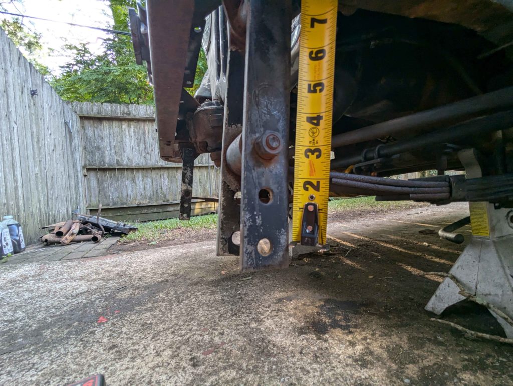
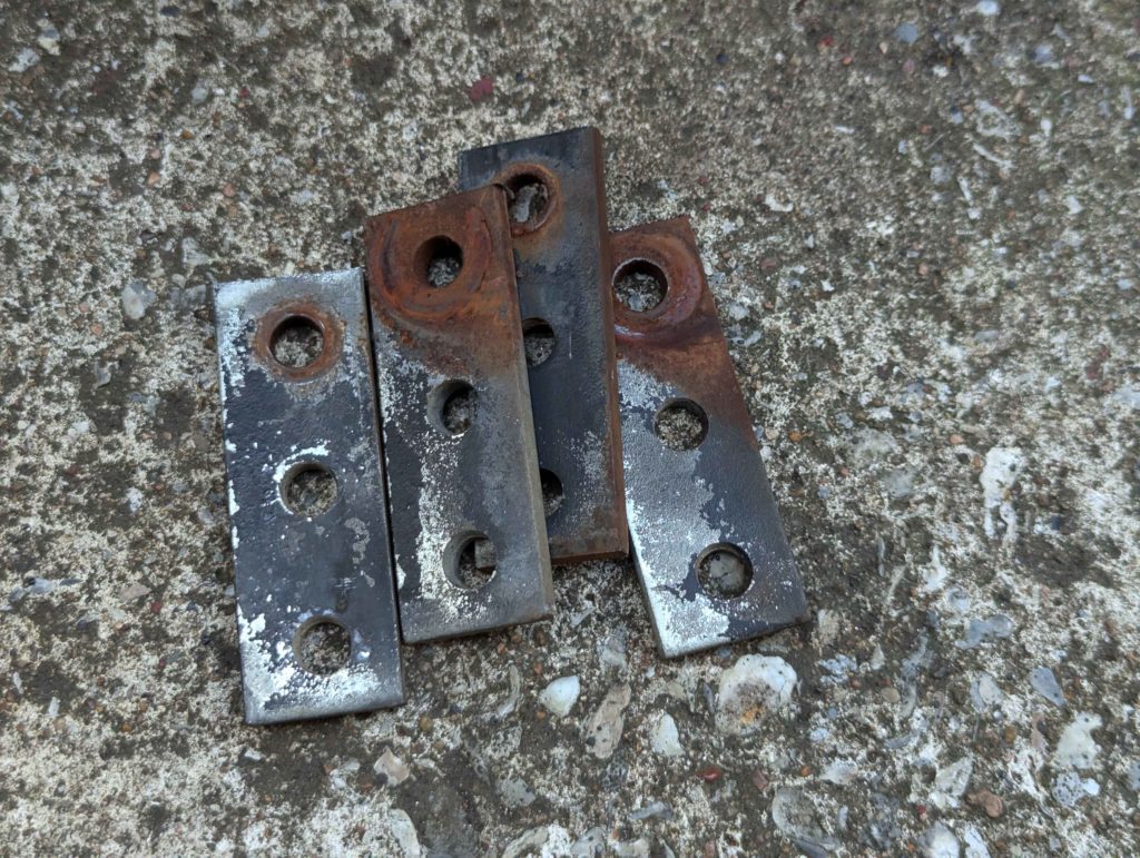
Here are the lift shackles. 5.5″ for a 2.5″ lift in the front. What is interesting is the bottom holes for adjustment.
The holes are 1.5″ spaced so I can cut these long shackles down and make a normal 3″ long pair.
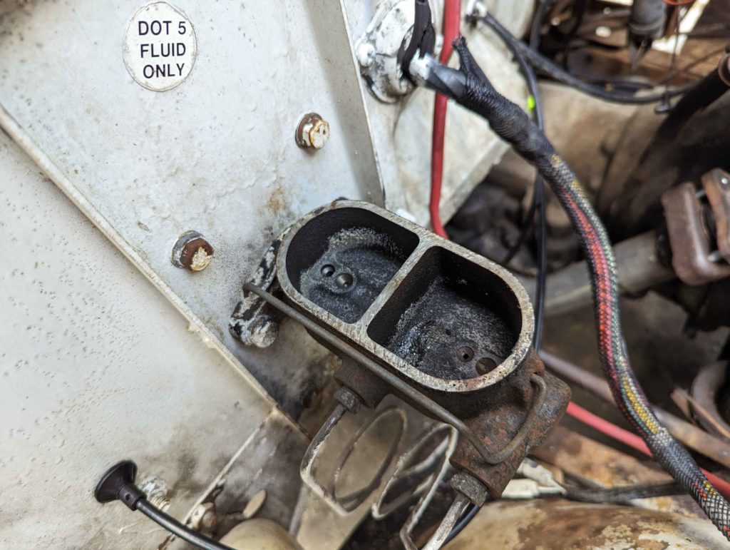
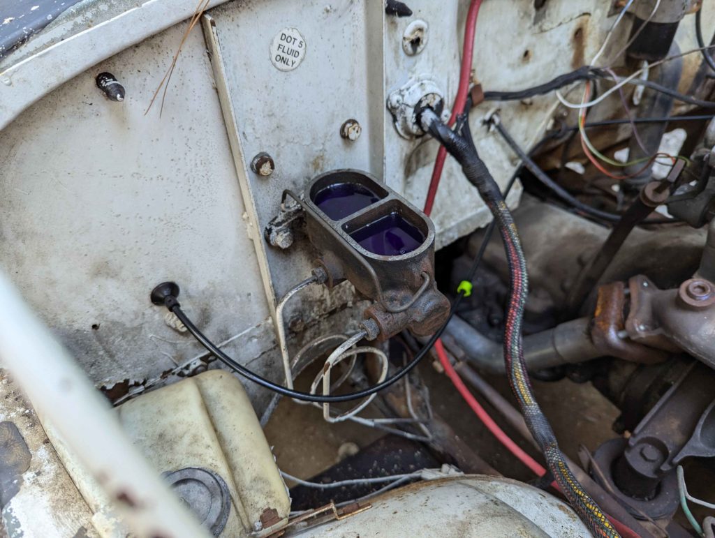
The DJ Jeep is a 4 drum, manual braking system. Very basic but it works well and with only 100 HP and 2200lbs of curb weight, the drum system will work fine. We are just going to rebuild what is there.
DOT 5! Interesting. DOT 5 is a silicon based fluid instead of the typical glycol based DOT 3, 4, 5.1 stuff. It has some interesting advantages over the glycol based fluid. DOT 5 does not absorb water like glycol based fluids, thus brake systems don’t rust out. Downsides are that it can’t be used in ABS systems. Both are not compatible with each other so we should stick with DOT 5. Maybe future car builds I should switch to DOT 5… I mean look at that master cylinder, just some dried out silicon fluid, no rust!
I cleaned out the master cylinder with some denatured alcohol and then flushed the entire system with the denatured alcohol. This gets rid of any residue and water that may be in the lines. I then took all the soft brake lines out and used compressed air to blow out the rest of the alcohol.
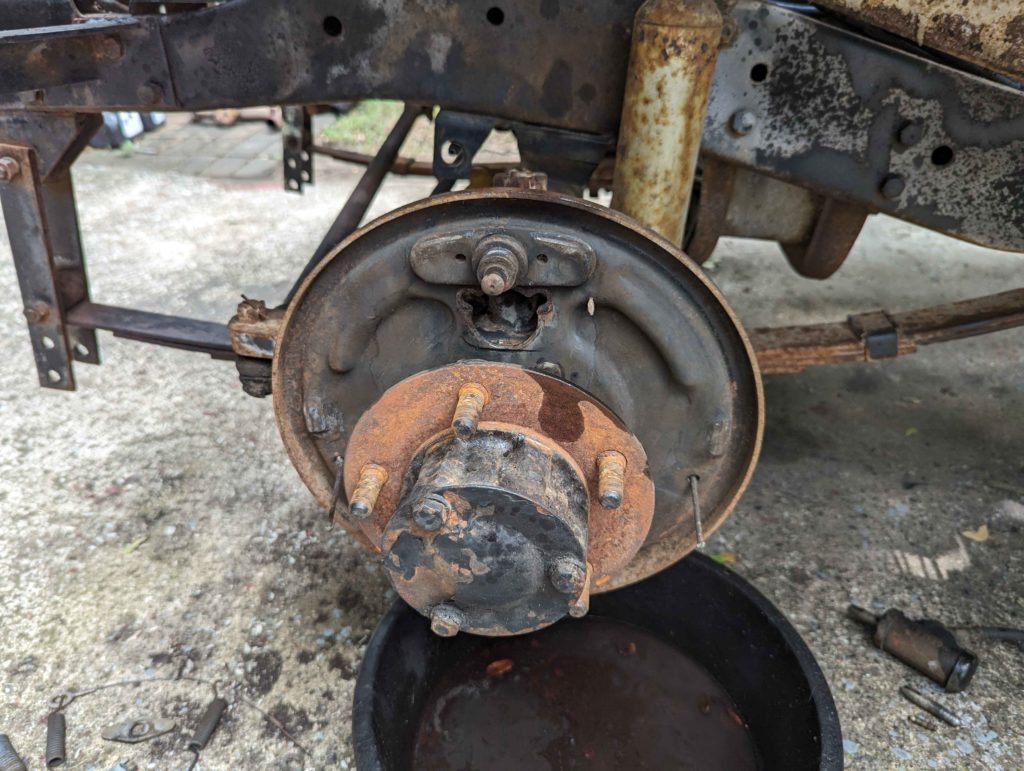
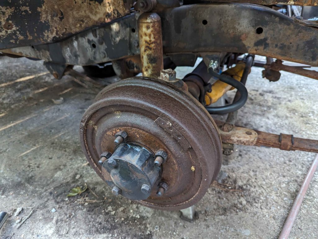
I then popped the drums off the brakes with a drum puller. Highly recommend getting a drum puller like an Astro 78830.
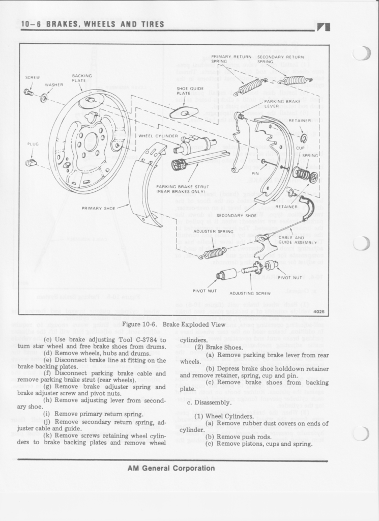
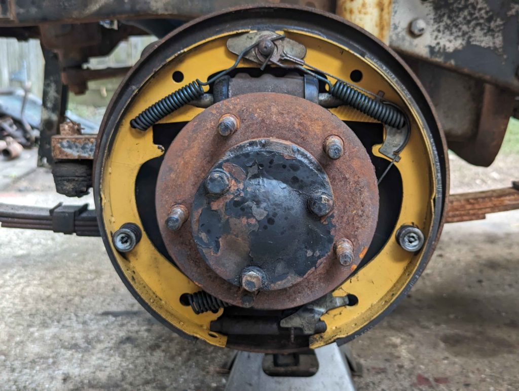
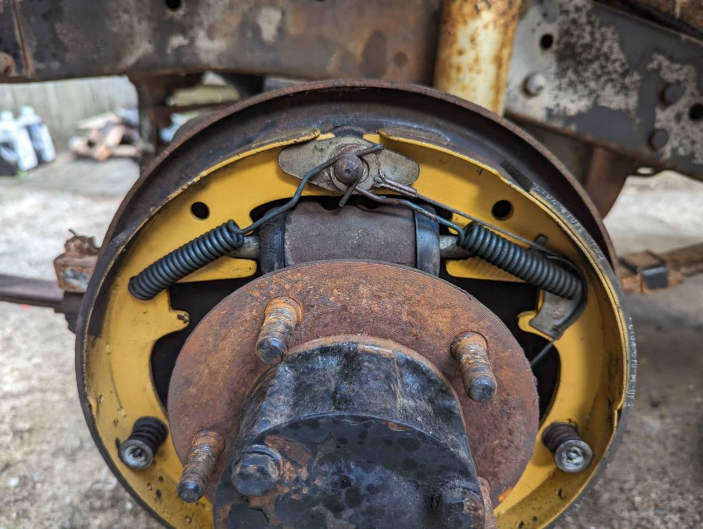
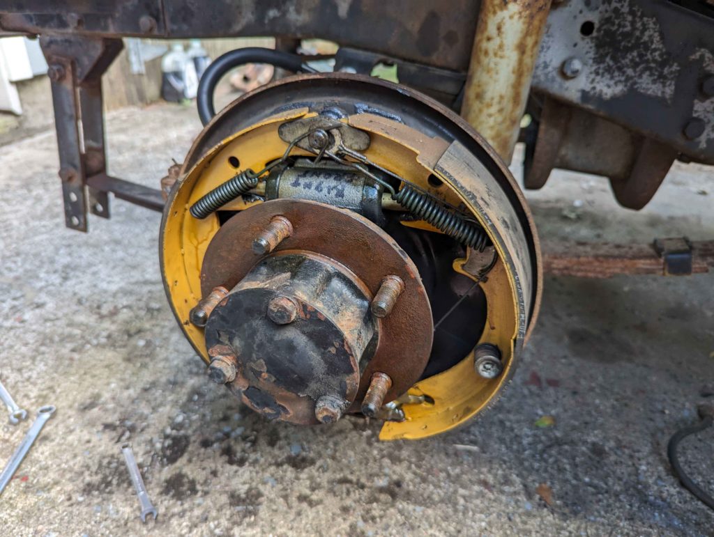
This is what the brakes look like before disassembly. Make sure to take pictures!
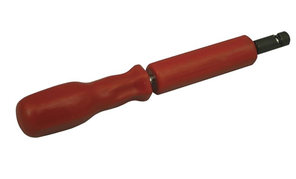
To easily remove the springs get a Lisle 44800 Heavy-Duty Brake Spring Tool.
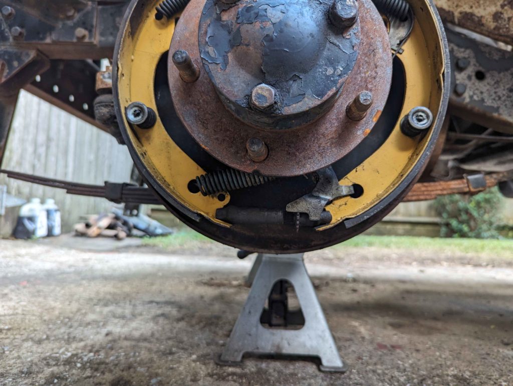
It screws onto the springs and grips them. I find it easier to remove the bottom spring first and then the top 2 springs on drums. After disassembly, clean all the parts with brake clean. Replace the drum cylinder with a new one and install a new rubber line. On all the surfaces where metal rubs on metal, apply some brake grease, don’t need a lot.
Reassembly is reverse of how it came apart. Make sure that self adjusting cable goes on correctly. Put the top two springs on before the bottom spring seemed to be the easiest way.
The outside of the drums I hit with a wire brush to knock off surface rust and then hit them with an anti corrosion spray. It will eventually bake off but atleast keeps them from rusting more for now. I want to eventually paint these drums.
Then fill and bleed the system with fresh DOT 5. This DOT 5 fluid had a dye in it so it was easy to know that the rest of the alcohol was flushed out when the purple DOT 5 fluid showed up in the vacuum bleeder.
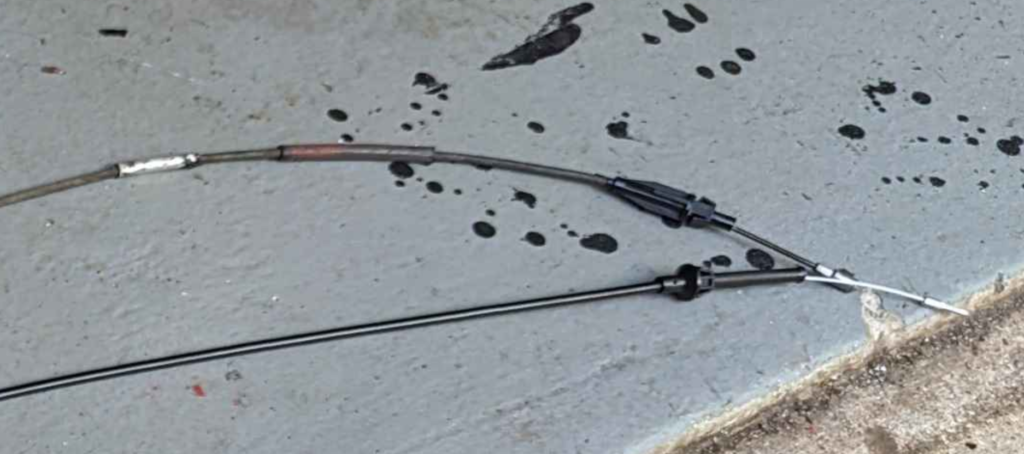
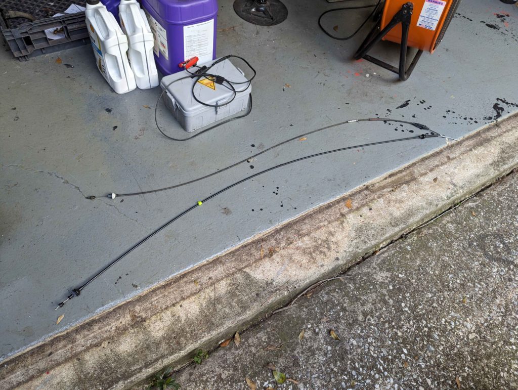
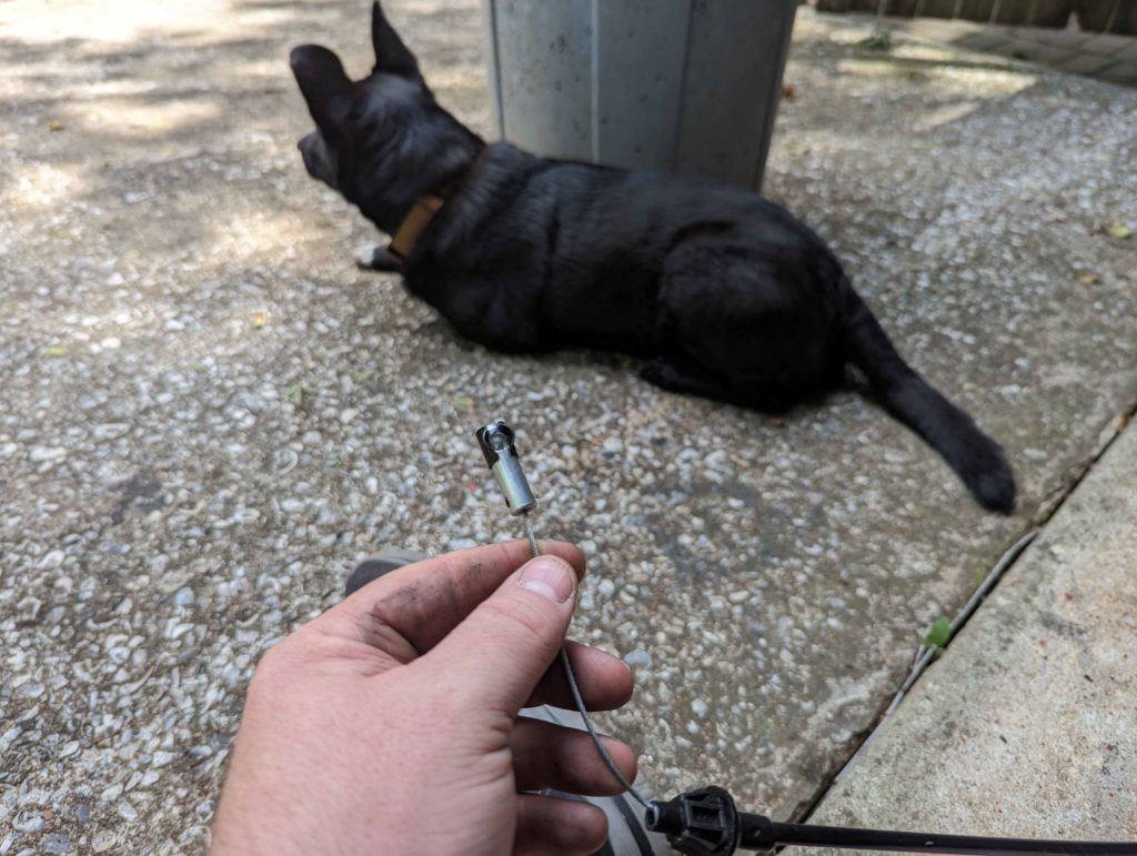
The throttle cable on the DJ was previously damaged and been repaired a couple times. This is causing the cable to grab and not allow the carburetor to close.
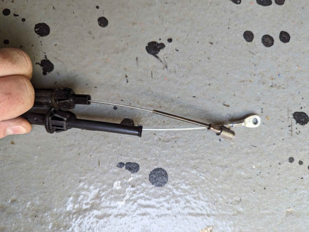
The replacement cable I was able to find was close in length but needed a different end for the carburetor.
Cut off the original end and put on this ball end for the cable. This just clips onto the carburetor.
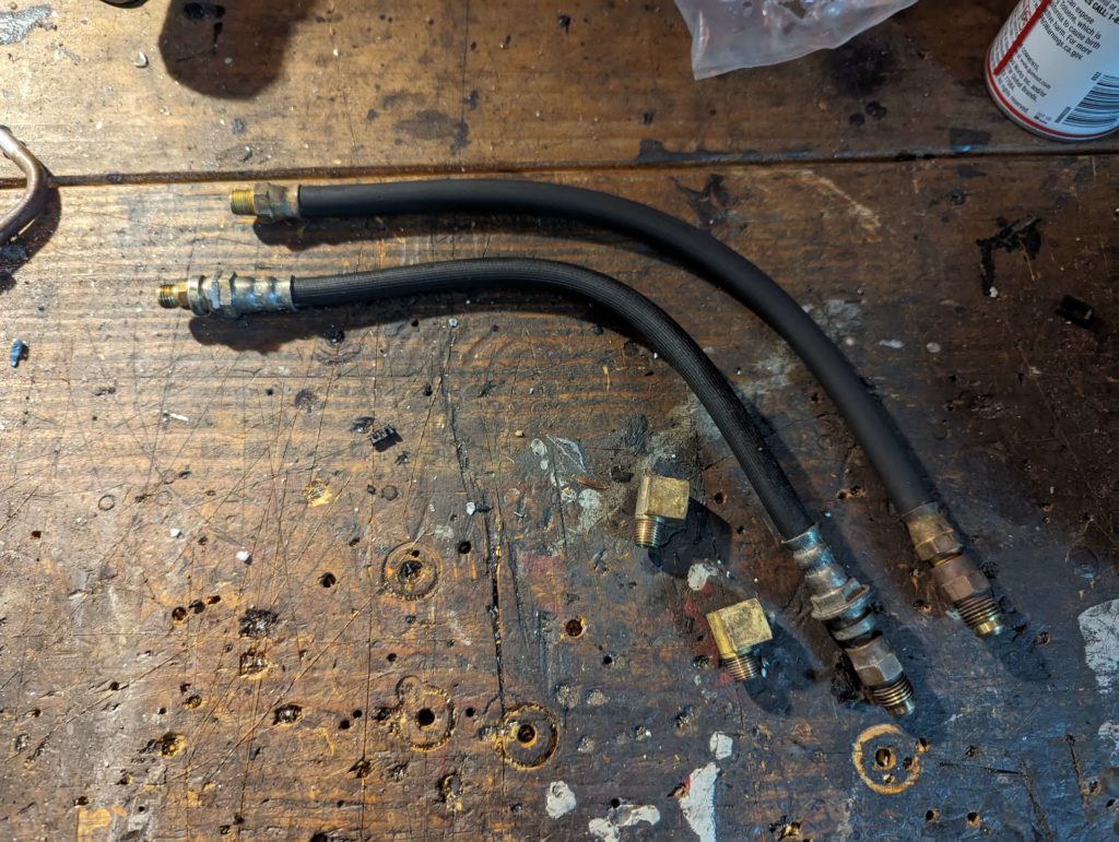
Since I replaced the radiator, the transmission cooler lines needed to be removed. I dunked these in the ultrasonic cleaner to get the grunge off.
One of these lines is not like the other! A line was made from a converted brake line. The rubber of that hose was all gummy and starting to fall apart. I ended up replacing it with some barb fittings and a piece of transmission cooler hose.
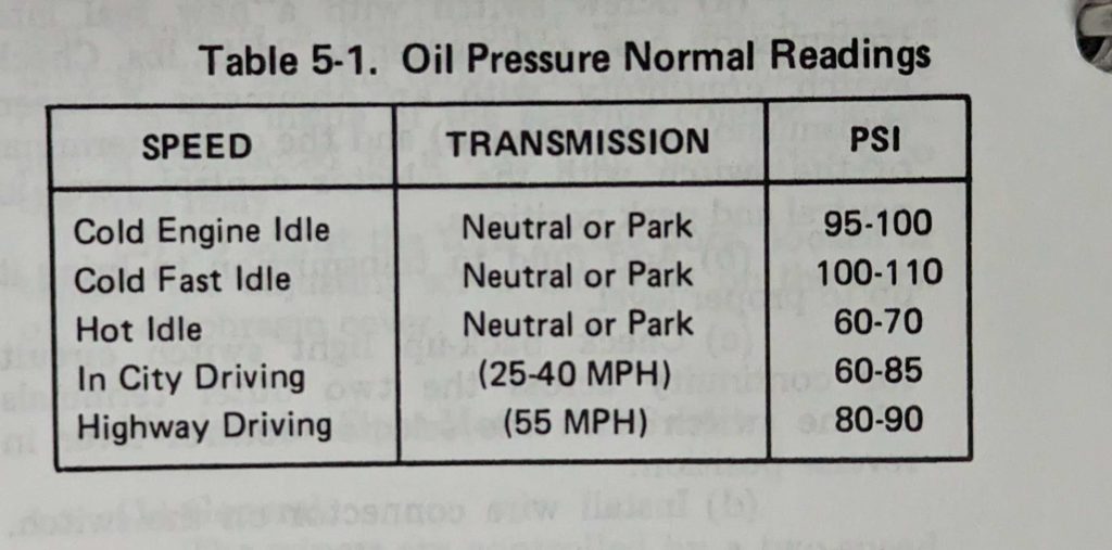
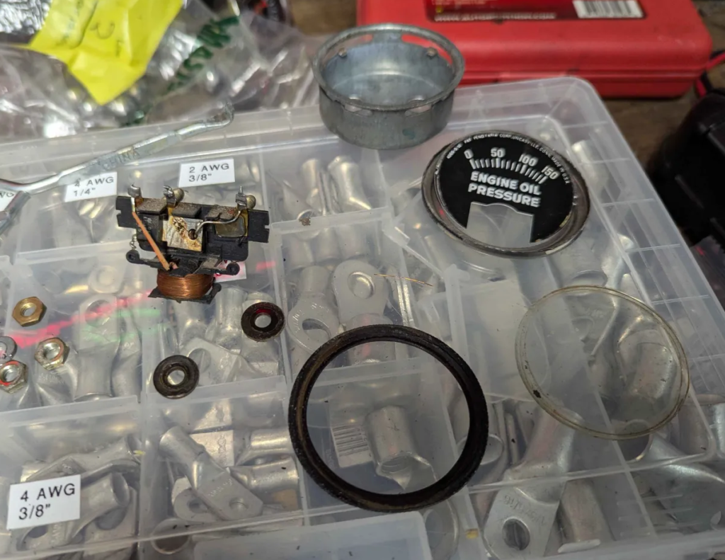
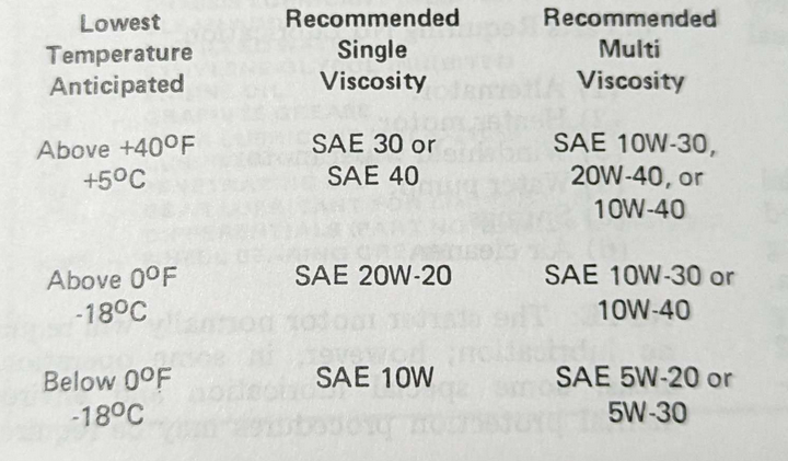
I noticed while running the engine, that the oil pressure gauge never seemed to move once running. It was sitting at ~30-40lbs of pressure. I read on Porsche 924 forums that the oil pressure of these engines is supposed to be high. Looking in the service manual we have.
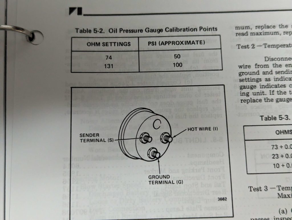
Cold idle should be around 100 PSI! 30 is much too low. But before figuring out if there was an oil problem or bearing problem, lets just check the gauge and sender. The gauges on this jeep are old and probably way out of calibration.
Measuring the sensor off the back of the engine with a multimeter I was reading ~140ohms at cold idle. The service manual has a way to calibrate the oil pressure gauge and specifies two points.
So 140ohms would be around 110psi. Looks like the engine is happy with oil pressure! Will have to figure out what is up with the gauges. I am betting that the ground for the dash has a bad connection.
It ended up just being some dirt in the gauge preventing the needle from moving.
The original radiator looks to have been clearanced with the cooling fan at one point, the seal at the top of the tank is split, and the brackets are pretty rusted.
Instead of trying to fix up the original radiator, I looked for a replacement. The DJ doesn’t share a radiator with the CJ chassis of Jeeps. The front opening is smaller on the DJ. A couple companies make replacement radiators but not for the DJ-5G. The Audi engine flipped the sides for the intake and outtake for the radiator and was the only engine for the DJ that was like this. Safe to say, no one makes a direct replacement for the G model.
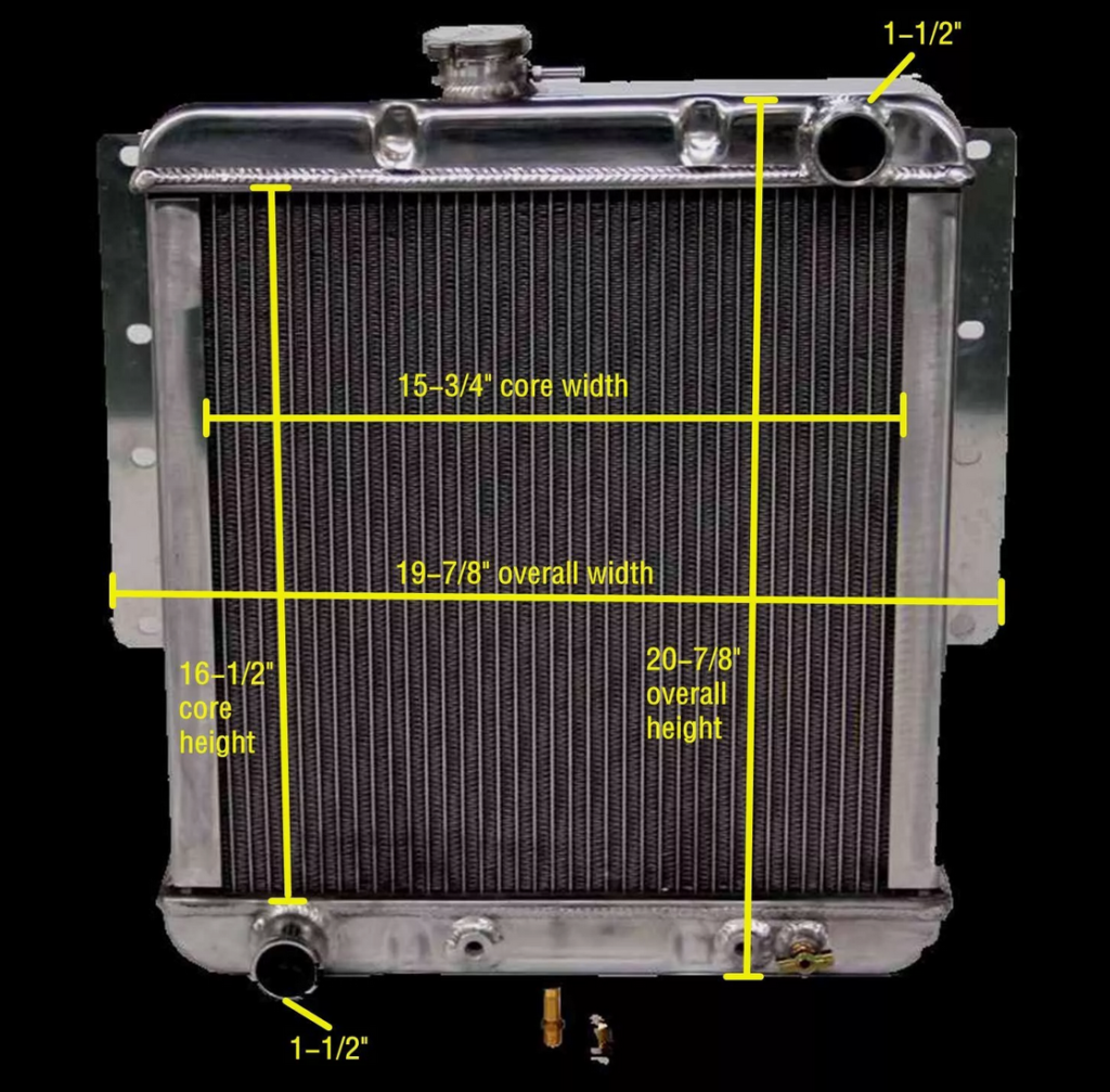
So I ordered a radiator for the other models of the DJ that is made by “KKS”. If you search around for “KKS 3 ROW ALLALUMINUM RADIATOR FIT 1966-1974 Jeep DJ5 CAR 1966-1974 3.8L 4.2L” you will find it.
The radiator fit perfect into the opening but we need to hook it up!
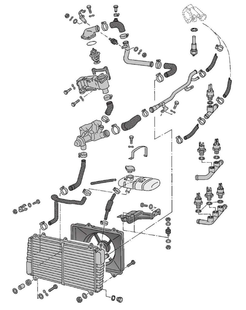
This is a diagram of the Porsche 924 cooling system.
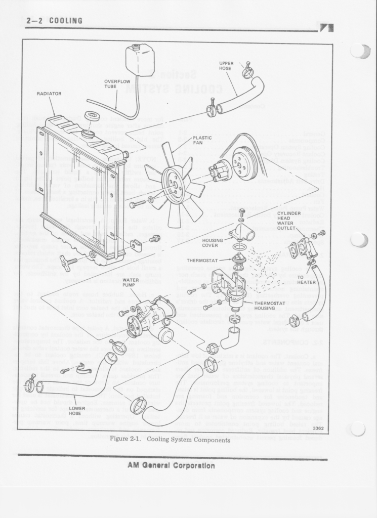
And this is the cooling diagram for the DJ-5G. I wanted to look at these cause the backside of the block has a coolant passage that then runs into the intake to heat up the fuel mixture.
The lower radiator hose was pretty easy to get hooked up with a Gates 25804 Vulco-Flex II Flexible Hose.
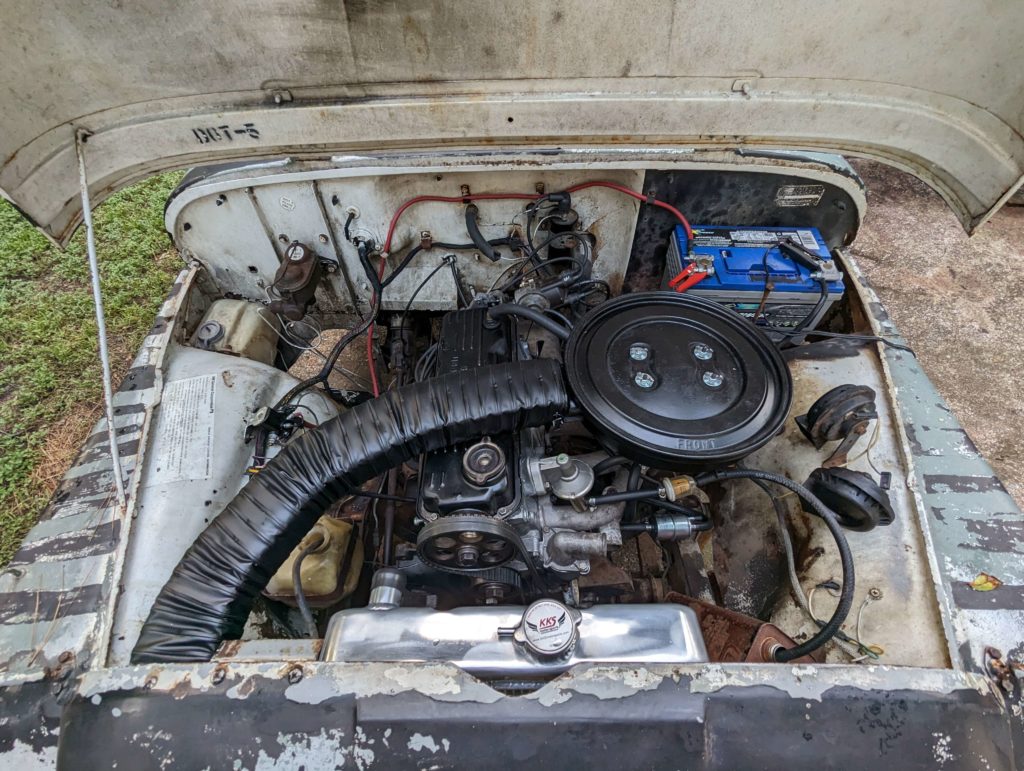
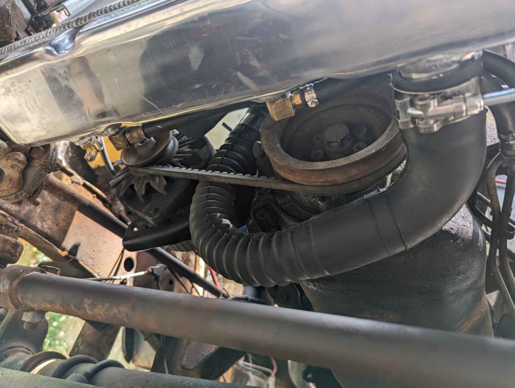
The back of the engine needed a hose block off and a some piece of heat core hose to get the intake heater hooked up.
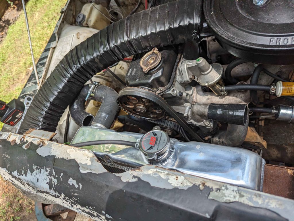
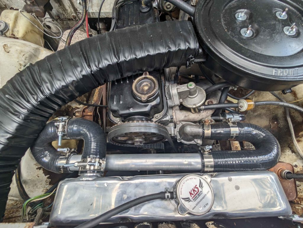
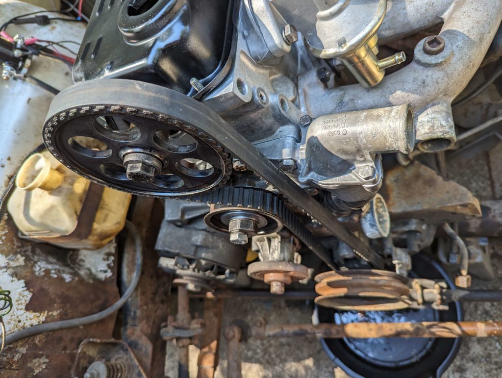
Now the upper radiator hose is more of a problem. The cog for the cam timing prevents turning directly right. We can’t send the radiator hose over the engine because that would bring it above the coolant system above the radiator cap and would make bleeding the system a pain. This makes the only option to go down and to the left.
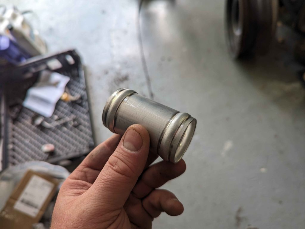
To join the hoses together, I cut some aluminum tubes and bead rolled them.
Now we can fill the system with coolant and bring the engine up to temperature. I set the idle and timing to 800 rpm with the transmission in drive with 10 degrees advanced. This is what the service manual specifies. The engine does seem to like a bit more advance.
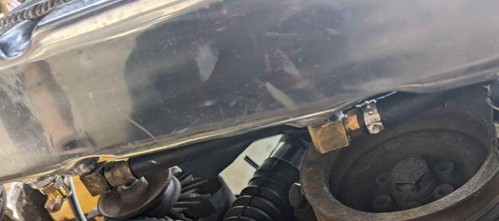
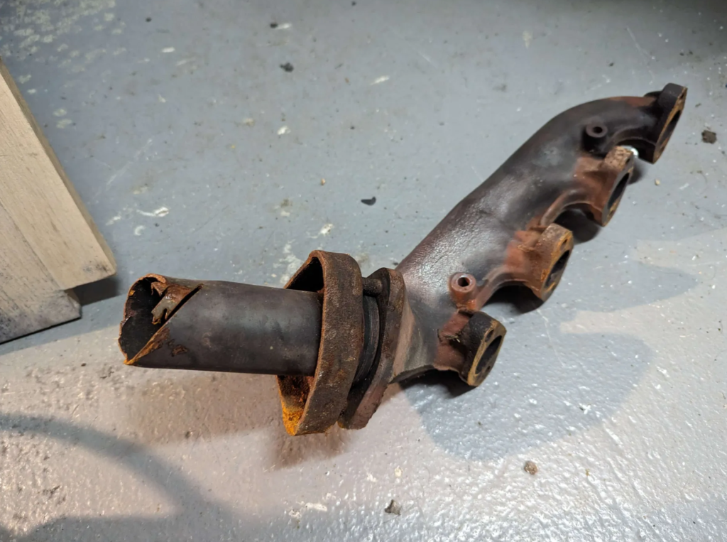
This is the exhaust system that I welded together for the DJ Jeep. The only original part is the “bell” part which connects to the exhaust manifold.
Its just 2″ mild steel exhaust tubing and a tiny muffler I had in my parts bin. I did a side exit right in front of the rear tire to make it easier to make and not require more bends then I had tubing for.
I then did an oil change, cleaned/gapped the spark plugs, and cleaned and adjusted the points in the distributor. Oil is 20W-50 STP and a Purolator PL20252 oil filter.
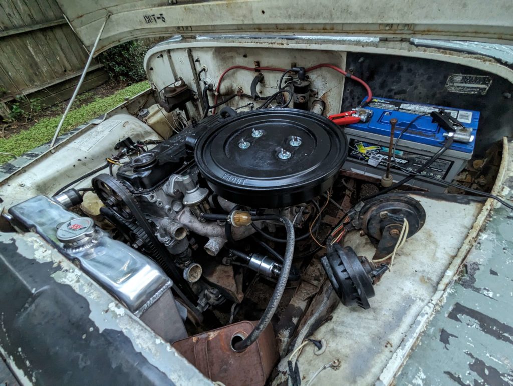
I then cleaned up the air cleaner with a wire brush to remove the rust and then threw on some semi-gloss black paint. The fuel system is starting to come together. Fuel filters and some tubing into a gas can :)
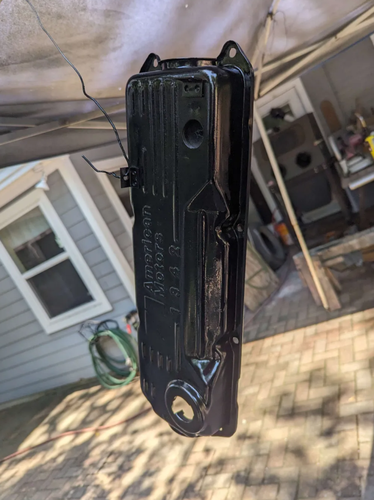
The leaky valve cover ended up being a leak from the mounting points for the timing belt cover. Interesting that its open to the oil system. A random bolt threaded in stopped the leak.
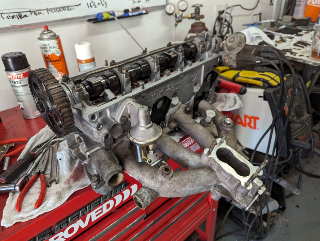
With the cylinder head “rebuilt” its time to install it back on the block. I am using a FEL-PRO HS 8647 PT-1 head gasket set which has all the seals for the top end of this engine.
For head bolts I just reused the original ones. The service manual doesn’t say if I need new ones or not. Of course Porsche 924 forums say you absolutely need new ones :)
The torque pattern is normal but the engine has a 2-step torque step. You bring the torque of the headbolts up to the first spec, 65 ft-lbs, and then you need to run the engine and heat it up and then retorque the head bolts and bring it up to 85 ft-lbs.
Also, you should set the valve lash at the same time as it is required to bring the engine up to temperature to set the lash correctly. You will need two valve cover gaskets to do this correctly. So order a FEL-PRO VS50175C valve cover gasket set along with the head gasket set.
However at this point, I set the valve lash to 0.007″ on the intake and 0.017″ on the exhaust which is the factory lash for cold.
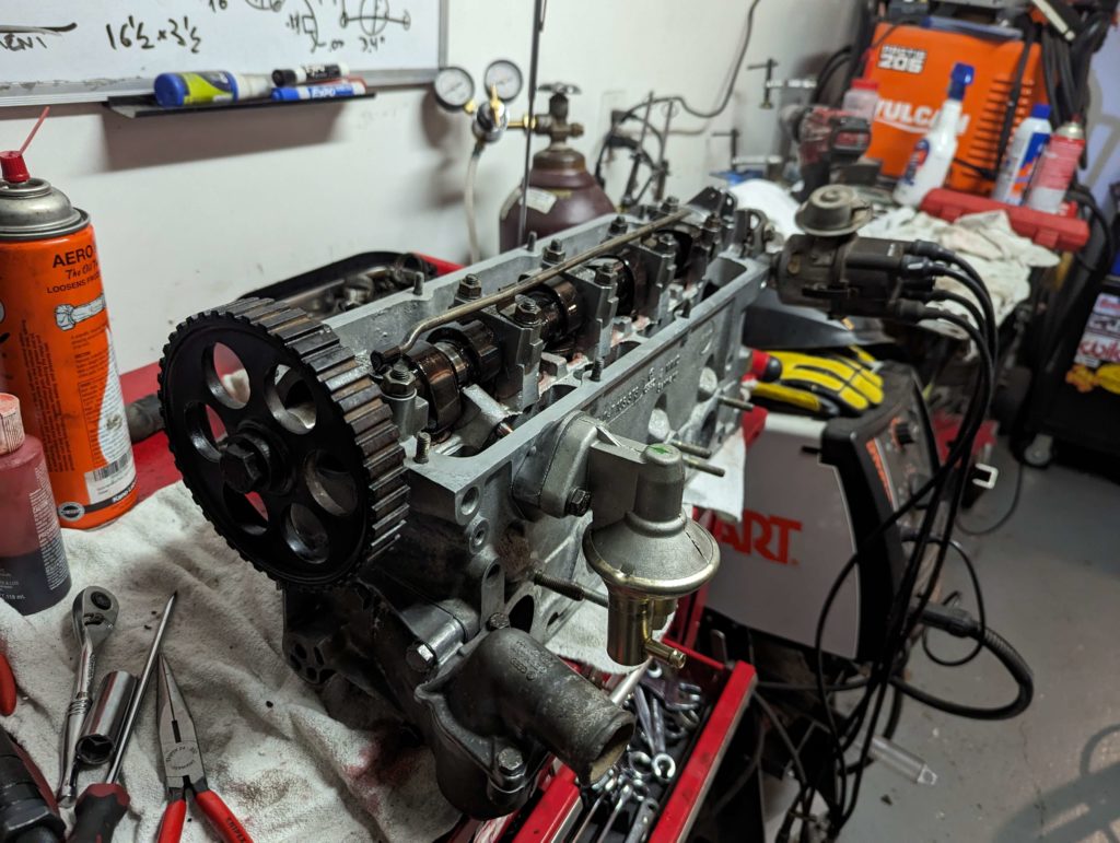
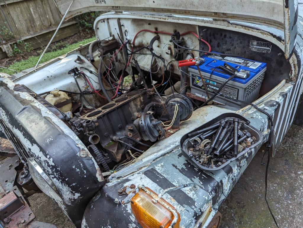
With the head and accessories installed, I set the timing of the cam gear and cylinder 1 being at top dead center. After checking everything out I tested the compression for each cylinder to see if we improved it.
Compression test:
150lbs
90lbs
85lbs !!!!
120lbs
From zero to 85lbs! Now this is no where near what it should be but should make it run better!
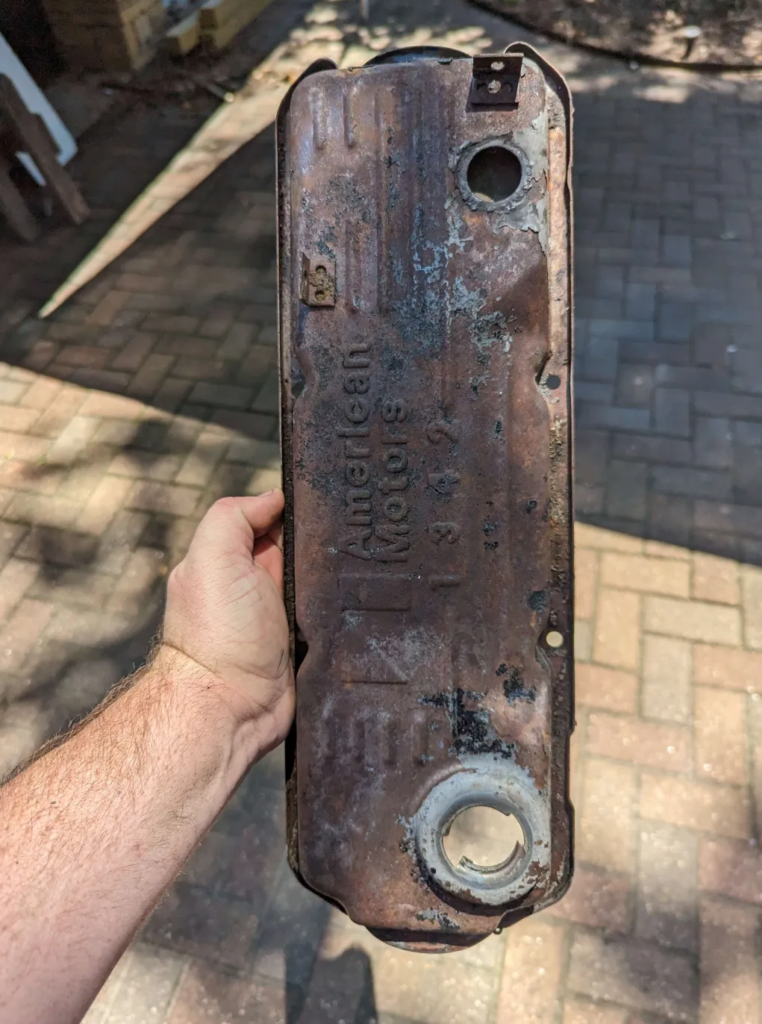
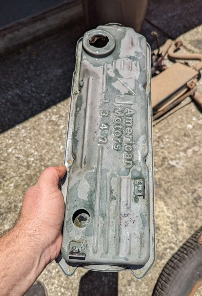
The valve cover looks pretty terrible so lets sand blast it and give it some fresh spray paint
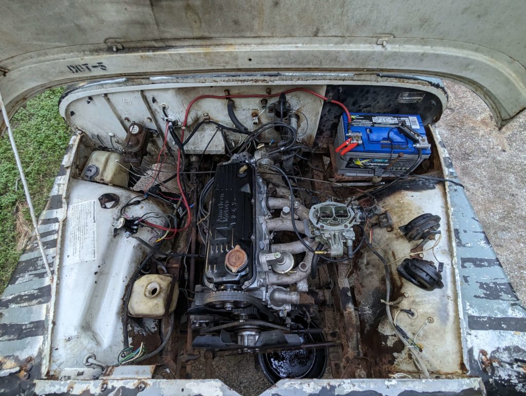
It runs! There is a weird oil leak up on the front of the valve cover but it runs and doesn’t backfire. It starts easy as well. I won’t be able to bring it up to temperature yet as I need to get the cooling system working before then.
After a couple rotations in the the ultrasonic cleaner the cylinder head cleaned up nice!
Still some stuck on grime down in the oil galleys but this will be perfectly acceptable for getting it running.
What a stark difference between how it started! The ultrasonic cleaner really does a great job.
I am not going to mic out and measure this cylinder block. Lets just assume its all good ;)
Just going to give the valves a lap to clean up the valve seats since that is what I think is wrong with cylinder 3.
Some 120 followed by 240 grit valve lapping compound and a power drill made short work of cleaning up the valve seats. I think we may get this engine to run!
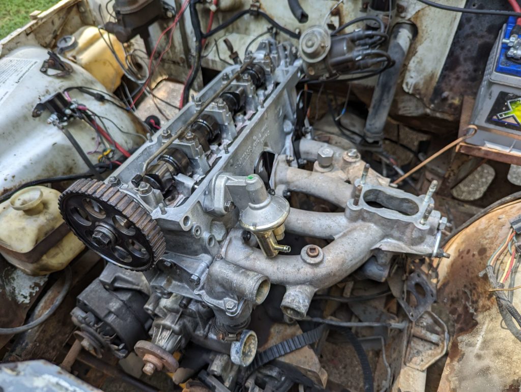
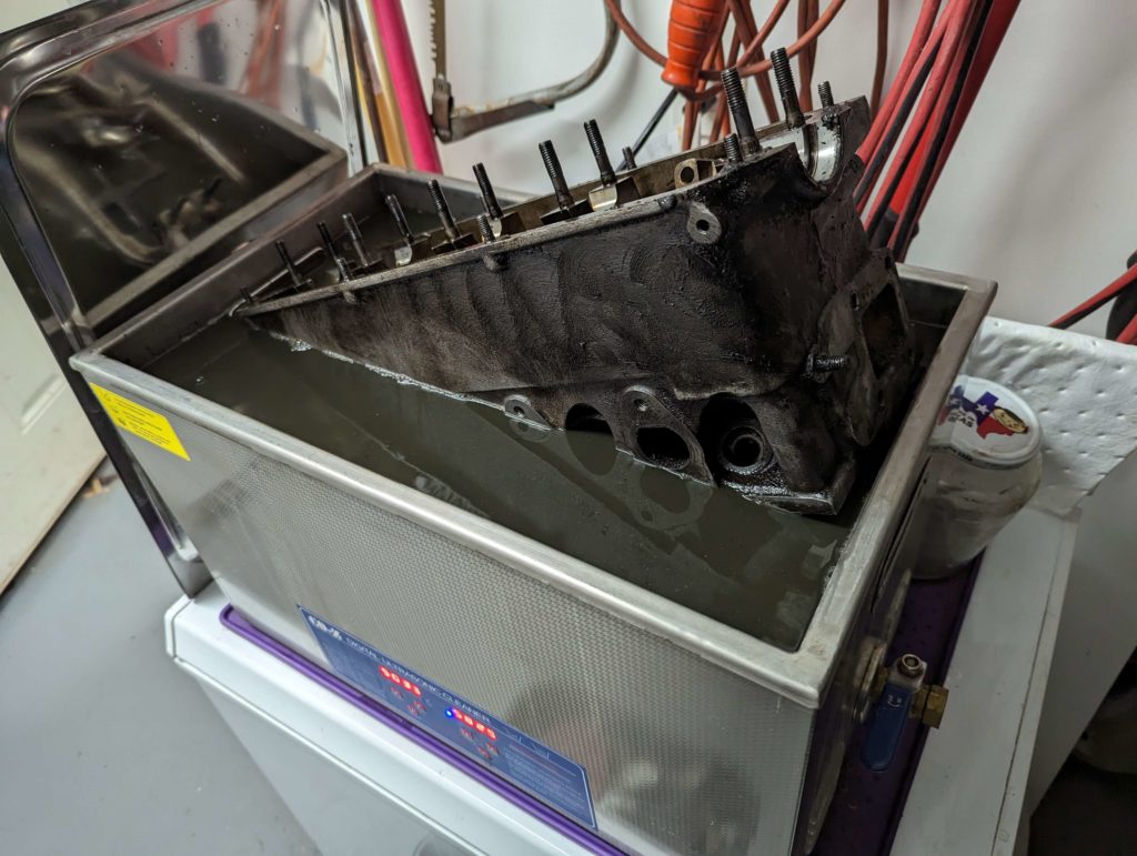
The engine went back together without much fuss. The Factory Service Manual the Jeep came with has this detailed out which made the reassembly smooth. The intake manifold was cleaned up in the ultrasonic cleaner.
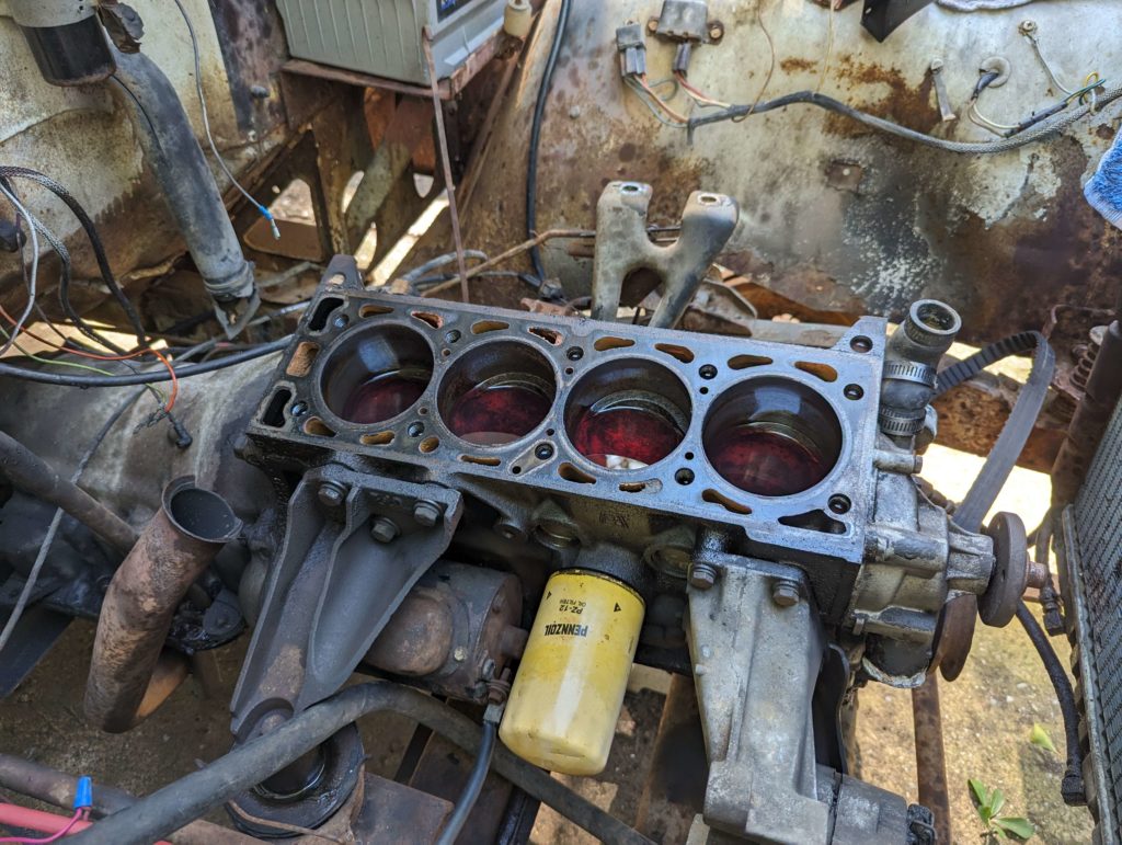
When the cylinder block was getting ultrasonic cleaned, I soaked the cylinders in ATF to make sure the rings where loose and unstuck completely.
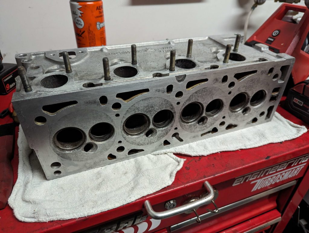
Then I cleaned up the deck of the block. In cylinder 3 I went after the rust that was deposited on the cylinder walls with scotchbrite. I managed to get most of the rust off. What is interesting about this block is the material. It is called Alusil which is an aluminum / silicon alloy. When they hone the cylinder walls they use a special polishing compound that can wear the aluminum but not the silicon. What is left is cylinder walls that are silicon which is very wear resistant. Should be able to remove the rust off the cylinder walls and leave the silicon walls…. or I wear through the silicon and the 3rd cylinder eats itself :)
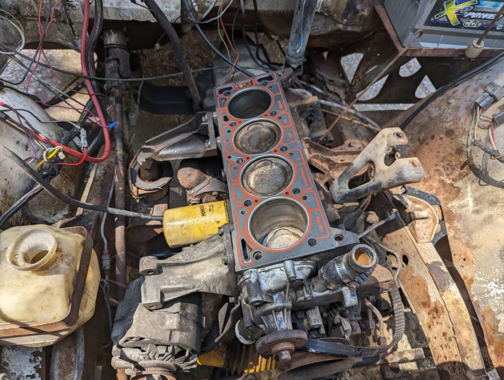
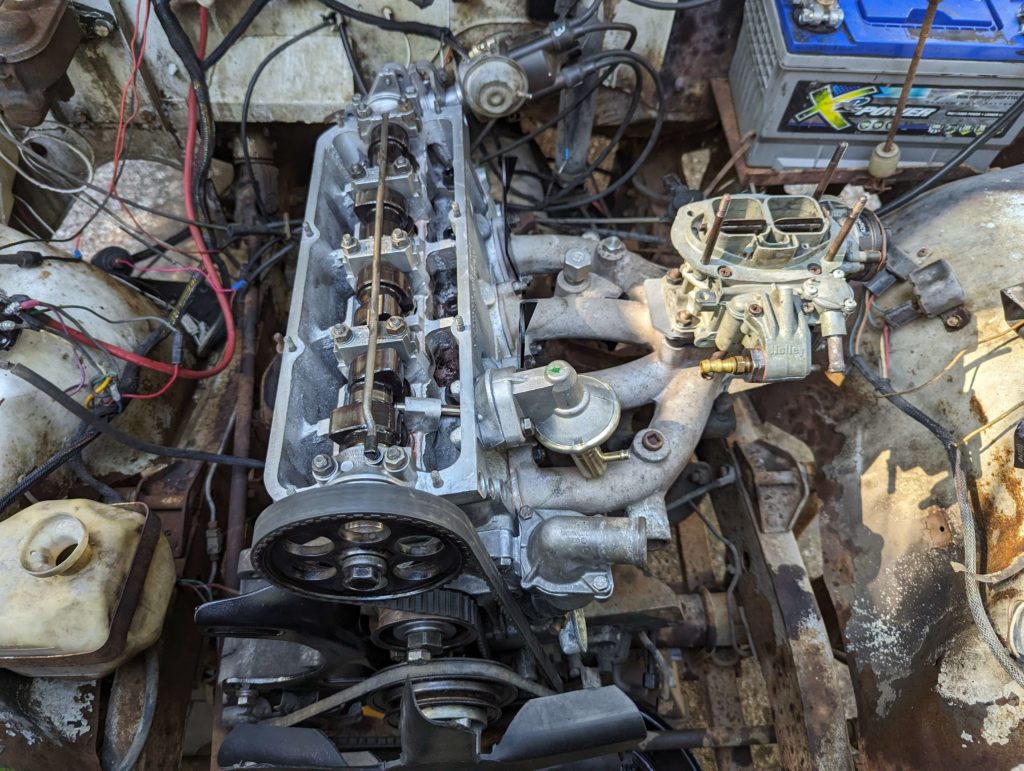
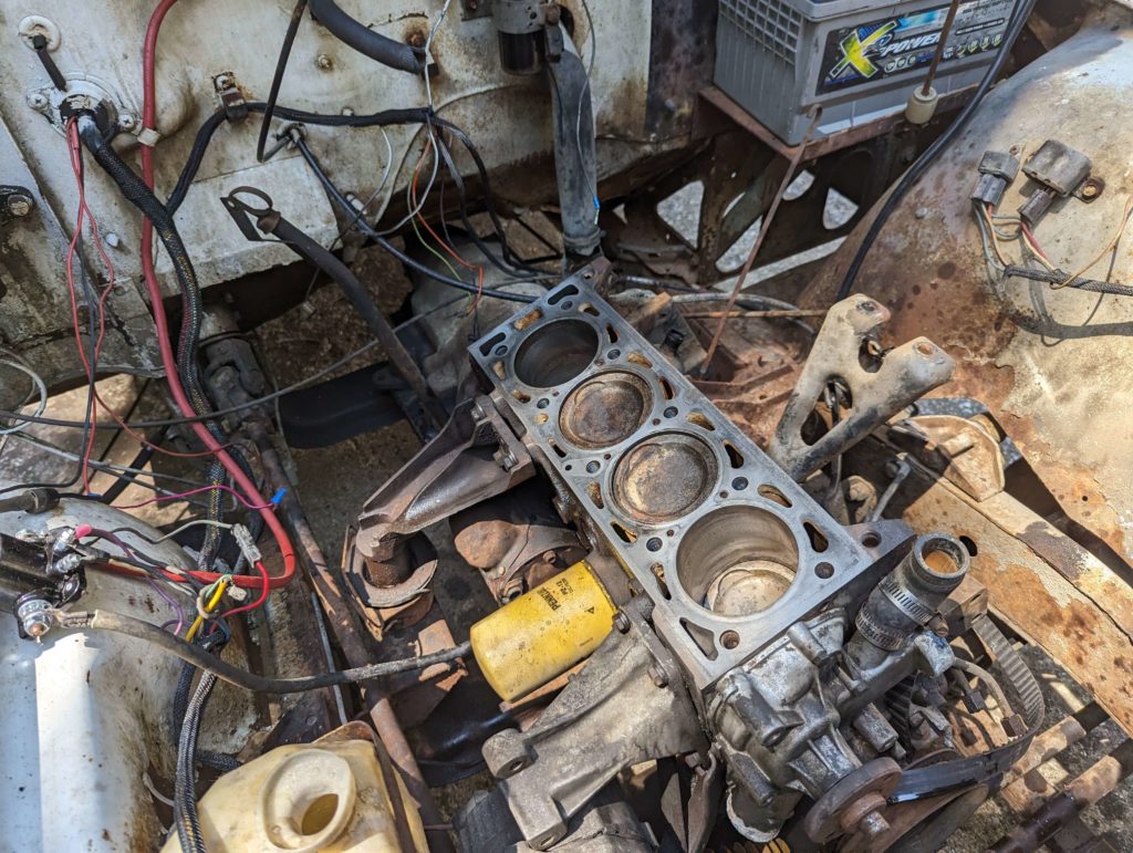
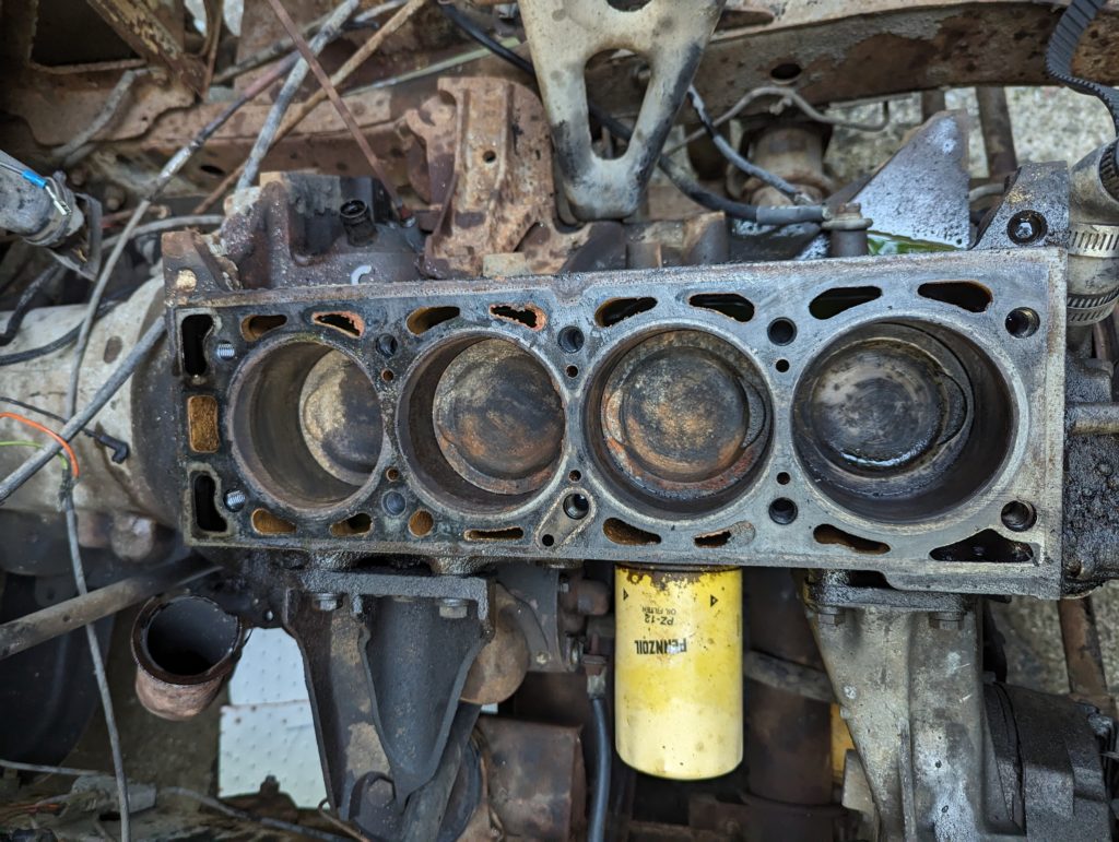
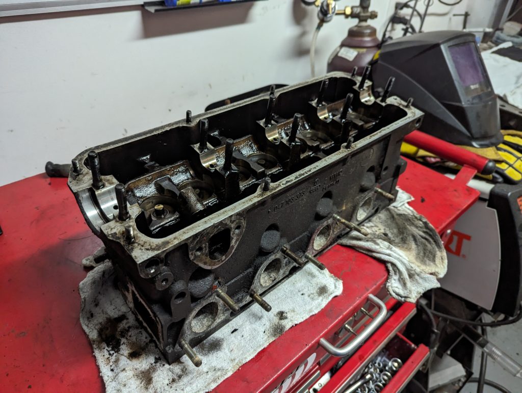
After seeing the fuel blow back through the carburetor, it is time to remove the cylinder head and see what is up with cylinder 3. I removed the valve cover, intake manifold, exhaust manifold, and various other external engine parts till I could remove the head.
Well not ideal but at least the pistons don’t have holes and no foreign objects in the cylinders.
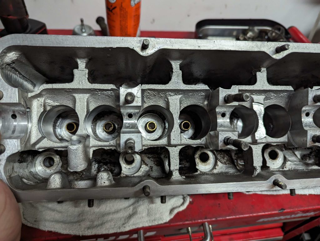
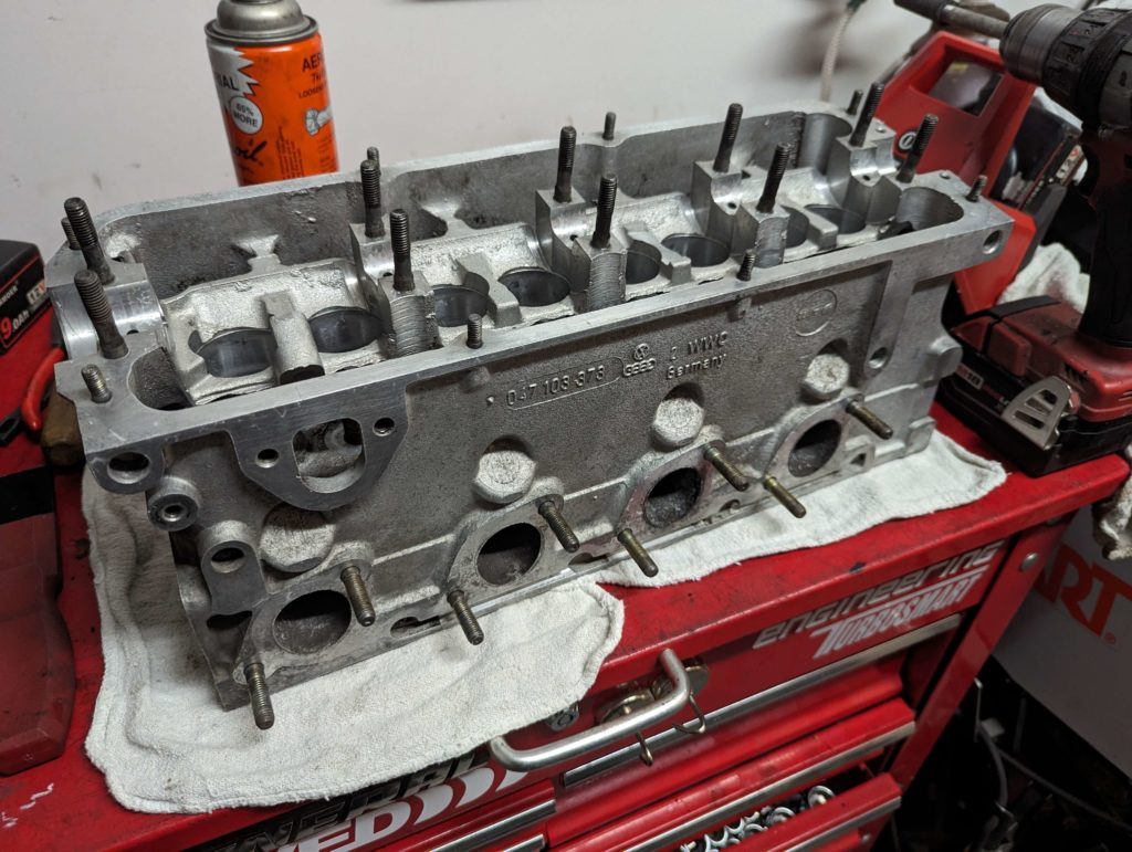
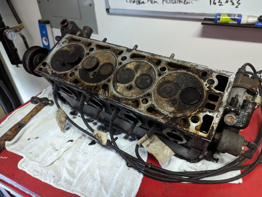
The cylinder head is coated in oil and corrosion.
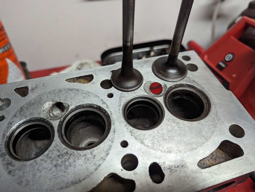
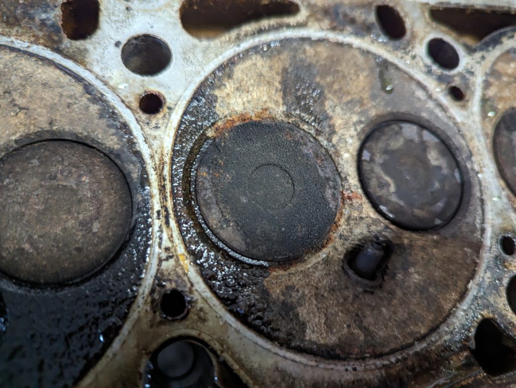
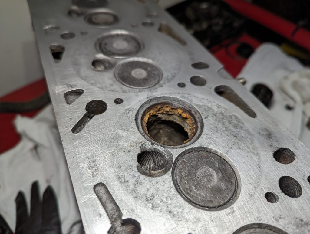
Here is a close up of the intake valve on cylinder 3. Seeing some crusty rust.
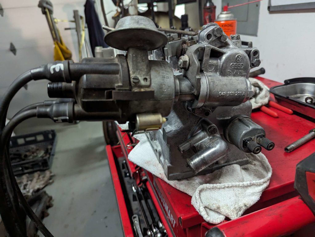
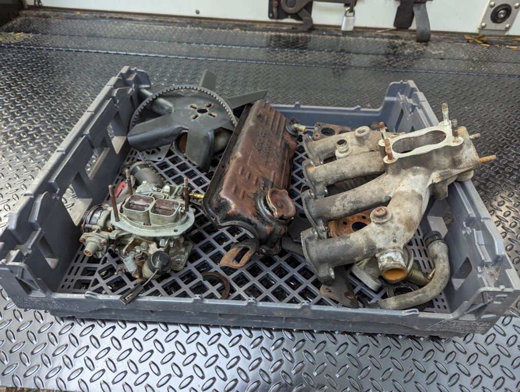
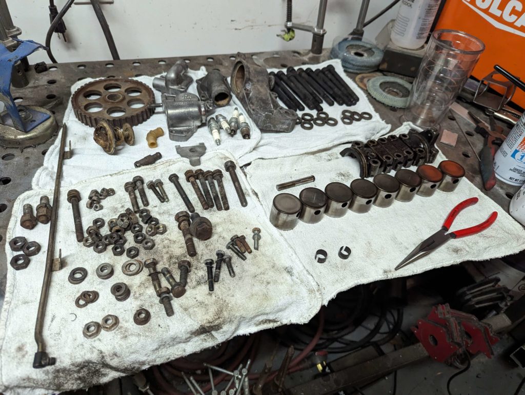
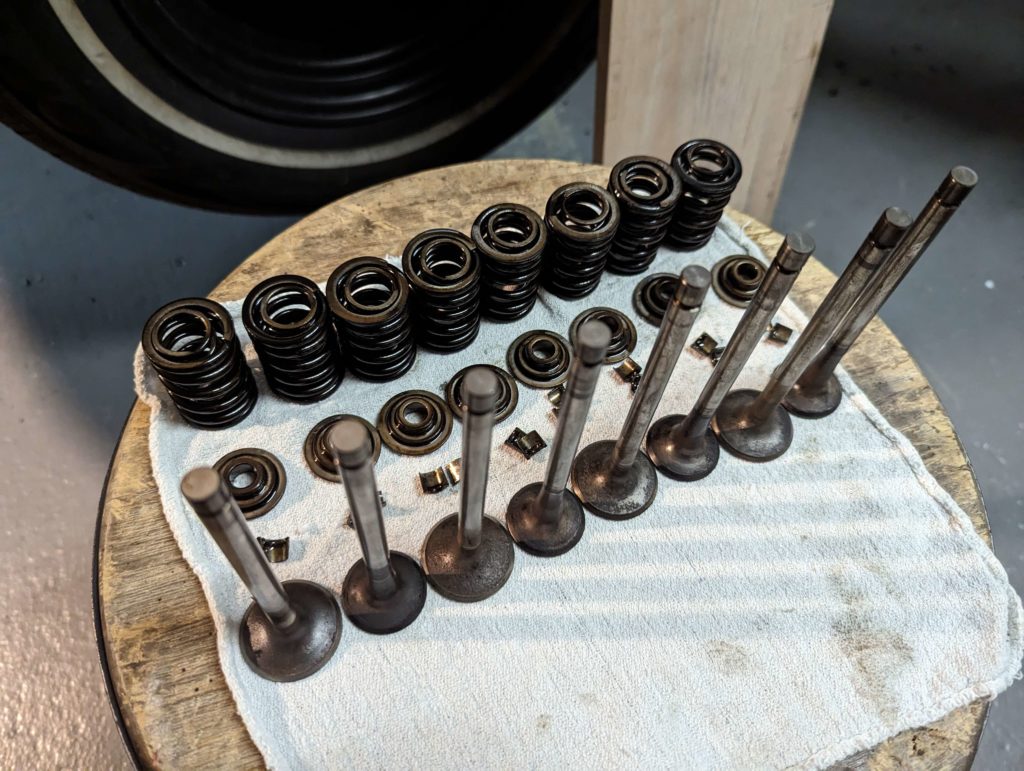
Rest of the parts for the engine. Going to ultrasonic clean all these (minus the carb I just rebuilt) before reassembly.
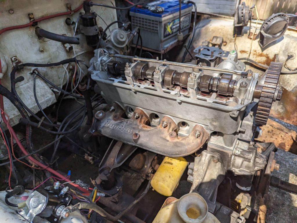
Tearing down the cylinder head more. So far everything looks ok. Cam, tappets, and surfaces look nice and not abused.
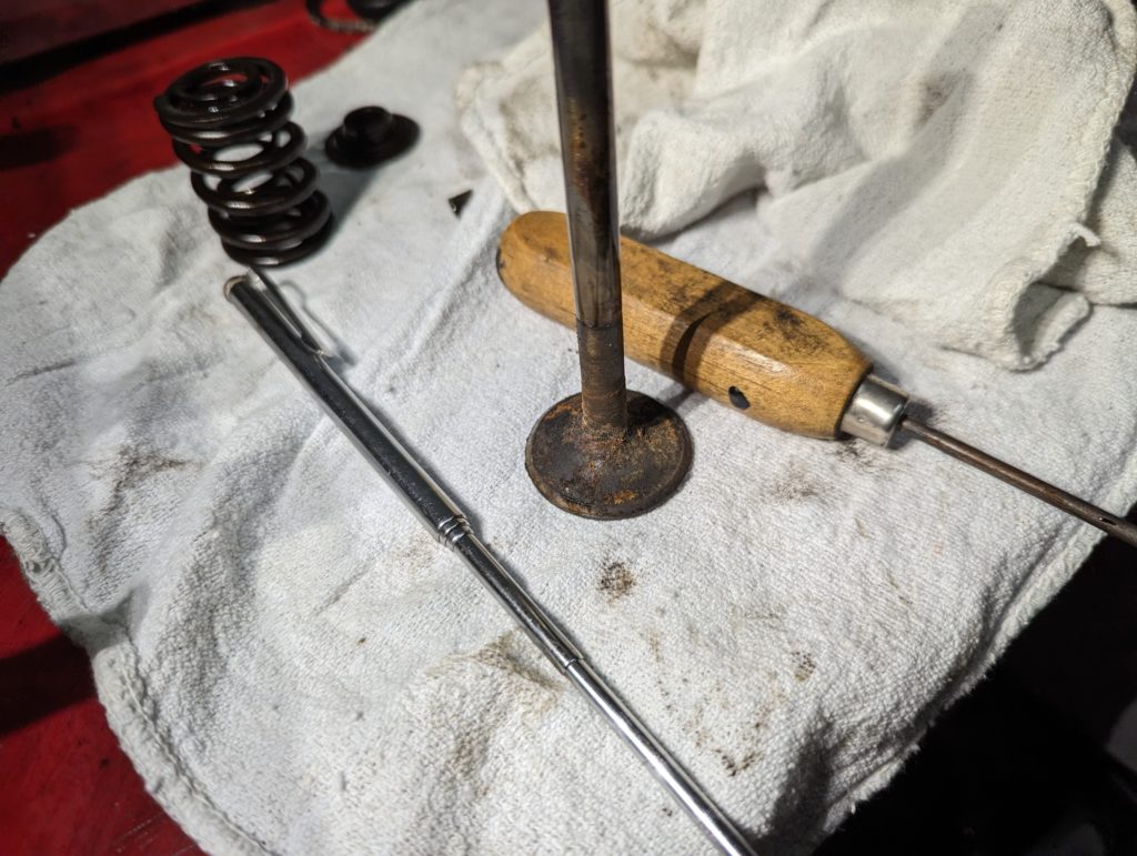
I cleaned up the surface of the head and removed the intake valve of cylinder 3 to make sure this is repairable.
The valve is stainless so this rust is just deposits, should clean up with a brass wire brush. The intake port is rough. I won’t know if the seat is salvageable till I get the surface rust off.
Here is the rest of the internal parts after cleaning through the ultrasonic cleaner and a brass wire brush on the valves to clean them up.
The cylinder head didn’t exactly fully fit in the ultrasonic cleaner but we will make this work.
Ok before we get into the carburetor rebuild I did manage to get the engine to run on 3 cylinders. I popped off the top of the carb so I could manually fill the gas bowls.
The engine does run but it is not happy at all. There is a back pressure through the carburetor. I suspect that cylinder 3’s intake valve is rusted up and not closing. This explains the zero compression as well. You can see the back pressure blowing gas upwards out of the carb and how much blowby the engine has. Oil is got everywhere!
The Jeep came with a 2 rebuild kits and a parts carburetor so getting at least one functioning carburetor should be doable!
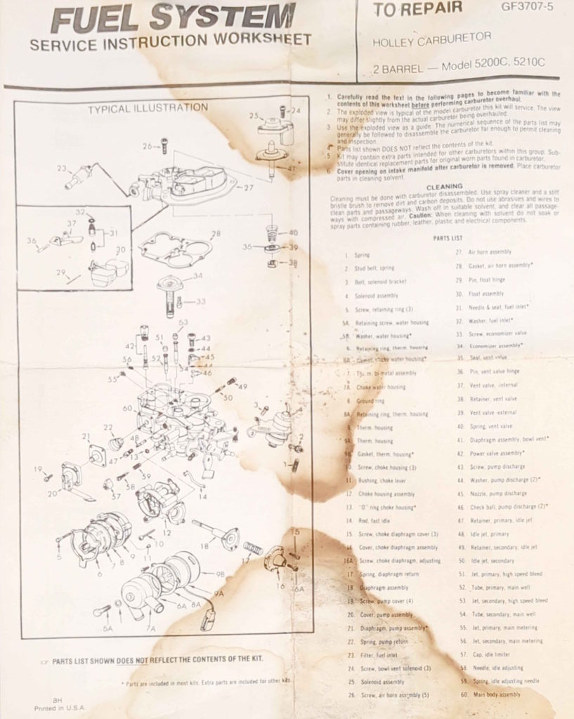
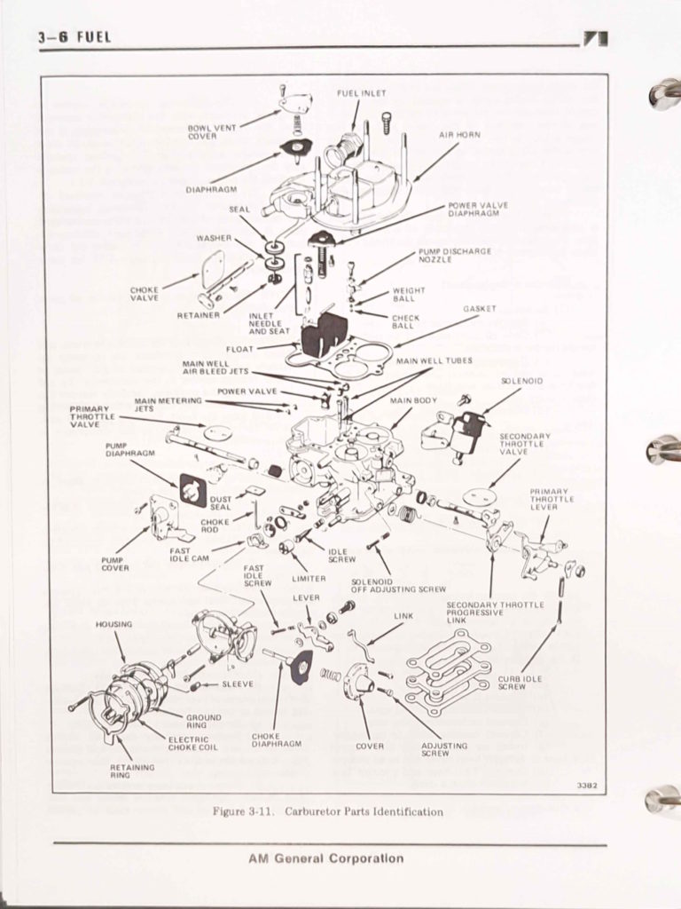
The carburetor is a Holly 5210 which is Holley’s version of the Weber 32/36. It even says Weber inside the bowl. This page has a good break down of how the carburetor comes apart and is reassembled.
Above is the diagrams from the carburetor rebuild kit and the diagram from the DJ-5G service manual.
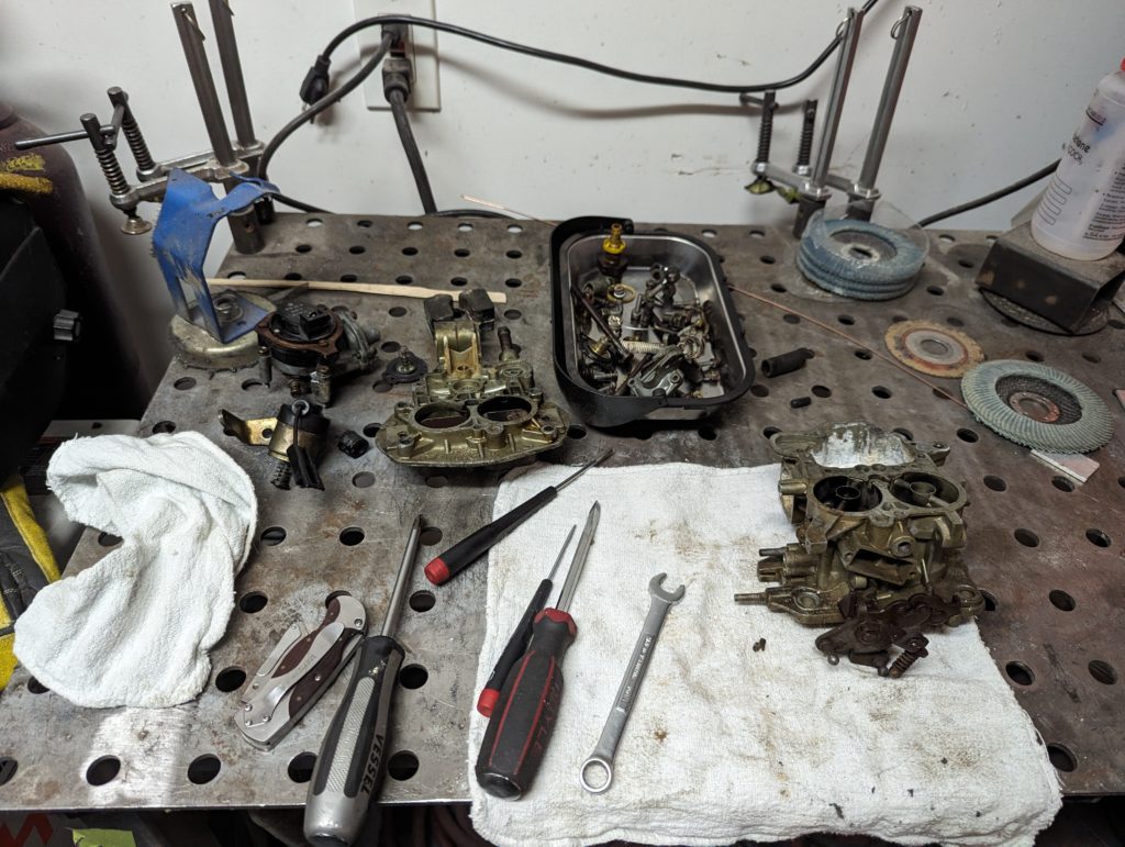
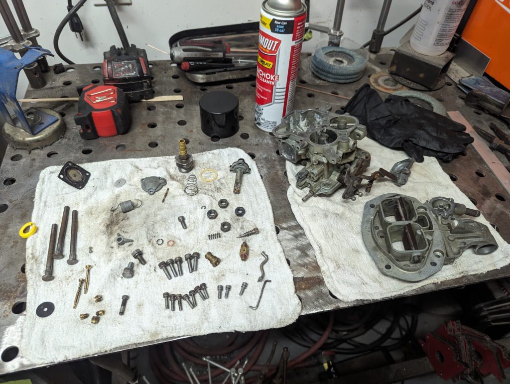
I disassembled the carburetor and organized the parts for it.
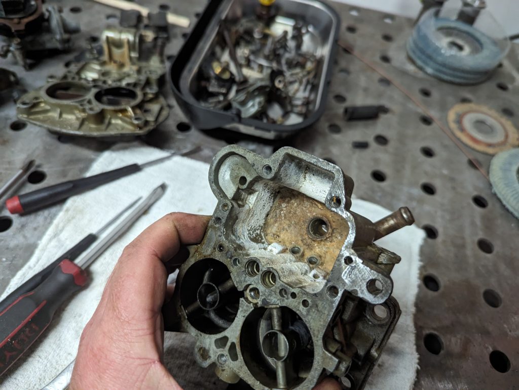
Ooo that fuel bowl is crusty. I put all the parts in my ultrasonic cleaner with a parts cleaner solution overnight.
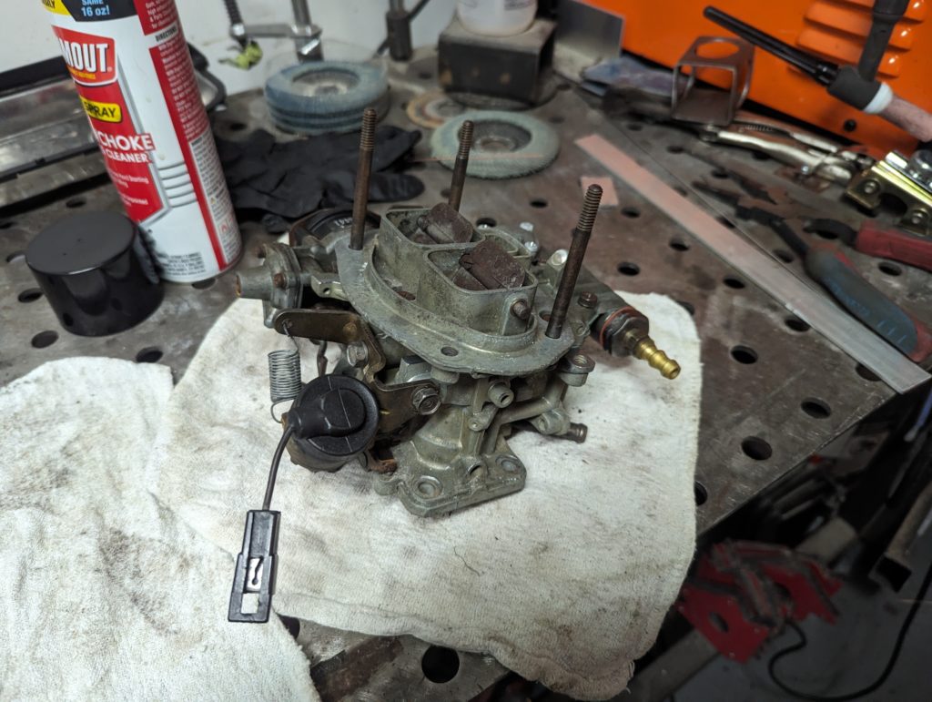
After some careful cleaning with some carb cleaner and scrubbing the stuff the ultrasonic cleaner didn’t remove we have a pretty clean carburetor. The jets I hit with a brass wire brush to really get the crust off.
All back together. I am missing one of the air cleaner studs so I will have to pick up a spare bolt from the hardware store.