Category Archives: Appnotes

Unboxing a DC2254A-A Evaluation board for the LTC2965-1

For keeping the time for the Cat Feeder Unreminder I am planning on using the LTC2956-1 which is a super low power timer that has push button reset control. It can accurately handle very long timers that a traditional RC style timers (think 555 timer) wouldn’t be able to do.

To see if this chip will work for my application I picked up the DC2254A-A evaluation board.

The box the DC2254A-A evaluation board comes in.

Inside the box.

The Evaluation Board

Here is the datasheet for the evaluation board.

For my use case, I am going to pull ONMAX to GND which will disable the timer that turns off the AWAKE timer. I will toggle the Sleep pin from low to high to low to reset the timer.

Seems to work!

Appnote: Parallax Propeller layout. Dual SMD footprint.

The Parallax Propeller MCU runs in 3 different flavors. A DIP-40 package (P8X32A-D40), a LQFP-44 package (P8X32A-Q44), and a QFN-44 package (P8X32A-M44). This appnote covers the two SMD packages; LQFP-44 and QFN-44.

The schematic is fairly simple as its just to show a typical layout of for the Propeller. The part number for the crystal is a 6MHz which will run the Propeller at 96MHz. It is a common HC-49/US package so the standard 5MHz type crystal can be used with this layout.

I made a special footprint that can use both the P8X32A-Q44 and P8X32A-M44. This way a part shortage on either package won’t hurt production. I made sure to leave plenty of room around the chip and supporting circuitry for easy fanout of the I/O. Just make sure to route away from the X0 and X1 crystal I/O to reduce EMF.

Files can be found on the GitHub repository and the footprint itself can be found in the my Eagle Library.

Appnote: Using mosfets to expand the WS2801 LED Driver

The WS2801 is an interesting chip. It is a constant current LED driver with 3 drivers that the current can be set individually. This lends the WS2801 to be useful when driving RGB LEDs. Each channel runs off an internal 8-bit PWM (total 24-bits) that is serially clocked in over a 2-wire (data and clock) scheme. This gives each channel 256 levels of brightness. The WS2801 can also be chained together with other WS2801 chips to reduce I/O usage. It can drive up to 30mA of current per channel from 3.3V to 5V which is a fair bit of power.

What if more power and current are needed though? Page 9 and 10 of the datasheet shows that a NPN transistor like a 2n2904 can be used to increase the current sinking capacity. This is all good unless you need even more power. N-type mosfets can be gated to the outputs of the WS2801 in a similar fashion.

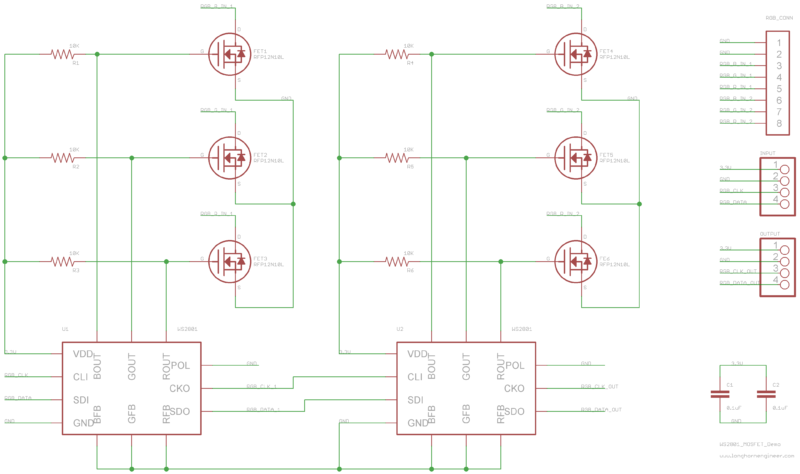
Above is an example schematic on how to connect the mosfets to a pair of WS2801 chips. The polarity pin (POL pin3) is pulled down to put the WS2801 into driving mode. The feedback pins (XFB pin4,5,6) are pulled to ground putting the driver in constant voltage driving mode. Pull up resistors are needed on the mosfet gates as the outputs of the WS2801 are open-drain gates.

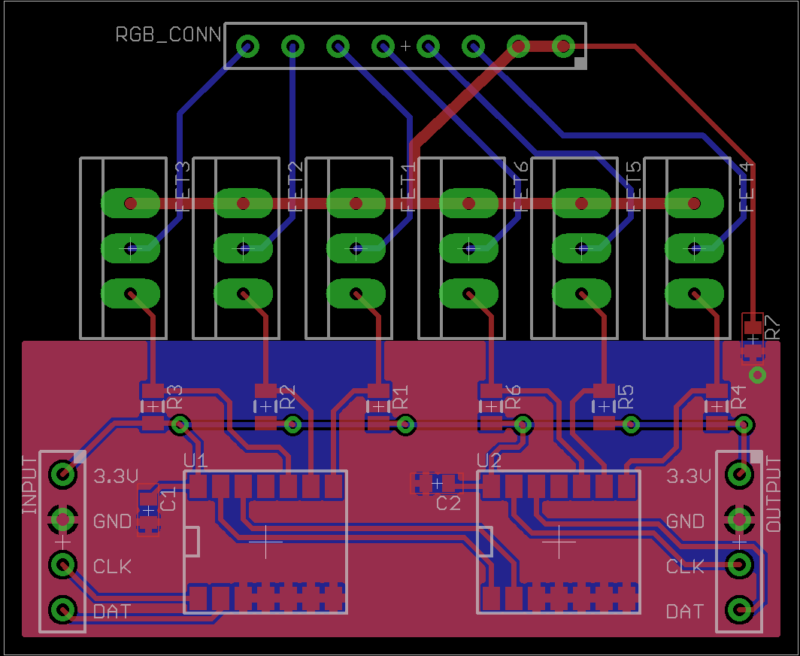
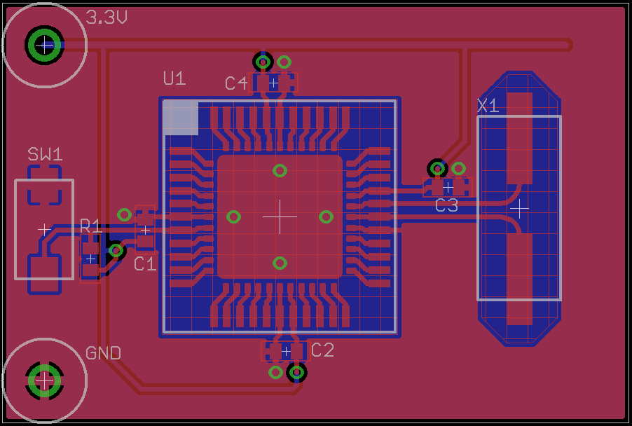
Demo layout of the dual WS2801 schematic. The WS2801 chip is a really nice chip to layout as the pinout is well thought out. Because two power sources are used (3.3V and voltage for the LEDs) the grounds must be connected to give the same reference voltage. A zero ohm resistor at R7 is used to connect these two grounds. A ferrite bead could be used here as well to reduce noise crossover if the high voltage LED power source is noisy.

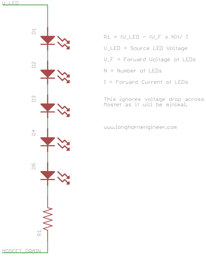
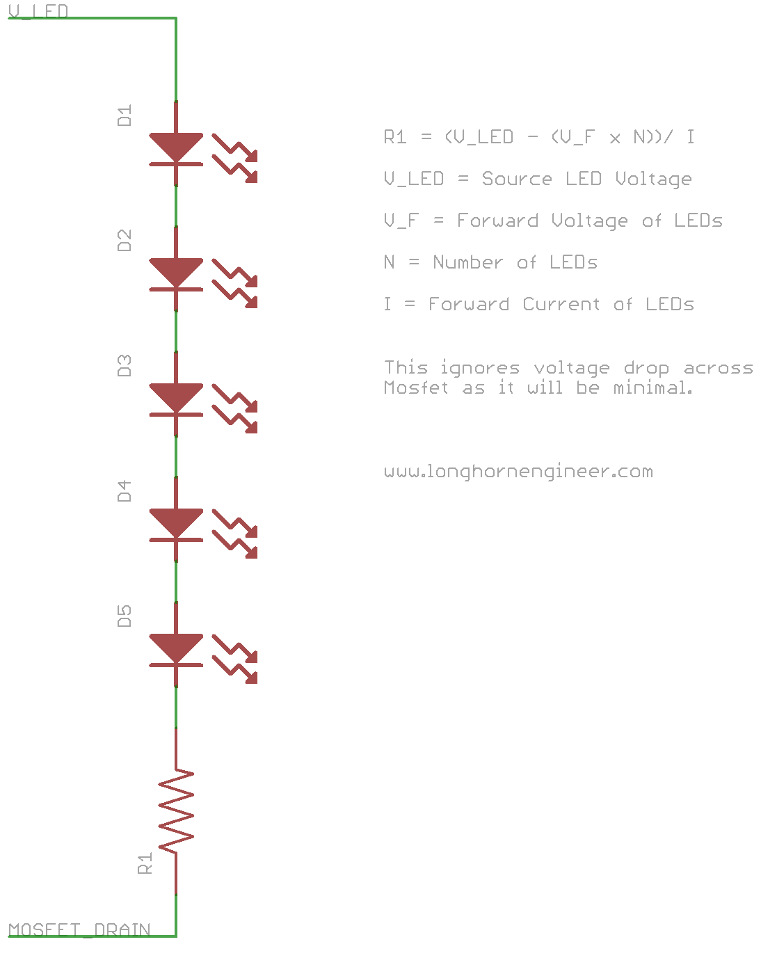
The high power LEDs should be connected to the mosfet drain through a current limiting resistor. Multiple LEDs can be connected together serially if the supply voltage is high enough. The voltage drop across the mosfets can be generally ignored as the resistance is usually around .2ohms for low resistance series (RSon) mosfets.

R1 = (V_LED - (V_F x N))/ I


Where
R1 = Resistor value
V_LED = High voltage LED source
V_F = Forward voltage of the LEDs
N = Number of LEDs
I = Forward current of LEDs

Also you have to make sure your resistors are large enough to handle the current load.

RW = (V_LED - (V_F x N)) x I


Where
RW = Resistor watt rating
V_LED = High voltage LED source
V_F = Forward voltage of the LEDs
N = Number of LEDs
I = Forward current of LEDs

For example the OVSPRGBCR4 RGB LED will be used. The source voltage will be 24V and 7 LEDs will be chained together. The forward current (If) of all 3 channels is 250mA. The forward voltage (Vf) of the red channel is 2.3V and the Vf of the green and blue channel is 3.4V.

RED:
(24V - (2.3V x 7))/ .25A = 31.6ohms
(24V - (2.3V x 7)) x .25A = 1.975W


GREEN & BLUE:
(24V - (3.4V x 7))/ .25 = .8ohms
(24V - (3.4V x 7)) x .25A = .05W

Finding a resister to work with the Green and Blue channels of the LED is fairly easy but the Red channel is a bit difficult due to the high power rating needed. A quick look on mouser yields limited selection of 32ohm resistors in a big enough size to handle 2W but two 16ohm 1W resistors in series would work just as well and are much easier to find.

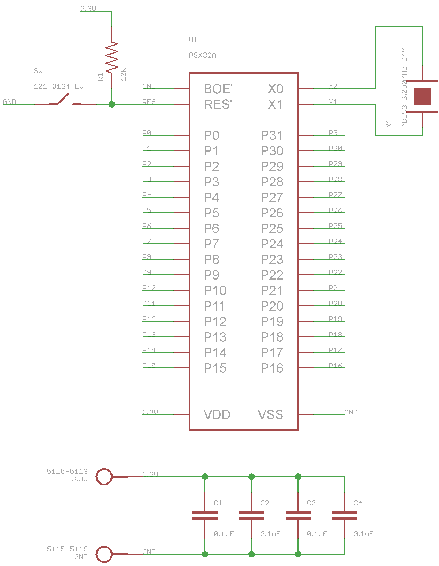
I am using this method to drive banks of RGB LEDs on the PinHeck Pinball System for general cabinet illumination. The Eagle files of the schematics and board layout are on GitHub. I also have some demo SPIN code for the Parallax Propeller chip to drive the WS2801 that I wrote awhile back.

MSP-430 LaunchPad UART and FIFO

This code is currently for the MSP430G2553 on the Ti LaunchPad. The MSP430G2553 has a built in USCI that can be used for UART. Unlike lower end models of the value line you do not have to make a slow software UART. I looked online and did not see any UART libraries that where nice to work with without hacking them apart. I did not see any FIFO implementations at all either. They generally waited on the UART to finish its business before sending more data.

The advantage of the FIFO allows the MSP430 to push that data into the FIFO as fast as it can and let the hardware UART do the rest of the job. This frees up the CPU to do allot more stuff. The only bad thing is that if the FIFO gets full you start loosing data. The code has a global flag to let the main code know that the FIFOs are full.

The Receive (RX) portions of the code also have a global mailbox flag to notify the rest of the code that the UART received something. This would be useful if you need to send commands to a robot or device.

There are 4 different flavors of the code.

1. RX TX
2. RX TX with a FIFO
3. TX only
4. TX only with a FIFO

The code without the FIFOs waits on the UART during the transmission but uses far less memory then the FIFO code. You have to sacrifice speed or memory on this one. The TX only code strips out the RX portions if you just want to have the msp-430 print to a terminal. This is useful for debugging purposes.

If you are going to use this on the MSP-430 LaunchPad then you will need to cross the RX and TX lines. This pdf I found on the internet explains on page 3 (step 6) what I am talking about.

RX TX UART Code (CCS V5)
Project File
main.c
uart.c
uart.h

RX TX UART FIFO Code (CCS V5)
Project File
main.c
uart_fifo.c
uart_fifo.h

TX UART Code (CCS V5)
Project File
main.c
uart_tx.c
uart_tx.h

TX UART FIFO Code (CCS V5)
Project File
main.c
uart_fifo_tx.c
uart_fifo_tx.h

FIFO Code (CCS V5)
Project File
fifo_.c
fifo.h

WS2801 – 3 Channel PWM

The WS2801 is a 3-channel constant current LED drivers that is designed for controlling chains of RGB LEDs. The IC is controlled by a 2-wire serial control scheme that allows multiple WS2801 to be chained together. You can find the WS2801 in the link below. This demo code basically shifts out 24 bits (8bits per color) using a 2-wire protocol. This code only works for one WS2801. There is a object designed for multiple WS2801 already in the propeller OBEX. That design uses too many resources for use on my pinball machine so I wrote this to use as little resources as possible (no new cog).

The idea would be to have the WS2801 PWM a set of mosfets which would in turn be connected to the string of LEDs. This way you could light up a bunch of RGB LEDs without allot of CPU time taken from the Propeller. The Propeller only has to mess with the WS2801 when it needs to change the PWM signals.

Where to buy the WS2801.
Demo Driver

http://www.youtube.com/watch?v=EugcTOxVHx8