
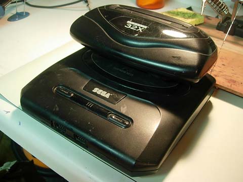
How to make a Sega Neptune
Read through the instructions carefully before attempting to start this project. Also read the disclaimer.
This guide is sponsored by Super Fighter Team.
The first Neptune I built can be found here. Since then I have updated the design to require only one power supply. The Genesis 2 and 32X module can run off of 650mA which is under the 850mA that the stock power supply offers. You may wonder why Sega didn’t just have the 32X draw power from the cart slot or just have a jumper cable running from the back of the Genesis power supply to the 32x? Well the cart slot can’t power the amp hungry 32x but I don’t know why Sega went with a separate power supply over a just a splitter/jumper.
This guide is a step by step overview of how to make a Sega Neptune that only uses one power supply and features region mods. This project may look daunting but it is fairly simple and straight forward. There are no supper tricky soldering situations (unless you do the region mods) so anyone that has moderate experience with a soldering and desoldering iron can build a Neptune.
For this project you will need the following tools
- Soldering Iron – 15W-25W
- Desoldering Iron – 25W
- Needle Files
- Assorted Screwdrivers
- Dremel like tool with Cutting Discs
- Needle Nose Pliers
- Hot Glue Gun
Parts Needed
- Sega Genesis 2
- Sega 32X
- Lots of Ribbon Cable
- 3 DPST Switches (for region mods)
First start by disassembling the 32X. There are a lot of screws so make sure to get them all. Some are hidden on the vertical part of the 32X so make sure to get those too.
After taking the top off the 32X remove all the screws holding the RF shielding and 32X board to the casing.
With all the screws gone the vertical portion of the 32X should slid through the bottom casing. The sides of the vertical portion should then be removed.
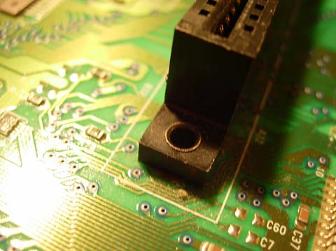
Flip the 32X over and find these tabs near the underside of the cart slot. Straighten them out with pliers and flip the 32X back over.
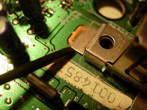
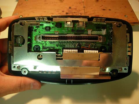
Take a small flat head screw driver and pry the RF shielding off the 32X cart slot. Make sure to be careful and not slip as damage to components and traces can occur.
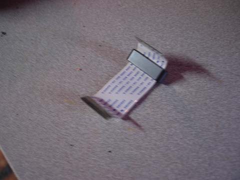
There are two white ribbon cables that connect the two 32X boards together. Take these ribbon cables off by pulling them straight out of the slots that hold them in place.
Using a hammer, smash the ring to remove it. This ring is used to help prevent data corruption over the ribbon cable and please the FCC but the 32X seems to work fine without it and the 32X needs the space to fit inside the Genesis 2 case. After removing the ring replace the ribbon cables back into the slots on the 32X.
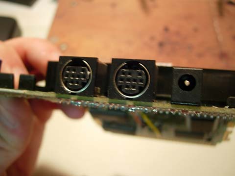
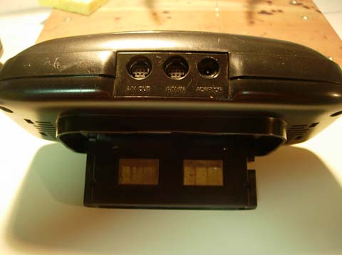
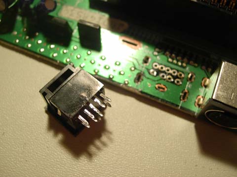
Using a desoldering iron remove the video output from the 32X. Don’t force it as you will have to use this part again. When removed take the metal shielding around it off.
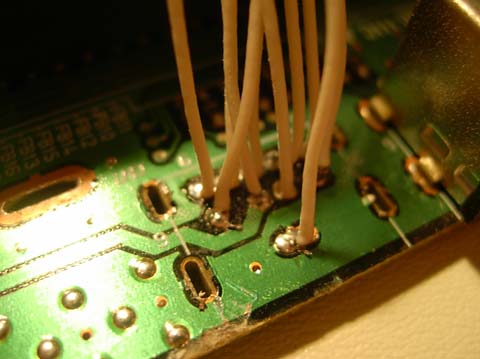
Solder some wire about 6 inches long to the video output contacts. I used standard ribbon cable wires for it.
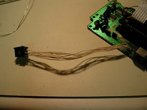
Then take those wires and solder them to their corresponding points on the jack. Its a good idea to test the 32X now. If it fails to work make sure you haven’t bridged a connection anywhere.
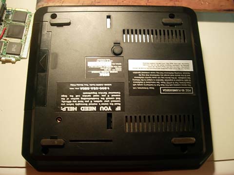
Now to disassemble the Genesis by removing the 4 screws that hold the Genesis 2 case together and take the top off.
Take the cart flaps off the underside of the top of the case by removing the 3 screws that hold it in place.
Now remove all the screws that hold the Genesis board to the RF shielding and case.
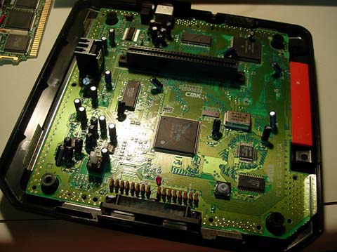
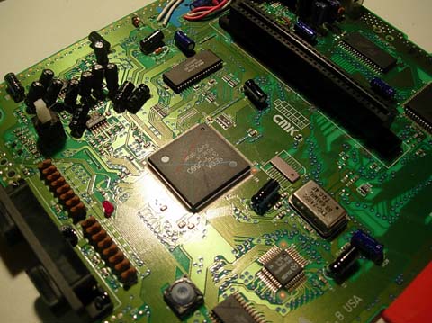
Some boards have different layouts. This one has the 7805 voltage regulator and filter capacitor right next to the cart slot so it will have to be relocated to the back of the case. If the board has the 7805 located at the back of the board skip the relocation of the 7805 and large capacitor.
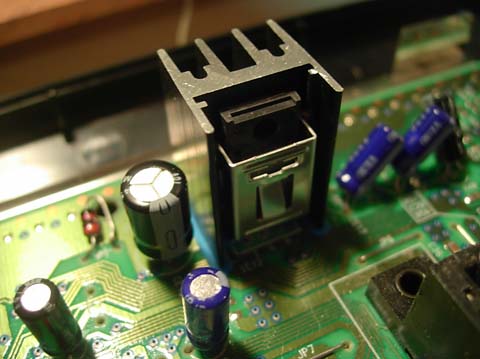
Flip the board over to the bottom and desolder the 7805 and capacitor. Pay attention to how both where orientated on the board.
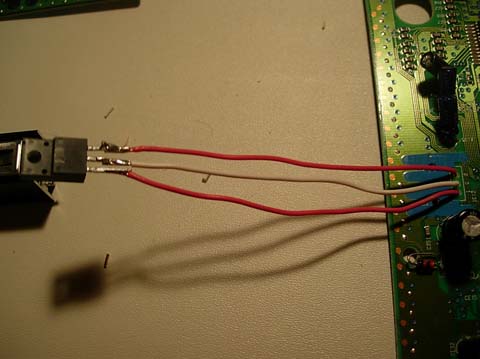
Reattach the 7805 by soldering 3 wires of about 4 inches in length to the 7805 and the board. Make sure to get the orientation of the 7805 correct. Use a heavier gauge like 20 AWG for this.
And do the same for the large cap.
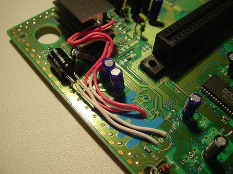
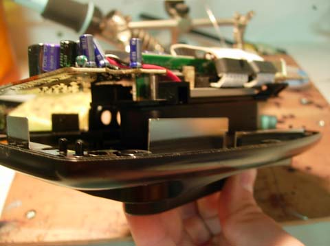
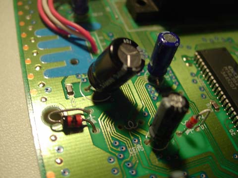
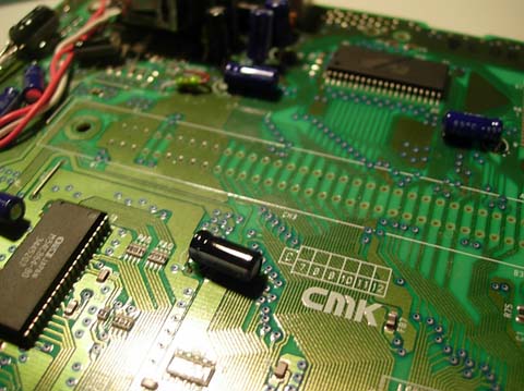
Now flatten the capacitors on the board to reduce the overall height off the board. Just heat up the contacts and pull them slightly to extend the leads a bit then fold the capacitor over. Be careful not to pull the traces off the board or rip a leg off a capacitor.
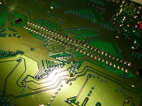
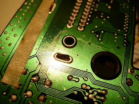
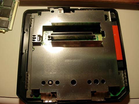
Now for the tricky part. Desolder the 64 contacts to remove the cart slot on the Genesis board. However, the cart slot won’t come off the board without removing some rivets.
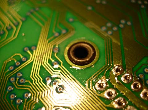
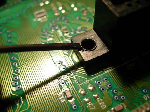
To remove the rivets take a small flat head and position it like shown above. Push the edge inward. Be careful not to slip.
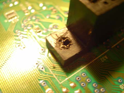
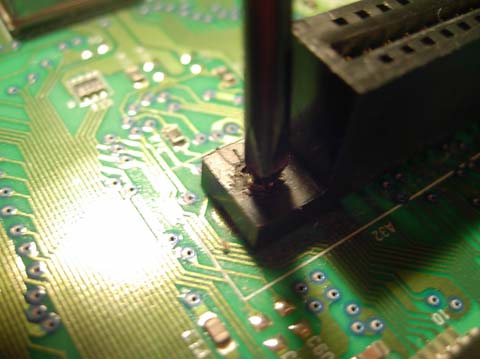
Then take a Philips head screwdriver and push the rivet out of the board. The cart slot should come free from the board now.
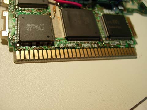
Clean the contacts on the 32X by rubbing some fine steal wool on them. This removes the oxidized layer on the metal and makes soldering easier.
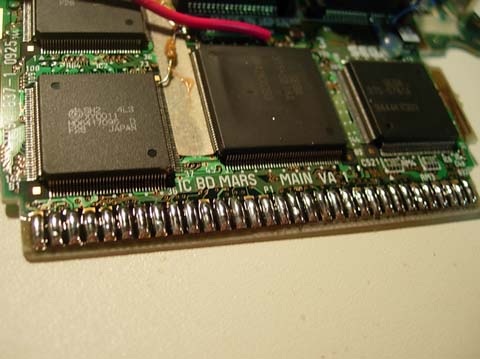
Tin the contacts on the 32X. Make sure to use plenty of flux.

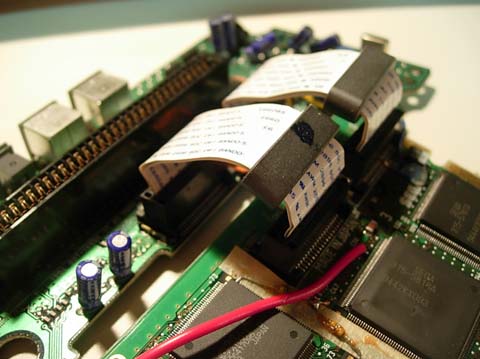
Using ribbon cable attach the 32X to the Genesis. The wires closest to the front of the Genesis need to be cut at 4″ and the other row needs to be 3.5″ in length. This will ensure that the wires are straight and untangled.
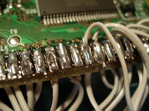
On the far side of the 32X the wires need to be attached upside down. When the 32X is folded down on top of the Genesis these wires will lie straight. I should have taken more pictures of this part but my first Neptune I built has some pretty good pictures of this part Neptune. I used thicker wires in that version but the method is the same.
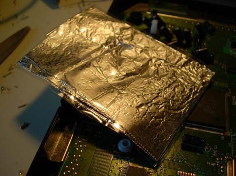
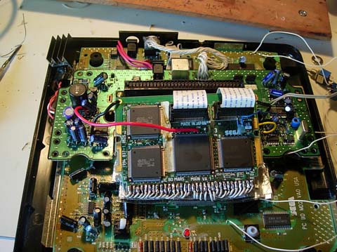
Make 3 aluminum shields. I think I made them 3.75″ by 4″. They are 4 layers thick and covered in packaging tape to prevent short circuits. These help separate the two sets of wires and help prevent cross talk.
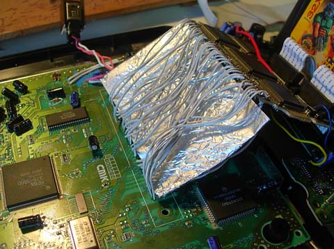
Place one in between the two sets of wires and one on each side of the wires like a sandwich. This is a good time to see if the Neptune is working. If it fails double check every connection and inspect the board for solder spills.
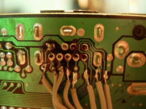
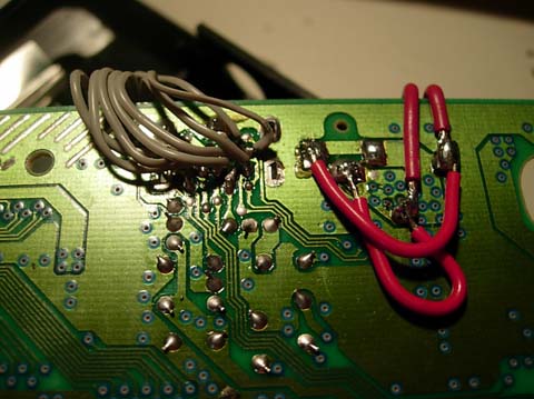
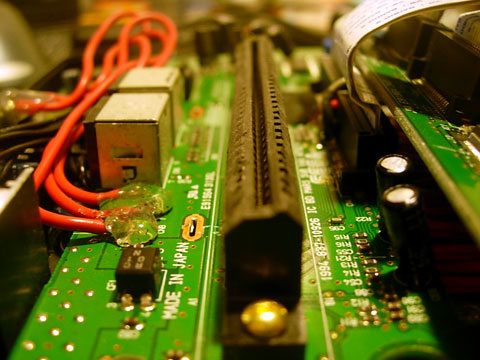
Solder some wires to the contacts shown. I cut my wires to be 7 inches long. This is to replace the cable that connects the Genesis A/V out to the 32X A/V in. Attach some heavy duty wire (18AWG) from the power input on the 32X.
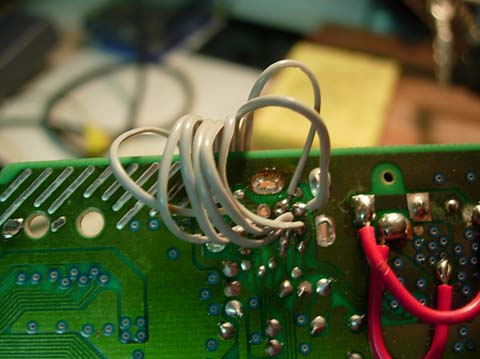
Now desolder and remove the video output on the Genesis board. Then attach the wires from the 32X to the exact same spots on the Genesis video output. Make sure to solder to the bottom of the board and leave the top clean. Then attach the power wires from the 32X to the input on the Genesis.
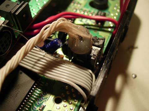
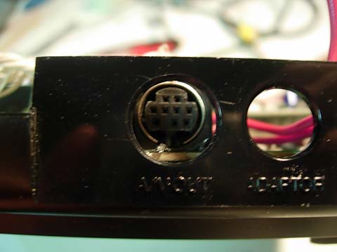
Now take the Video output from the 32X and hot glue it upside down to the old spot of the Genesis video output. The port may be a little high so file down the hole to make it bigger.
Double check every connection and test the Neptune. Remember to inspect the board carefully for solder spills. If it doesn’t work the problem most likely lies with your 32X/Genesis cart connection. Check to make sure the wires are straight and untangled.
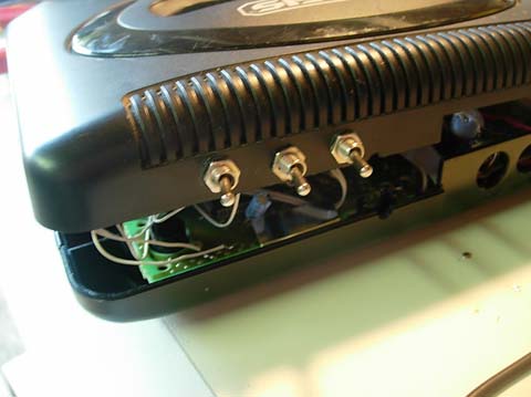
If region mods are wanted this is the time to do them. The mods are everywhere on the net so I won’t post on how to do them. MMMonkey has a really good guide on MD2 mods and for the 32X head on over to here. The 32X one is in french but google translates it pretty well. I used the simple version. I attached the switches to the back of the Genesis casing.
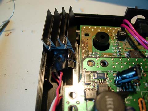
Bend the 7805 so it lies on in this corner. You may have to bend the bottom RF shielding to get it to fit.
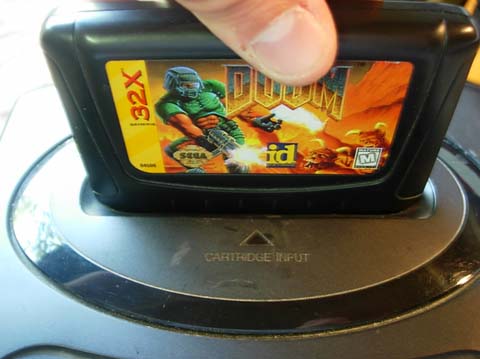
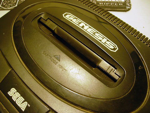
Genesis games are smaller then 32X games the cart slot needs to be widened. Place a 32X cart on top of the slot and trace around it with a pencil. File down the plastic till it fits.
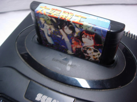
If you have an import JPN game you will have to cut some more of the cart slot. Use the same method.
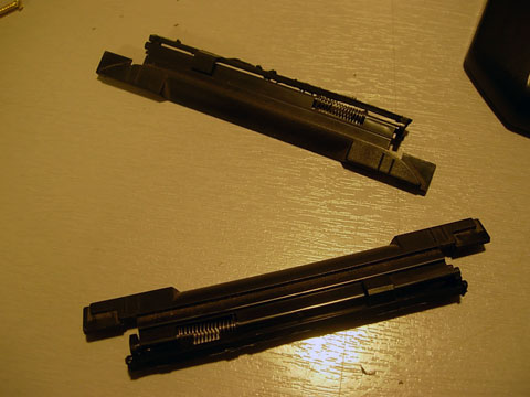
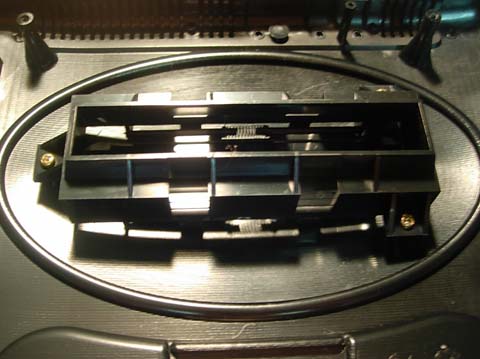
If cart slot flaps are wanted take the cart slot mechanism from the 32X an cut it down like shown above.
Hot glue these flaps to the inside of the Genesis 2 case.
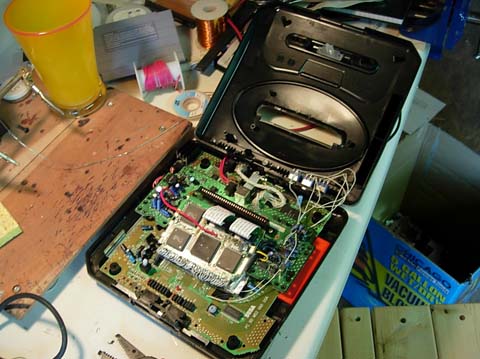
Use #4 1″ wood screws to attach the 32X to the genesis board and casing. The holes around the 32X cart slot will line up with the holes on the Genesis board. Go ahead and test the Neptune to make sure it works.
Place the cover back on the Neptune and test the cart flaps if you have them installed. Most likely the flaps will hit the cart slot. If so cut off the edges of the cart slot with your dremel.
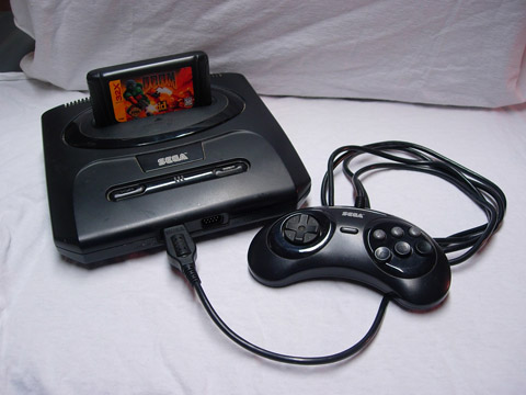
Put the cover back on the Neptune and replace the 4 screws. It is now done.
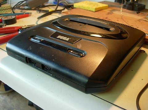
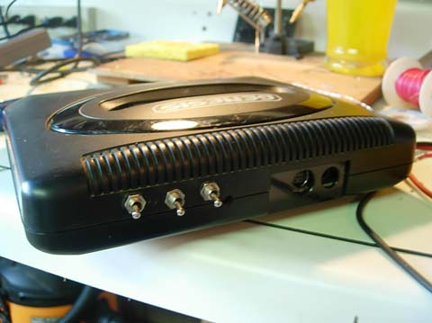
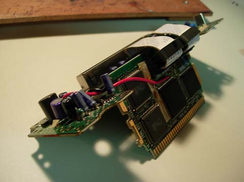
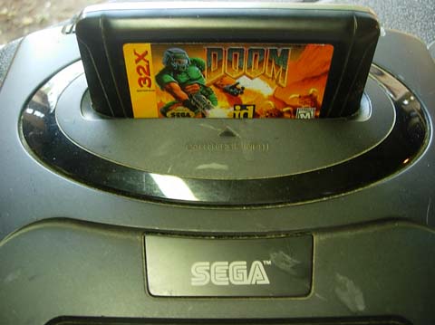
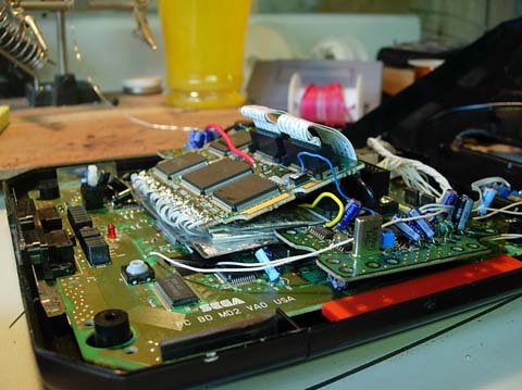
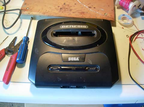
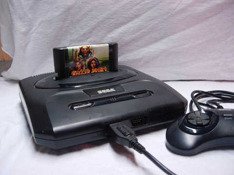
Some final pictures.
A special thanks goes out to Super Fighter Team for sponsoring this how to!