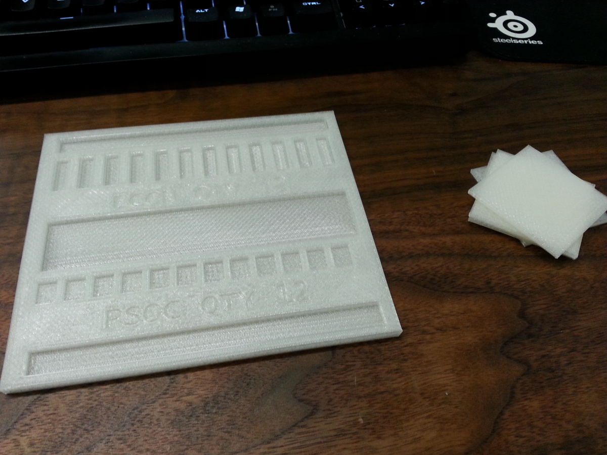
I had a couple spare PSOCs to test the part tray with and train the pick and place. The PSOCs fit very well with little wiggle. Will be training the machine on the placement of the parts on Friday.
https://www.youtube.com/watch?v=IaX2OAxJu0M
Here is a short little video of the pick and place positioning the FCC connectors onto the PCB panel. I am using double sided stick tape to replicate the holding force of solder paste. The pick and place is running at 10% speed to prevent the connector from sliding off the nozzle.
https://www.youtube.com/watch?v=g7EMVEv4fGs
This is the screen printer we are currently using at MacroFab. It is an old semi-automatic printer but it works well for its age. It has a vacuum table to hold down the pcb and suck the screen to the pcb. Put some coated stainless blades on it for smooth paste squeegee action.
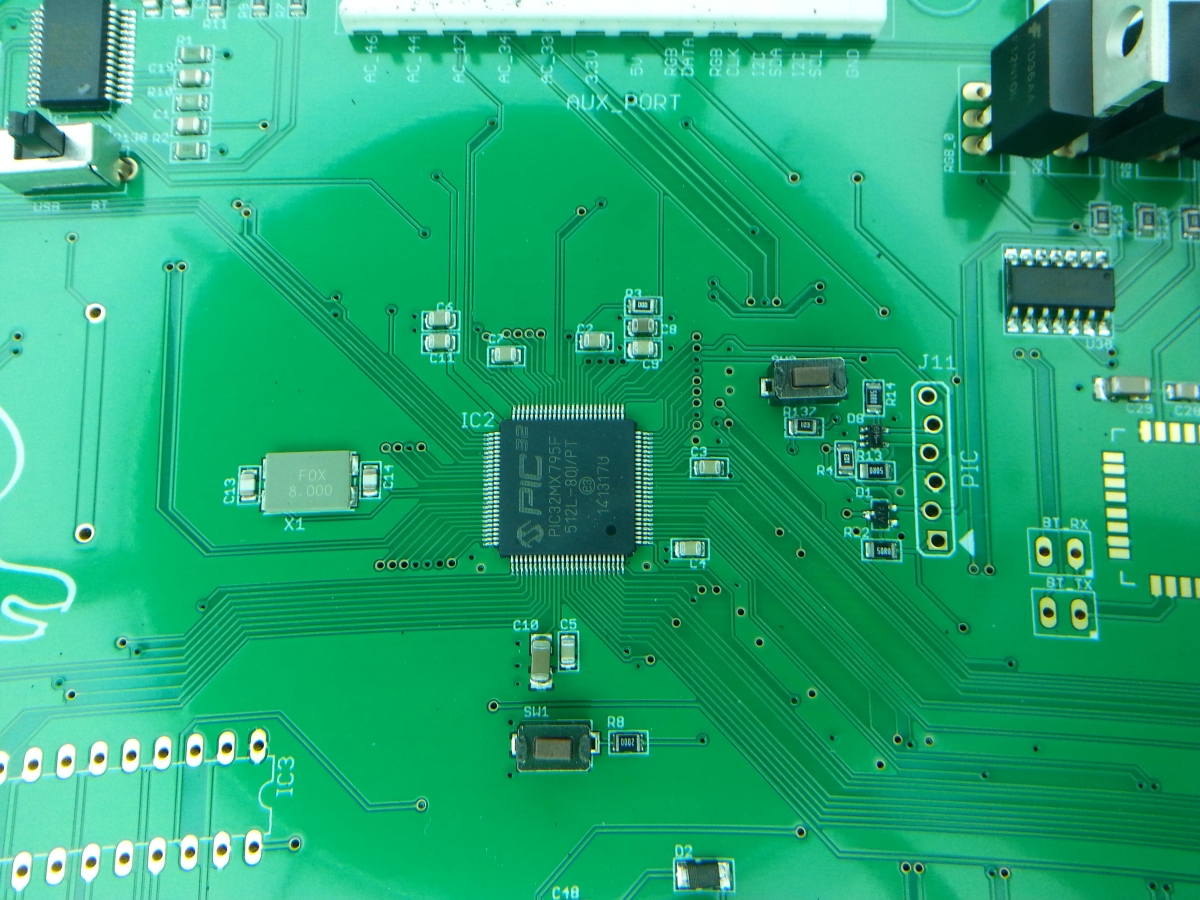
PIC-32 in TQ-100 package
The Pic-32 on the Pinheck Pinball System is a TQ-100 package which is .4mm pitch. We used a solder stencil and placed the part via the pick and place. Stencil was .1mm in thickness. Ran 25 boards and had no solder bridges.
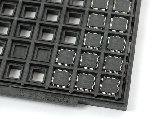
At MacroFab, I have been working with a DP2006-2 Madell pick and place for the past 6 months doing low scale pcb manufacturing while we test our software on it. Some parts (like big MCUs and connectors) come on what is called a tray where the parts are laid out in a X-Y matrix. The pick and place machine knows the amount of parts and the offsets so it can pick up the parts in the tray.
Picture of a Part Tray
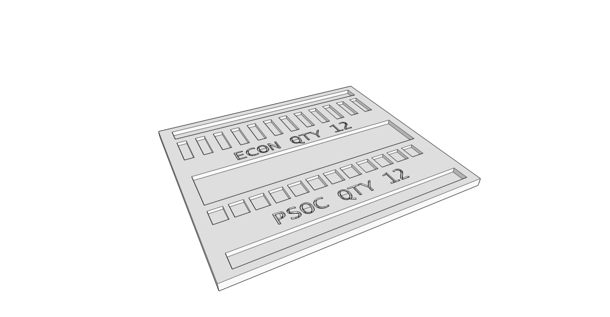
For one of the jobs we are doing I needed two trays, one for the PSOC4 and another for the FFC connector for the LCD. The DP2006-2 is pretty limited in pick and place area so I decided to make a part tray that would hold both parts. First I measured out the metal tray area on the DP2006-2 and looked at the datasheets of the parts for the physical dimensions. Then used SketchUp to draw out the tray. I gave each part .15mm clearance around the maximium size of the part. This takes care of any tolerance issues. If the tolerance is to big then the part can become crooked in the tray and the machine might have difficulties in picking up the part.
SketchUp model of the Part Tray
The Sketchup file can be downloaded here and the STL output for a 3D printer can be found here. I sent the files over to my friend Chris Kraft who printed the model with his MakerGear M2.
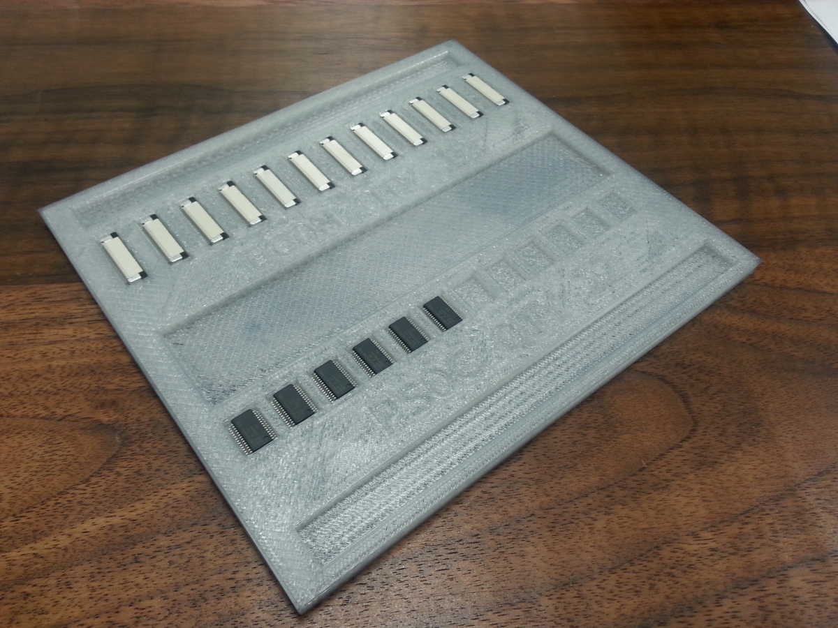
3D printed Part Tray with test squares
Chris sent me the model along with some test squares so I can test the ESD spray paint adherent to the PLA material the part tray was made out of. It adhered just fine to the bare PLA material so I went ahead and sprayed the part tray.
Part Tray in the DP2006-2
So far I have tested it with the FFC Connector and it has worked great! The PSOC4 fit but I have not trained the machine on it yet. I will post a picture when I load them into the machine.
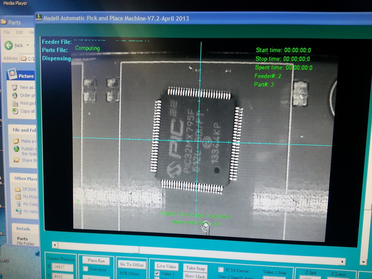
The Pinheck Pinball System uses a PIC32MX795F512L-80I/PT mcu. It is a 32bit mcu running at 80MHz with 512KB of program space. Plenty fast enough for pinball. The only reasonable package it comes in however is TQ-100 package which has a pitch width of 0.5mm. This pushes the limit of the vision system of the DP2600-2 but I managed to get the system dialed in to make the placement.
The PIC32MX795F512L-80I/PT is a tray part so the machine does not pick the part up from a feeder. Instead you line up all the chips in a row and the machine knows where to look for it. Uses the vision system to find and locate the part.
After picking up the chip the machine takes it over to the “Uplook” camera. Here is can make sure the part is oriented correctly and lined up.
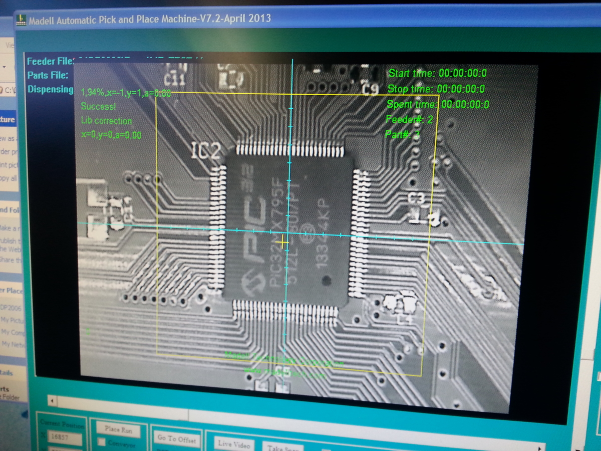
The machine then moves on over to the part location on the PCB and places the part. In the image you can see the dark areas between the shiny leads of the PIC32. The dark areas are the solder mask showing through which means the part was placed correctly and straight.