Nominal automotive voltages range widely. Your circuit needs to handle anywhere from 10V to 15V to properly function correctly. This is a challenge on the power supply side but it is forgotten often on the input/output control side of the circuits.
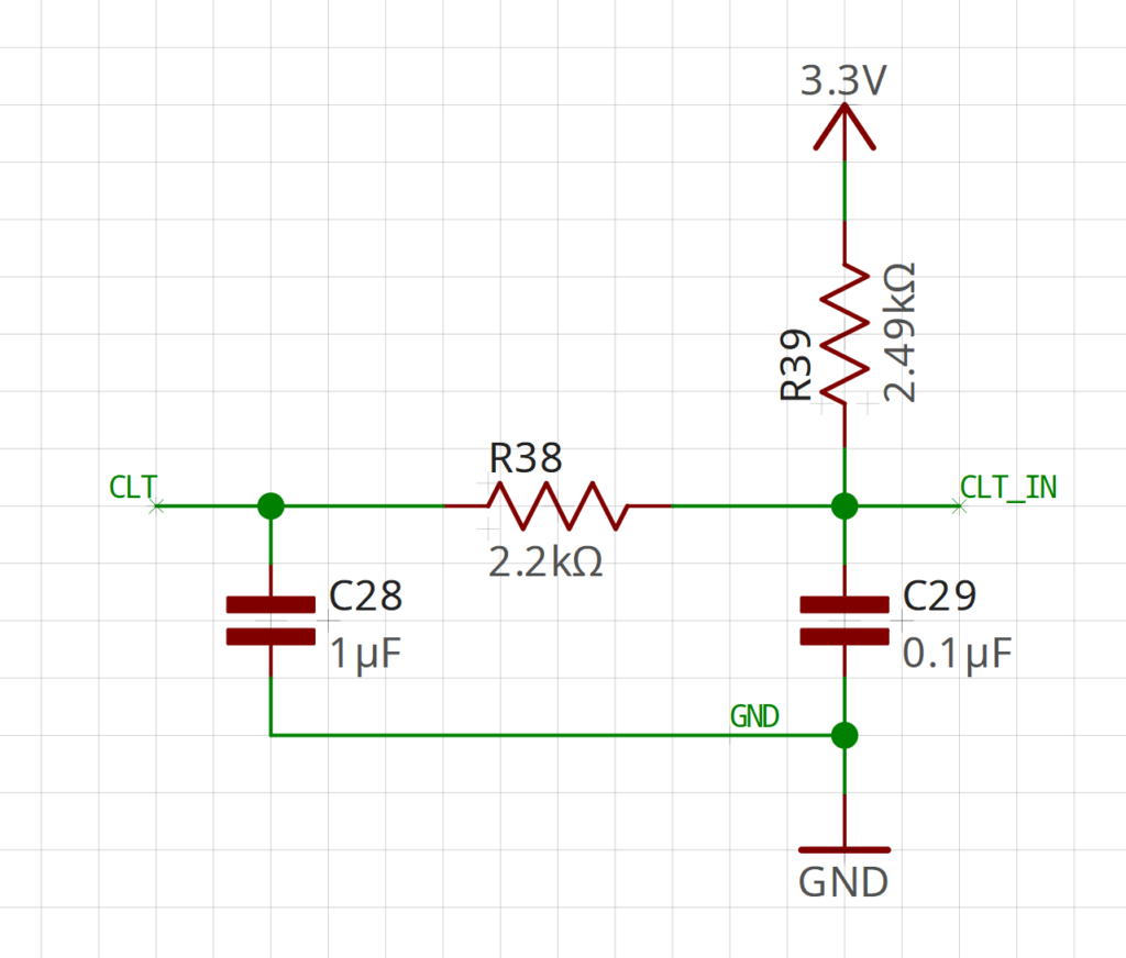
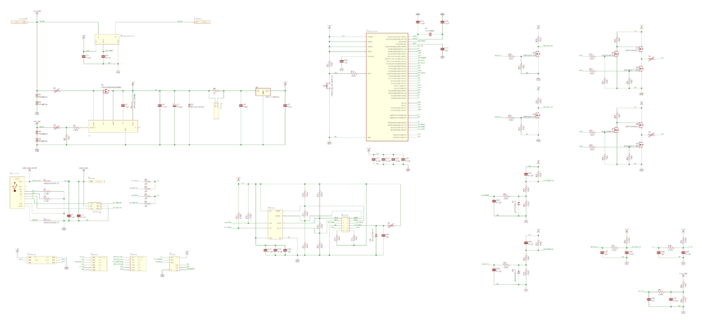
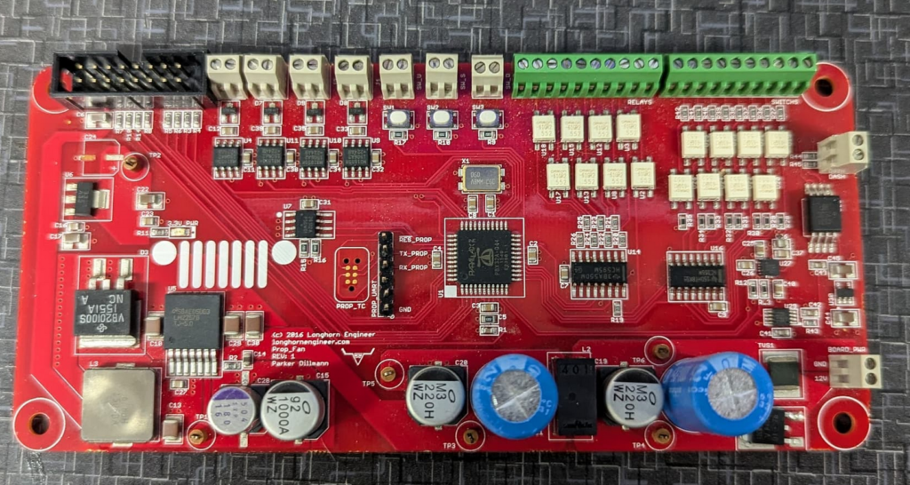
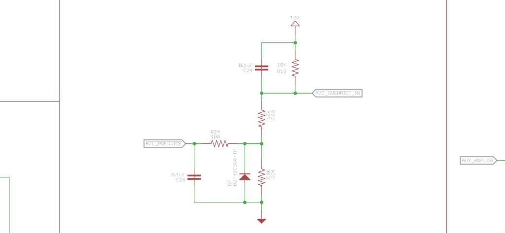
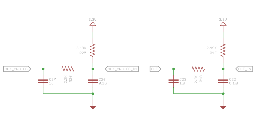
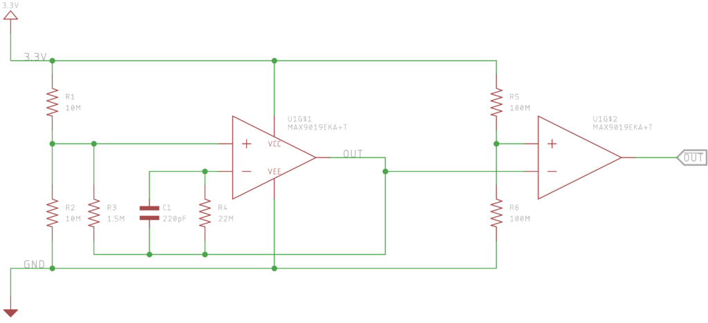
Below is my current digital input circuit for the Cyclone Pulse Wrangler. This is an active low circuit. A switch pulls AUX_DIGITAL_IN to ground. This goes through some filtering and a voltage divider so the 3.3V MCU can safely determine if the switch is activated or not.
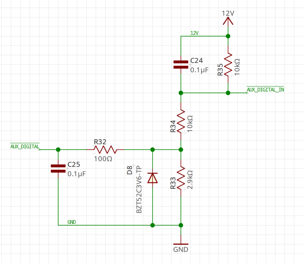
On the MCU side (SAM D21 in this case), there is a threshold on the GPIO input on where the MCU considers the difference between a high or low signal. We need to make sure over the range of the power supply voltage (10V to 15V) that the MCU considers it to be a high signal.
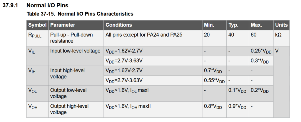
This in page 875 of the family datasheet. VDD is 3.3V in our circuit. VIL and VIH is what is important here. VIL is 0.99V and VIH is 1.815V. This means if the voltage on the GPIO pin is high and drops below 0.99V then the MCU will register that as a low. If the signal is low and rises above 1.815V then it will consider it a high. Between these voltages it doesn’t initiate a state change.
We need to check to see our circuit stays above 1.815V output across the entire span. LTSpice is a goodish program to do this
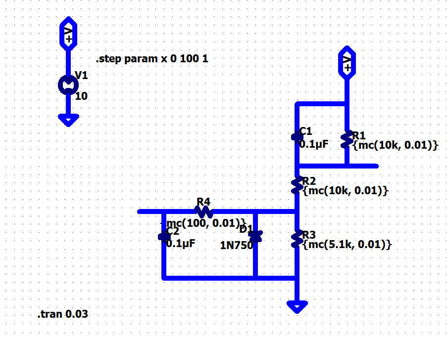
Above is the circuit in LTSpice. Stepping the +V from 10V to 15V gives the following output.
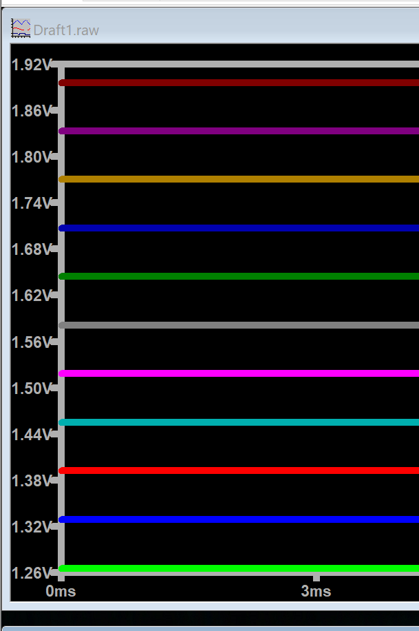
Well that isnt good! At 15V we get ~1.9V but at 10V we get ~1.26V which is in our gray zone! Lets change the 2.9K to 5.1K (R33) and see what we get.
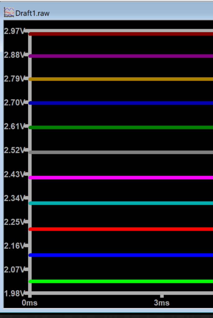
OK! Everything is in our deterministic range for a high signal! But lets check for resistor tolerances. Running a monte carlo simulation with 1% resistors gives us the following outputs. 10V rail and then 15V rail.
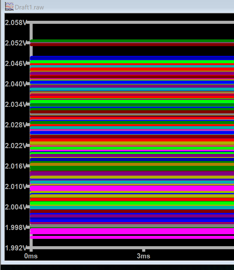
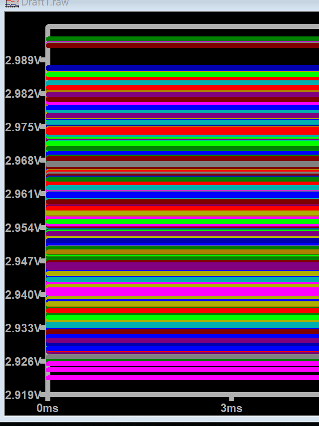
Well that looks good as well. Digital input should operate fine on the Cyclone Pulse Wrangler!