
For the Cat Feeder Unreminder, I am going to pivot from using LEDs to indicate the “feeding” status and use a TN-Effect Display instead. These displays are much lower power then illuminated LEDs but they require slightly more circuitry to drive.
TN LCDs run off low AC voltage from around 3VAC to 6VAC depending on the screen. The one I picked, Varitronix‘s VI-422-DP-RC-S, operates over this range. They are not particular picky about the quality of AC voltage, just that it has zero DC offset. Driving the displays with square waves seems common. Anything north of 50Hz should do as well.
This application note from NXP shows how to drive these displays from logic level DC devices like microcontrollers.
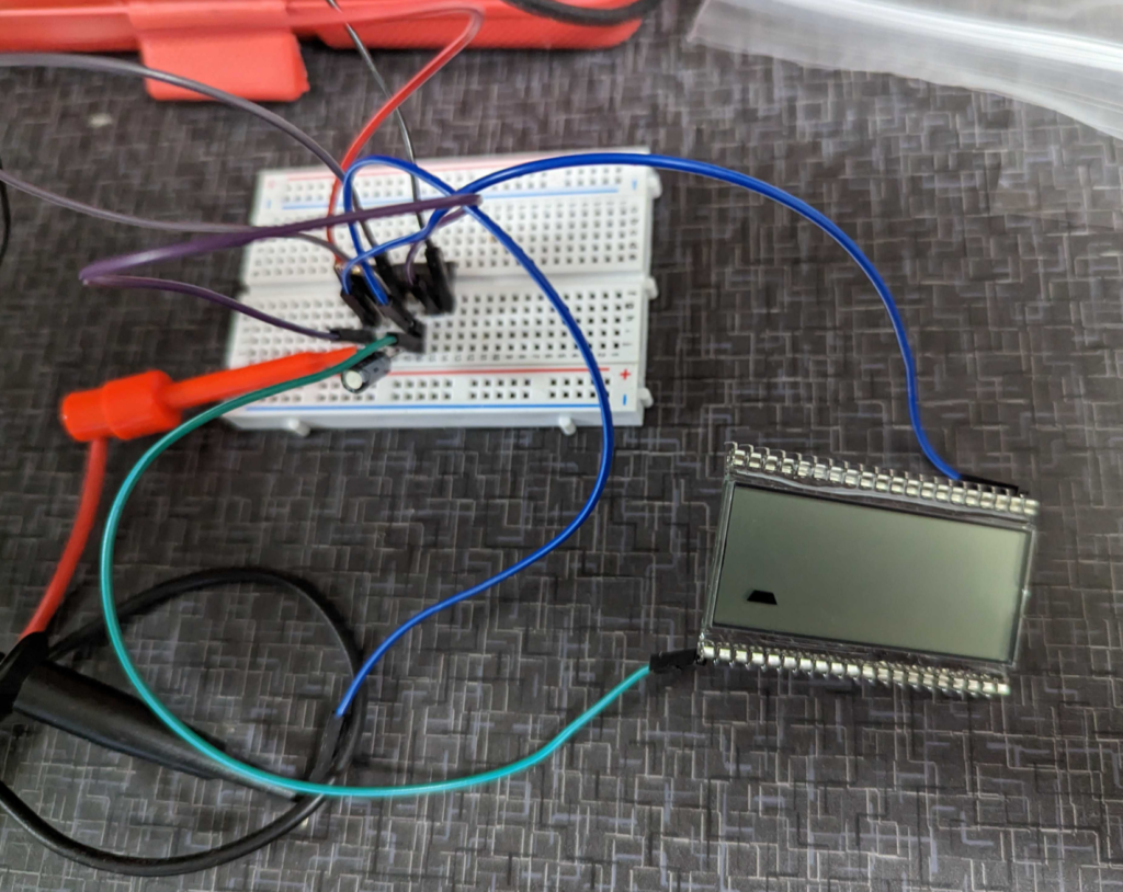
Looking in my spare parts bin I found some old CD4049 hex inverters that I made into a simple RC based oscillator.
I used a 0.1uF capacitor and a 100K ohm resistor. Should get the oscillator to jiggle around 70Hz. Then I fed the output of the oscillator into another inverter on the CD4049. This gives me two square waves that are out of phase which will give us the AC voltage we need!
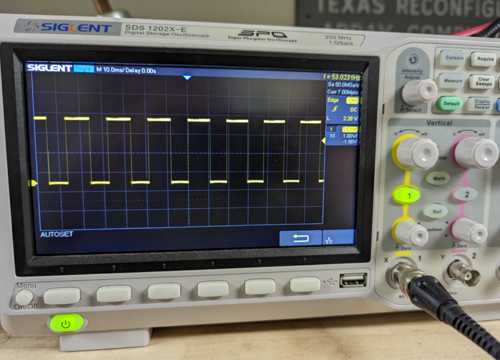
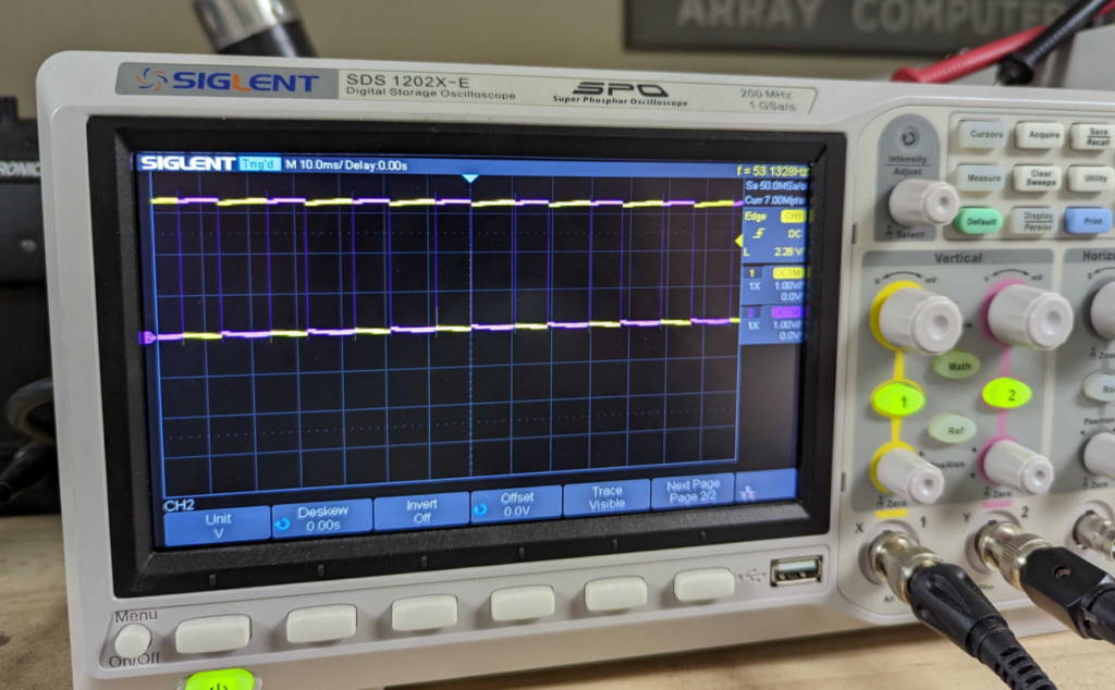
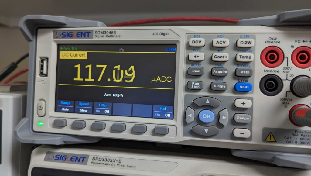
This works great! However the downside is this oscillator uses ~120uA at 3.3V without driving the Display. The display takes sub 5uA to drive so this is a big part of the power budget!
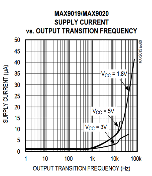
We will need another way to generate the AC voltage! Metacollin from the MacroFab Slack Channel suggested using a low power comparator in a relaxation oscillator configuration. This will get us to around 1uA in current draw if we use a MAX9019 dual comparator chip.
I am also looking for a way to measure currents that low. My Siglent SDM3045x is a bit out of its league at this point!