The cabling for the fan arrived today. 8AWG wire and the appropriate cable lugs to attach it to the battery.
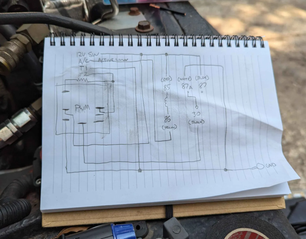
This is the PWM controller I am going to use while I test this fan out. It seems built well but the only problem is the A/C override is active high (apply 12V). This is the old school way of running your electric fan when the A/C is running. Essentially, you would just tie this to your compressor clutch on the A/C. Fan turns on when the compressor is running. This isn’t the correct way to do this though. When you are at highway speeds you don’t want the fan to spin up just when the A/C compressor is running. The airflow from driving should be more then enough to cool the condenser.
To activate the fan for the A/C system a trinary switch should be used on the high side of the compressor. This is basically a high pressure safety switch and a lower “fan enable” switch built into one component.
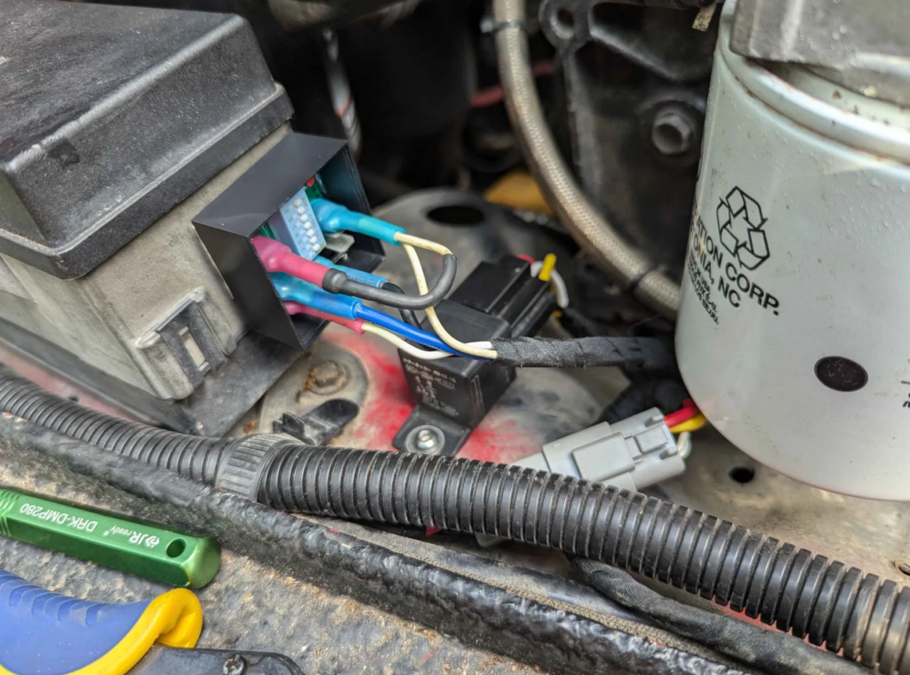
These trinary switches switch to ground to enable the fan for the A/C. Exact opposite of what this PWM controller wants. I flipped the logic with a relay.
I currently have the PWM controller programmed to start spinning the motor at 196F. Then full speed is set at 225F. As the temperature swings during that range the fan goes faster.
Current testing shows this fan is amazing. It was 99F today. With A/C on max, the fan was running at the slowest speed and kept the engine at 198F. The old fan would barely keep it at 220F.. routinely peaking at 230F.
The wagoneer needs one of these fans! Next week I will be taking the Jeep on road trip and will be able to test heat soaking the engine, highway cooling, traffic, ect. and really see what this fan can do.
The PWM controller is set to 100Hz PWM with negative polarity. Range of pulse swing is 15% to 90%.
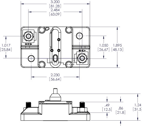
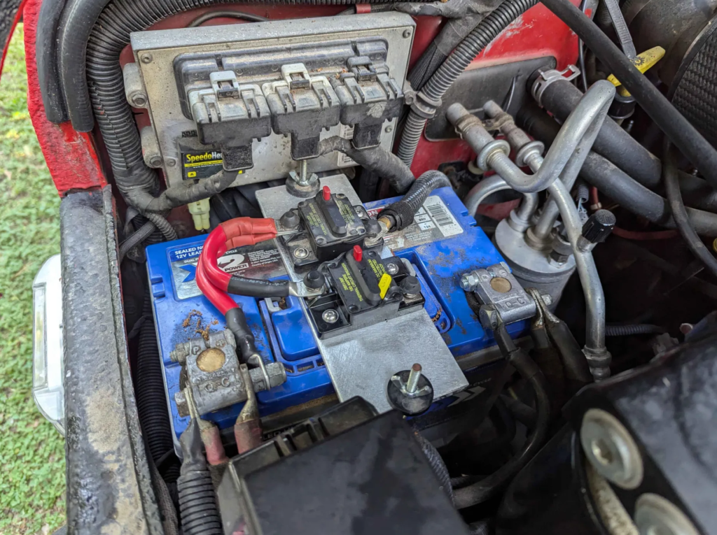
That big 850W fan needs some big wires and a way to safely deliver the current. I am going to use a 100A automotive breaker by Blue Sea. I’ve been using one for the rest of the Auxilary Power on the Jeep for years now and its been working great.
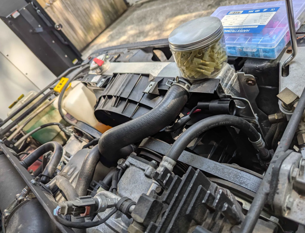
I cut a new battery hold down and mounted the breakers on top. One goes to the rest of the auxiliary system and the new one (its clean!) will route to the fan.
Next is to wire 8AWG wire from the breaker to the fan. I also have an off shelf PWM fan controller I will use till I get mine designed and built.
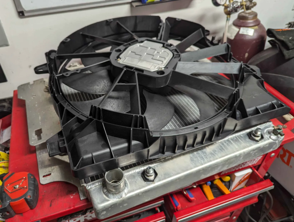
I have been running different combinations of mechanical and electric fans over the years to try to keep the TJ jeep cool. I have been running a Delta Pag 18″ brushless fan with much success for the past 2 year. The fan kept the engine cool at all conditions but had longevity problems. Currently the fan makes tons of bearing noise now and keeps killing the motor controllers. Lets get rid of it and go with something that is cheaper and OEM spec.
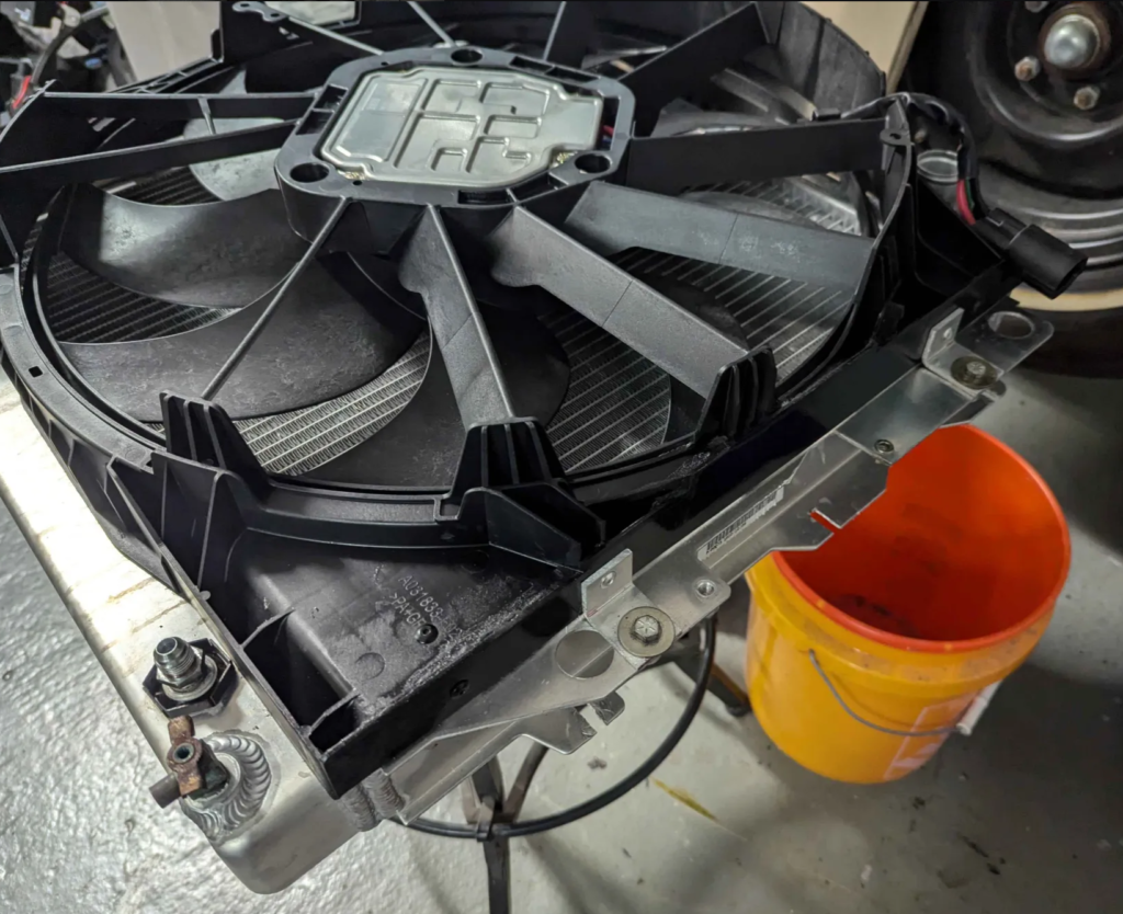
Top is the new fan I am going to try. It is an OEM fan for a JL/JT Jeep in Mojave Trim or Heavy Duty tow package. This fan is rated for 850W with 20″ of blade. Part number 68272755AD. These fans are used on lots of modern vehicles ranging from dodges, Jeeps, Mercs, BMWs, ect. Really easy to find. They all have just some variation of plastic shroud on it. The old/current fan is a ~360W 18″ fan for comparison. The new fan will work… or else ;)
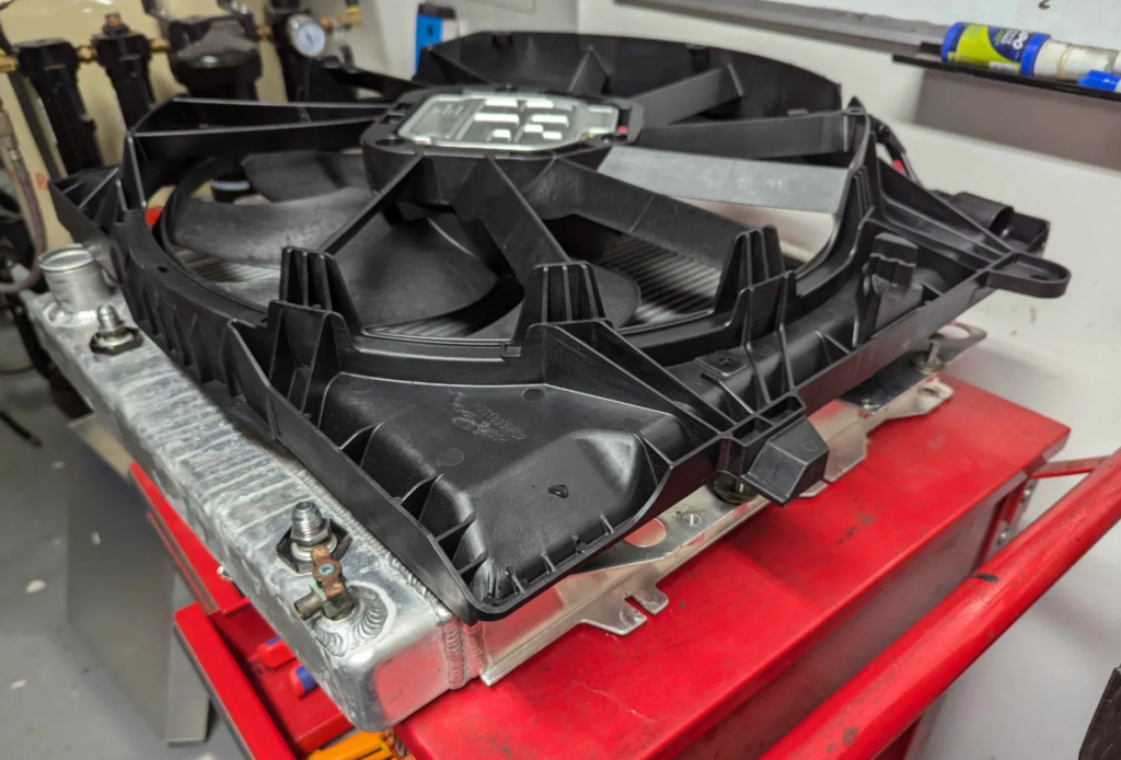
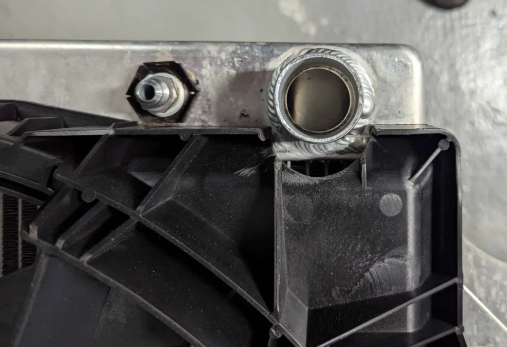
Here is the new fan set over the radiator. It is too large but I think I can trim the shroud to make it fit.
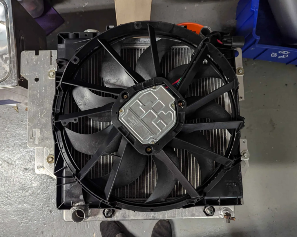
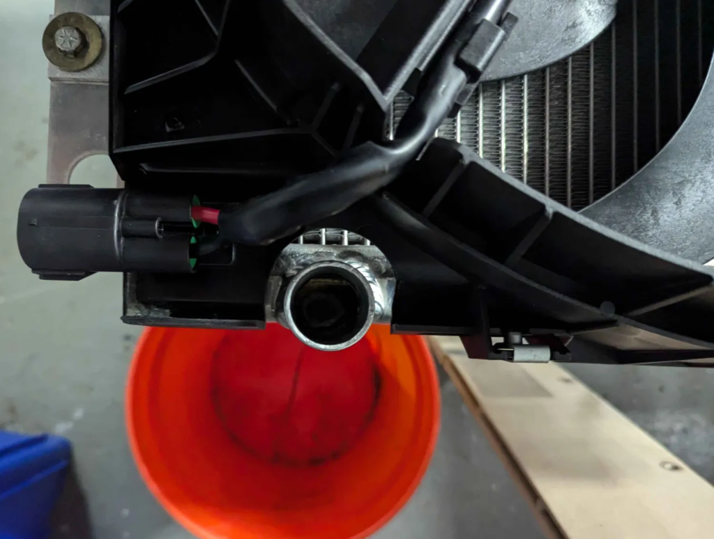
I trimmed the shroud for the hoses and then reduced the width and epoxied in an aluminum sheet cut to fill the opening. Then made some little aluminum brackets to mount the fan to the radiator.
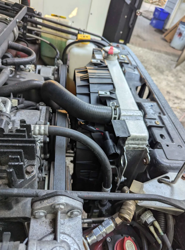
Fan fits! Takes up more space then the delta pag one but still clears everything. Will need a PWM controller for this fan. That is next.
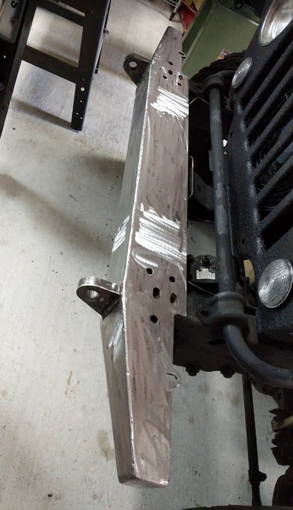
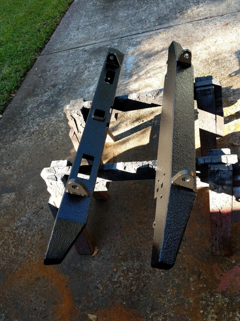
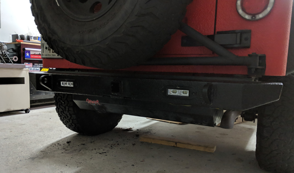
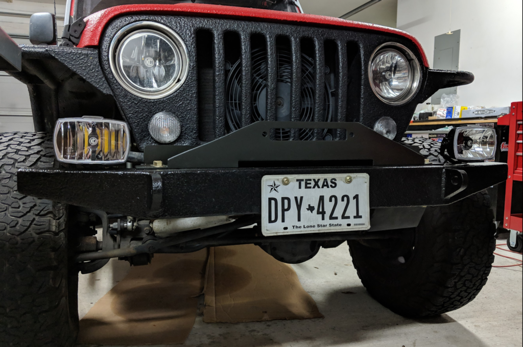
Time to get rid of the stock bumpers for the red jeep!
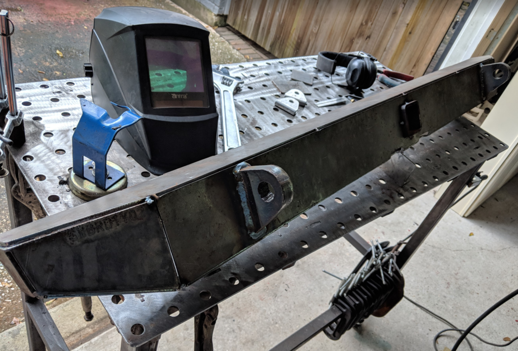
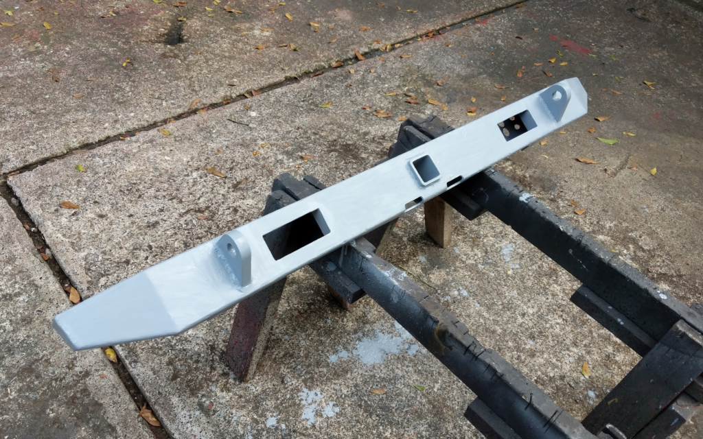
Every since I bought the Jeep I wanted offroad bumpers but never got around to it. I wanted some “simple” looking bumpers and I found a kit from JCR Offroad that would allow me to get some practice in with the welder! Front Bumper / Rear Bumper
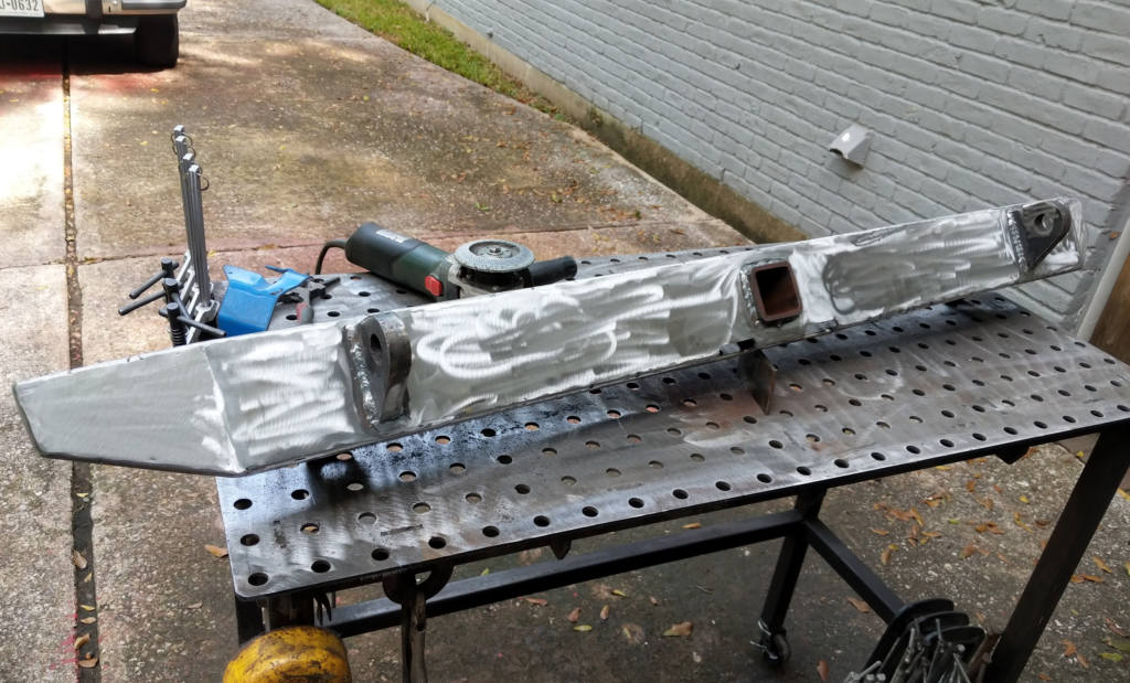
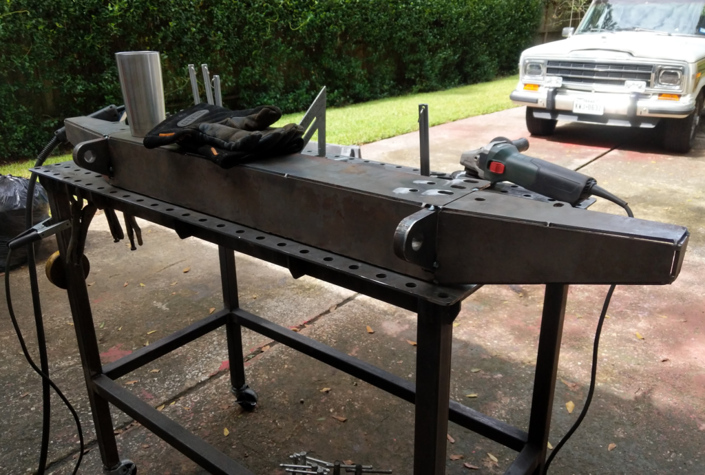
What I really like is that they are cut out of 3/16″ steel, have a low profile look, tow rope hookups, and the rear has an integrated 2″ receiver which is perfect for pulling small trailers around.
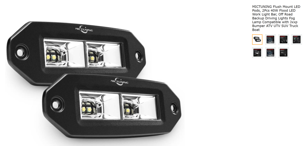
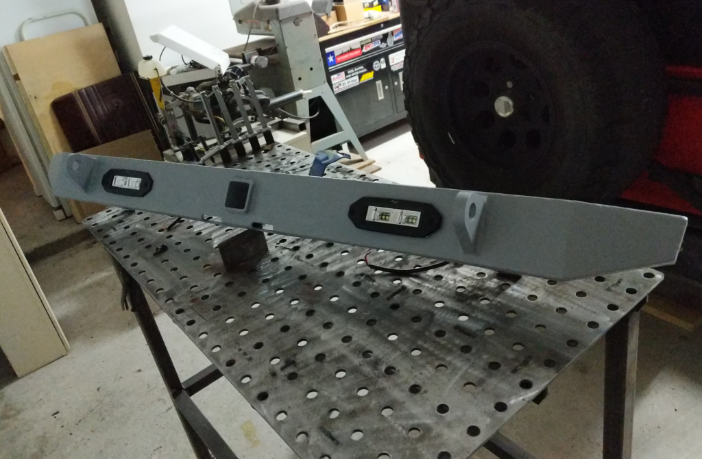
For the rear, I added cutouts for rear back-up lights. These are the ones I bought on Amazon.
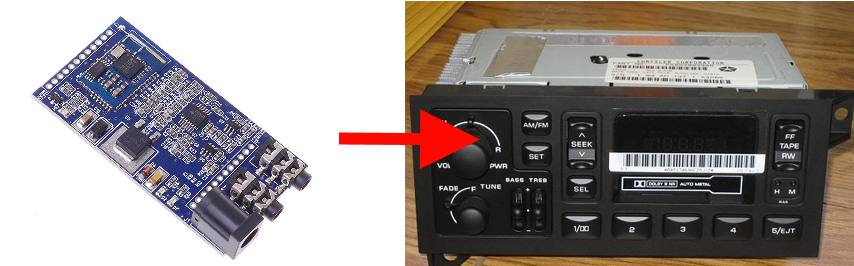
I have been working on my old 1999 TJ Jeep and I always wanted to have Bluetooth connectivity in for the stereo. I could have bought an after market head unit but I never really liked the look of them and they tend to be easily stolen out of the Jeep (softtop!). The stock head unit matches the dash and is less likely to be taken. Thus the solution was to hack in a Bluetooth module into the radio!
First I bought a used radio on ebay. Part number for the radio was P56038933AB and I was able to pick one up for $25 as I wanted to keep my radio functional in the Jeep till I got the Bluetooth working. Then I picked this module on amazon. I chose this module as it had a wide input voltage, every single connection and signal was brought out to a header, and it had good reviews.
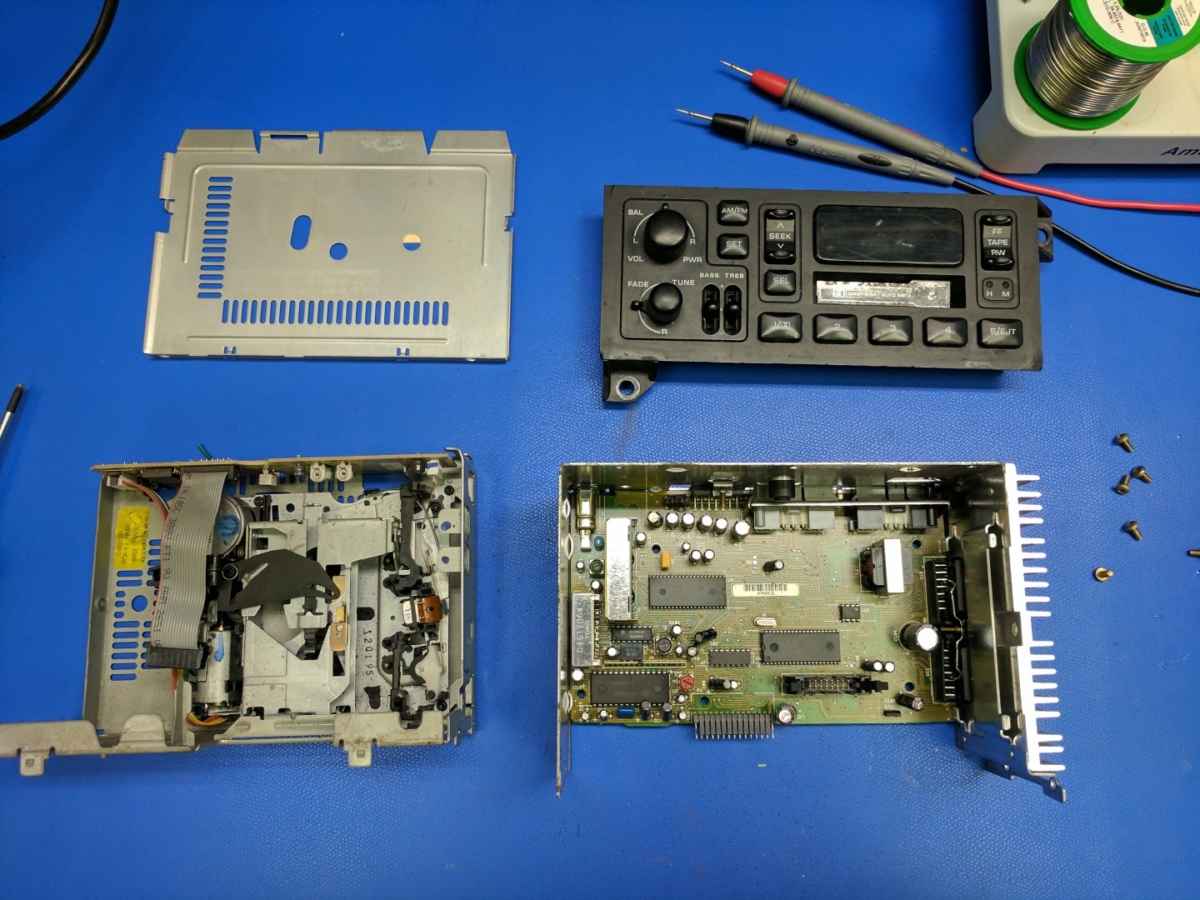
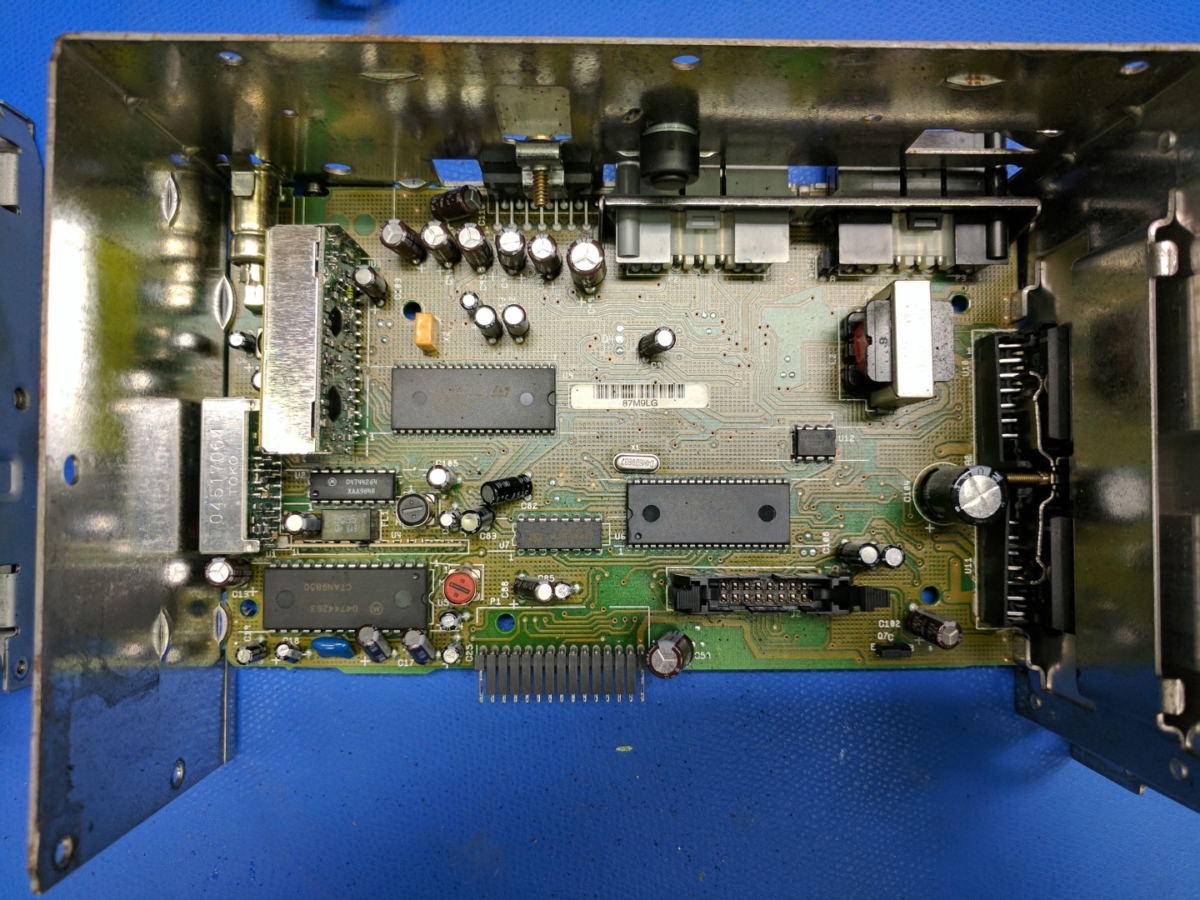
Next I opened the radio. It had T15 Torx (jeep thing :| ) machine screws that held it all together. Took it apart all the way to the bare radio.
Next to figure out how to get the Bluetooth signal injected into the radio! Most people that do these kind of hacks just blindly poke around the radio till they find and audio signal and then inject there. This is fine but I wanted to make sure I was getting the best audio quality out of my cheap Bluetooth module and early 90’s designed, base model head unit. I also wanted to keep the volume knob on the radio functional. This meant injecting the Bluetooth signal in the circuit before the power amplifiers and before it was gained for volume.
To figure out where to inject the audio. I first wrote down all the IC Manufactures, Part numbers, and Package size. Clicking the links will show an image of the IC.
Next I started searching for stuff like “ST Audio DIP42” into google. After finding promising datasheets, I then verified their pinouts buy tracing the power and ground sources in the radio. Here is the cross reference of what I was able to find. I also found this interesting PDF which is a early 90’s listing for ST Micro parts. I was able to find the TDA7340S IC with it.
The IC that does the sound muxing, volume, and tone control is the TDA7340S and I figured this would be the best place to inject the Bluetooth audio signal.
Above is the block diagram. After the audio mux the signal travels to an external effects loop which consists of in series 1uF electrolytic capacitors. Then the audio signal travels into the volume and tone control parts. Perfect! If I inject the audio right before the capacitors I will retain the volume and tone control of the radio.
I thought about using the unused PHONE IN and then using a MCU to sniff the I2C buss and inject the right commands to switch it to that input but figured that would be more work then just injecting in the effects loop.
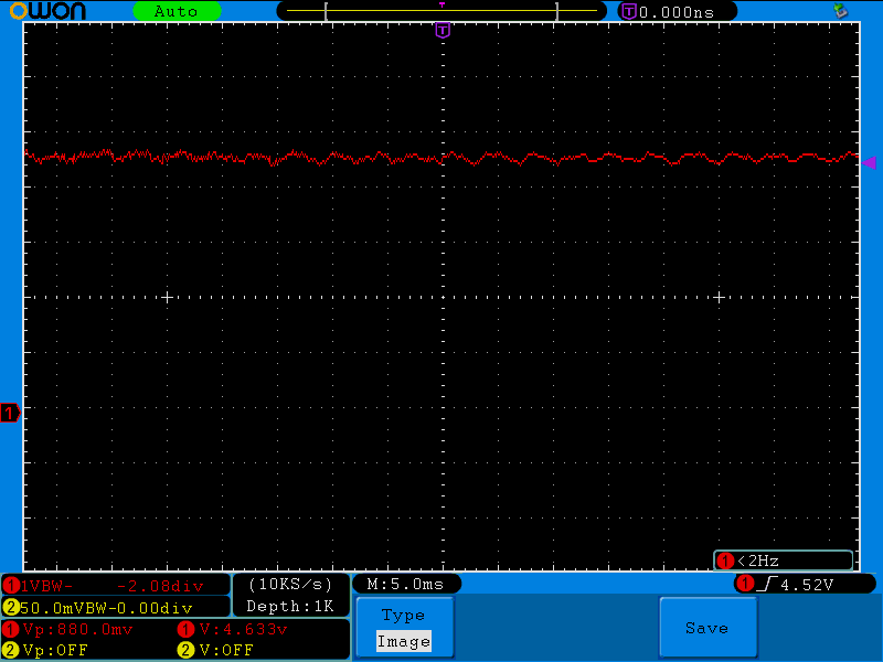
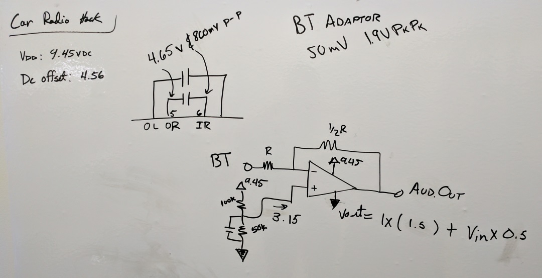
The next part is to make sure the signal from the Bluetooth adapter is compatible with what the TDA7340S is expecting. At max volume on my phone the Bluetooth adapter outputs a ~50mV DC offset signal with a ~1.7V to ~1.9V Pk-Pk. The signal in the effects loop was 4.65V DC offset signal with a 800mV Pk-Pk.
Bluetooth Module output at max volume.
Output of the TDA7340S effects loop. This would need to be matched to ensure compatibility.
Since these signals are different I needed to adjust the signal of the Bluetooth adapter. I would need to apply a DC offset and then negative gain the signal from the Bluetooth signal. The opamp circuit below should do the trick. The feedback circuit is set to half gain and by applying half of VCC (via a voltage divider) to the other input of the opamp we can DC offset the signal.
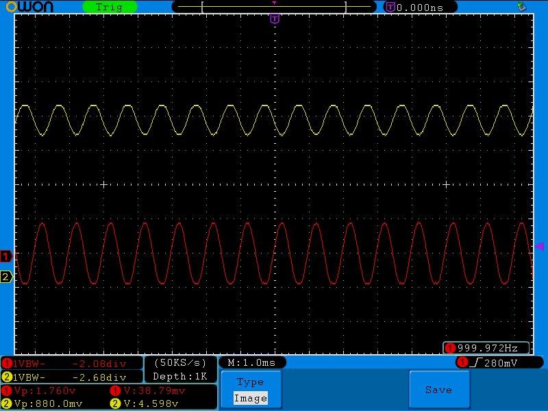
I tested it by having my phone play a tone via a tone generator app called “Frequency Sound Generator”. Signal below.
The input is in red and the output is in yellow. Signal now matches closely to what the TDA7340S expects their to be in the effects loop!
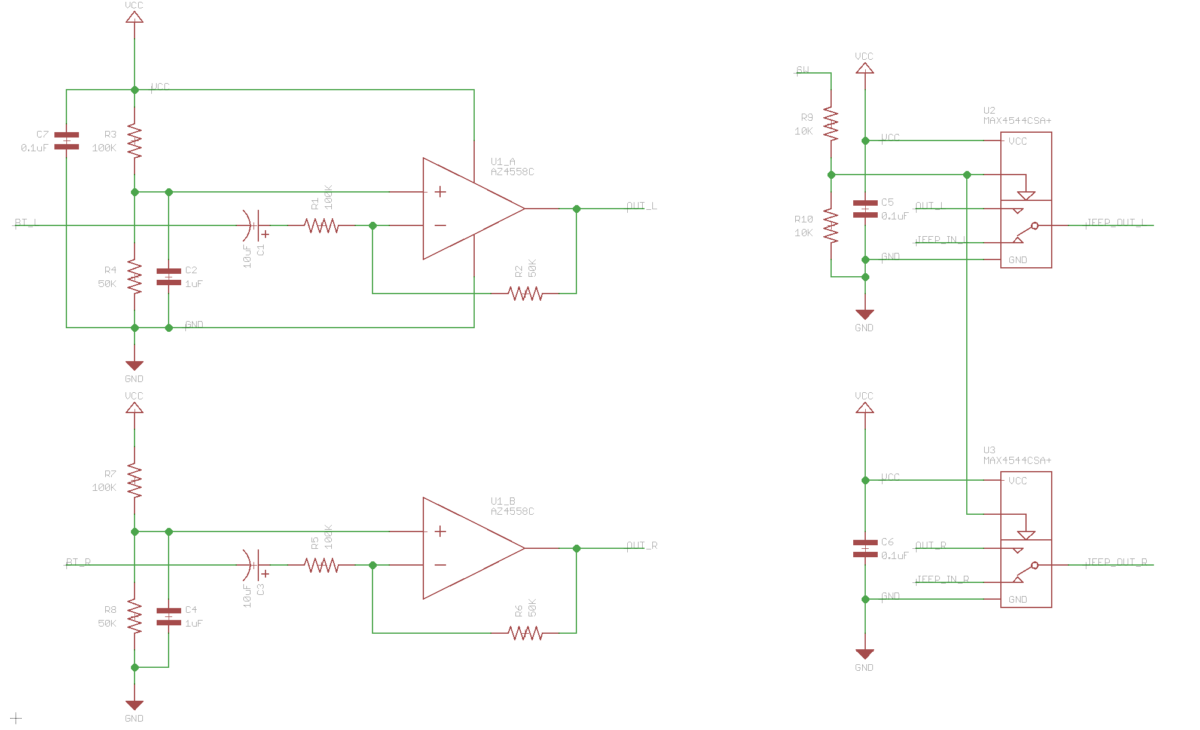
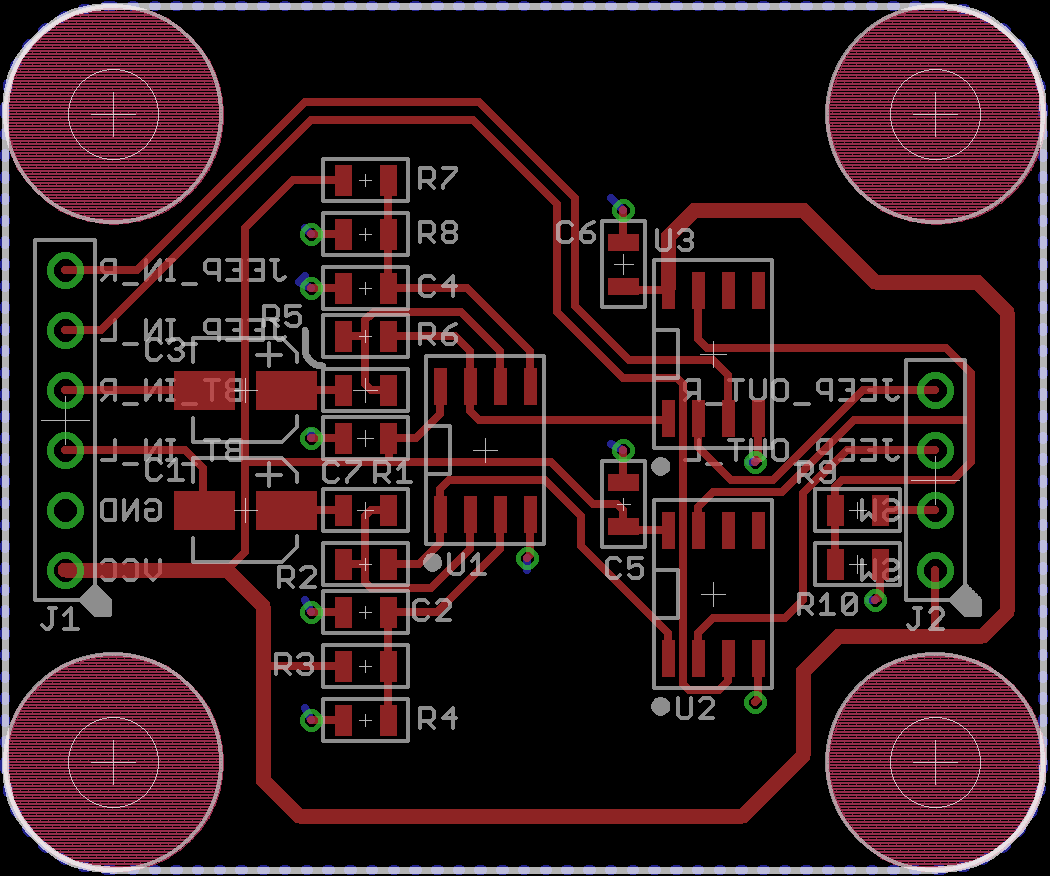
Then to switch between the TDA7340S signal and the Bluetooth signal I found an analog switch IC made by Maxim, MAX4544CSA+. The opamp I decided to use was a AZ4558C. I decided to use it because it is a decent audio amp and fairly inexpensive. Lastly, since its stereo we need to double everything. Below is the schematic and layout I did in Eagle.
The files for the board can be found on my github. I uploaded the files to MacroFab and ordered the board.
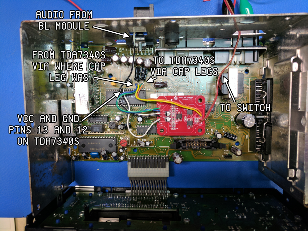
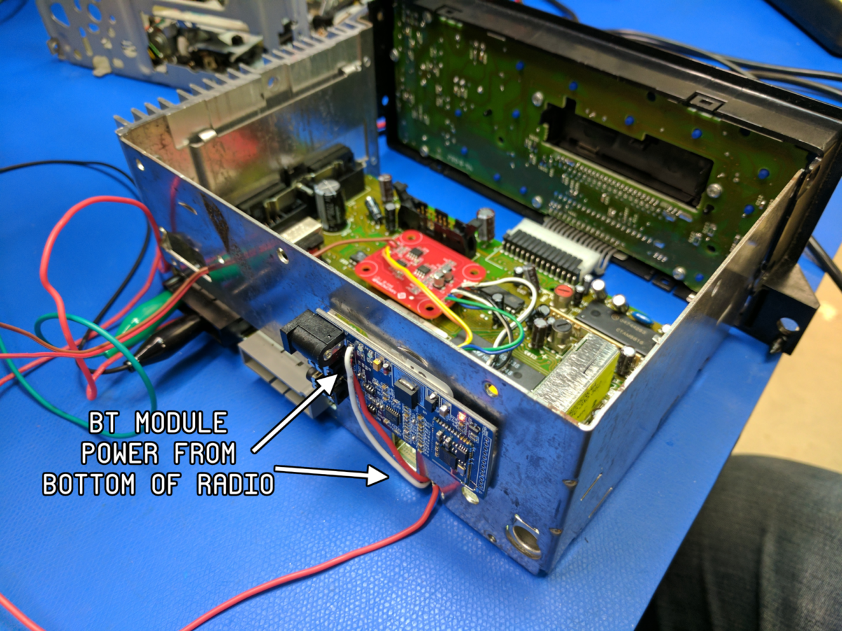
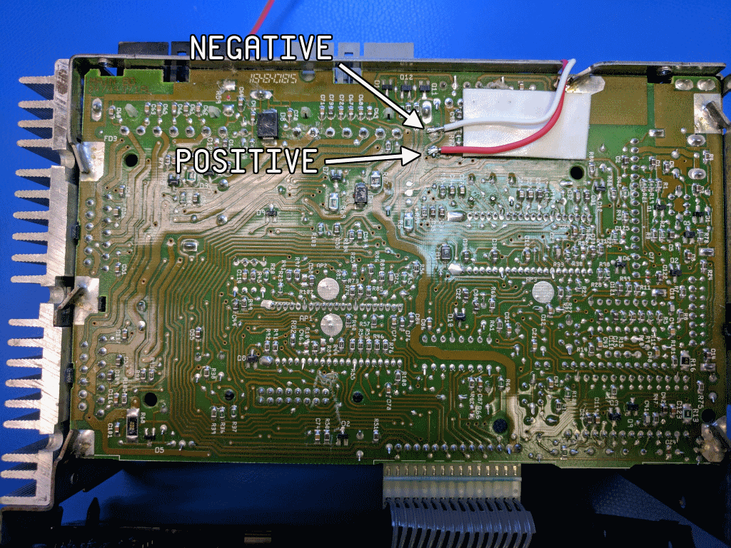
I then soldered the board into the radio. I desoldered one leg of the the effects loop 1uF caps which are designators C112 and C113, then soldered hook up wire on the legs of the capacitors and into the hole in the PCB. The power for the Bluetooth module is pulled from the bottom of the radio. To switch the audio from the TDA7340S to the Bluetooth the input of the MAX4544CSA+ is pulled up. A switch on the dash will be used for this. See image below for how everything is hooked up.