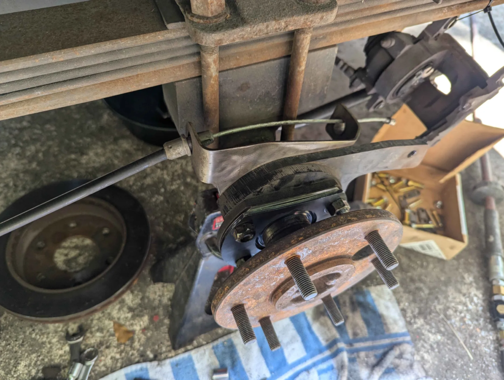
The wagoneer has started to make noises in the rear driver side area. It sounded like shaah shaah shaah. Applying brakes didn’t change the noise. Probably bearings?
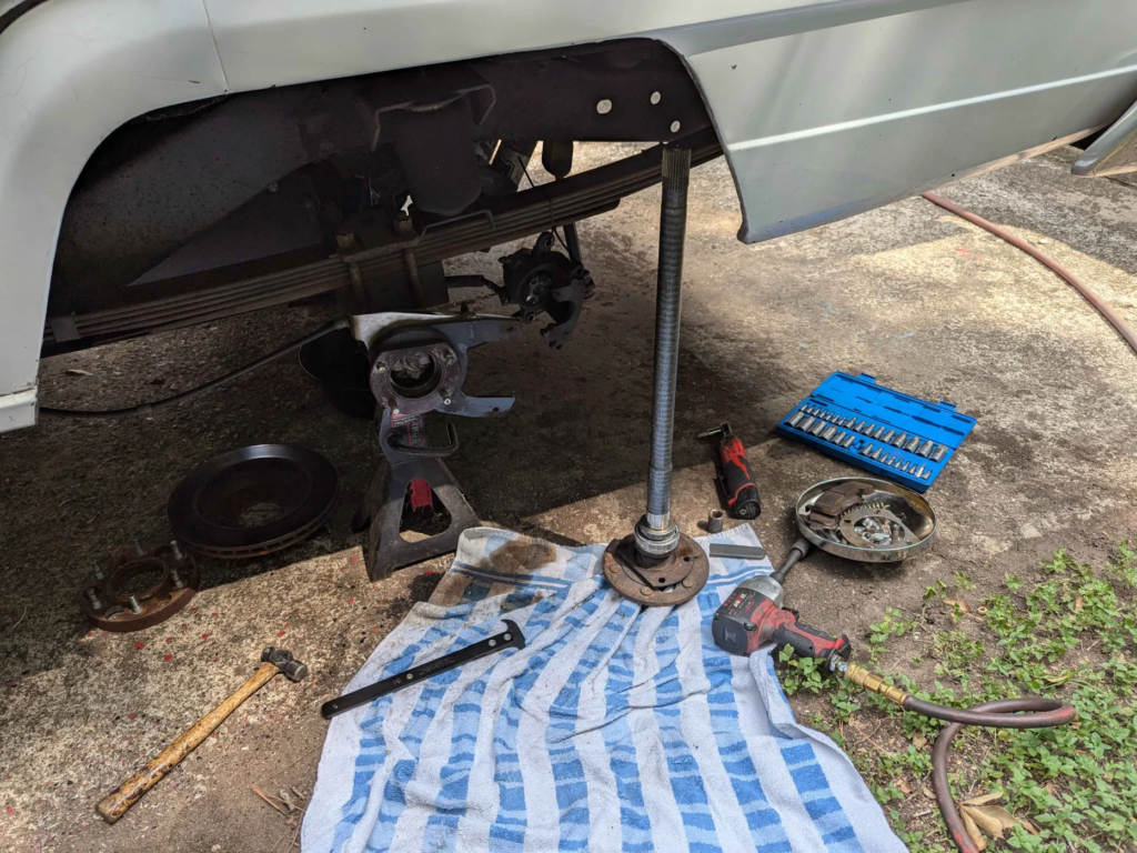
I tore down the driver side and found that the axle flange had more then 1/8″ of axial play!
These are the references I am using to help reassemble everything
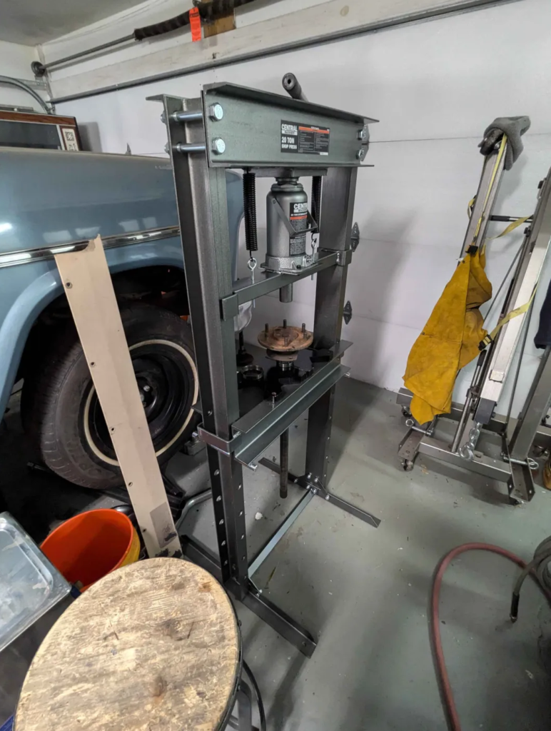
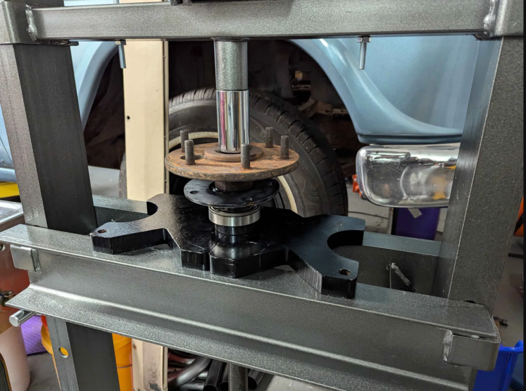
Disassembly is easy. Reassembly requires a press to push the bearings onto the axle shaft. A trip to Harbor Freight and some assembly later, a 20 Ton Press appeared in my garage.
After reassembly, the play in the bearings was gone and there was no noise on the test drive! Another thing fixed.
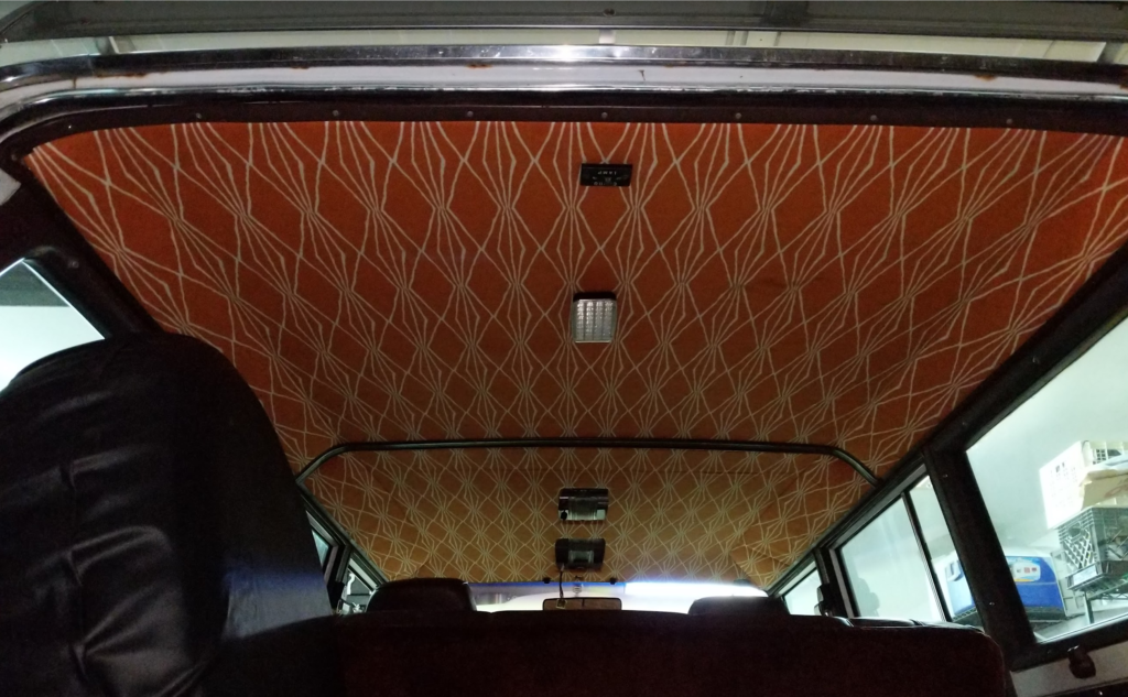
The original headliner for the Jeep Wagoneer was moldy and sagging. To fix this, I had to build my own complete headliner. I didn’t take any photos during the build but I will explain the process and materials I used.
Materials
Coroplast Plastic Sheeting
2-4mm thickness, thinner is better
This is the new backer material for the headliner, it is the same material political yard signs are made out of
You can order this from a local sign shop
Foam-Backed Automotive Headliner
Try to find a Made in the USA material as the imported stuff tends to fall apart
DAP Products Weldwood Landau Top & Trim HHR Solvent Type Spray Grade Contact Adhesive
You want this stuff and not the kind already in spray cans
Need a spray gun that can handle the thick glue, I used an HVLP gun with a 2.0mm nozzle
You want a really good paint respirator when spraying this stuff
A high quality fabric you want to put over the foam
I went to my local fabric store and picked enough out to cover everything
Make sure its wide enough!
Process
Take the old headliner out of the vehicle.
Remove what is left of the foam material off the old backer material. Be careful to keep the original backer in tact, it will fall apart if you let it.
Use the original backer as a pattern and trace it out on the Coroplast. Orientate the Coroplast’s corrugations so they go lengthwise (Front to Back) to the vehicle.
Cut out the Coroplast with a utility knife.
On the parts where the Coroplast needs to bend or curve, cut through only through the top side of the Coroplast. This way it can bend or curve downwards. You might need to make multiple cuts to get the curve to match the original.
Lay out the headliner foam and cut it to match your Coroplast, leaving about an inch all around the border.
Spray down the contact adhesive in sections and press the headliner foam into the Coroplast. I tried to do it without stretching material.
Let the contact adhesive dry.
Trim the headliner foam to match the Coroplast.
Lay your fabric over and trace it out, again matching your headliner and leaving about an inch all around the border.
Spray down the contact adhesive in sections and press the fabric into the headliner foam.
On the edge of the fabric, glue this with the contact adhesive to the backside of the new Coroplast backer. You might not be able to fold over the edge if you are using thicker (4mm) Coroplast as it wont fit into your trim pieces.
Part of rebuilding the suspension for the Jeep Wagoneer was adding air springs above the rear leaf springs to prevent it from sagging when loaded. Wagoneers suffer from “wag sag” when the leaf springs wear in and I wanted to prevent that and help keep the wagoneer level when loaded with fire wood or whatever I was hauling.
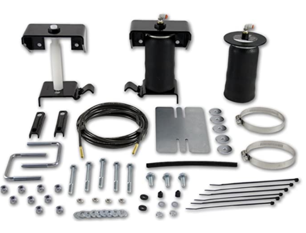
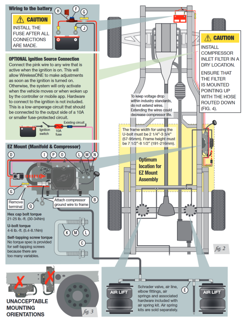
I choose the following AIR LIFT kits that seemed to work out ok for me.
AIR LIFT 59507
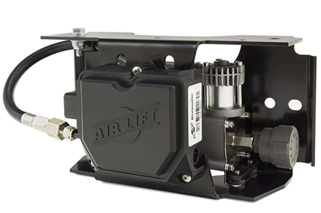
AIR LIFT 25980EZ
The AIR LIFT 59507 is the kit with all the brackets and air bags. AIR LIFT 25980EZ is a air compressor with controller that allows you to adjust how much pressure is in the air bags.
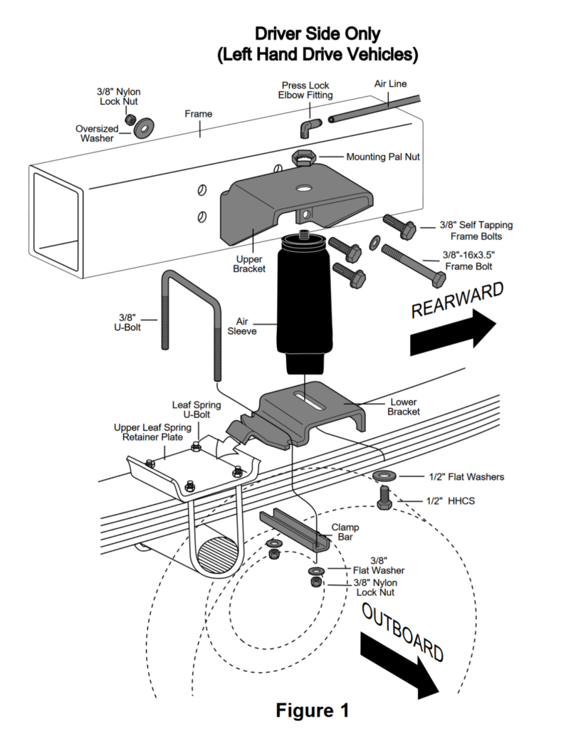
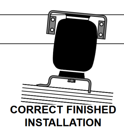
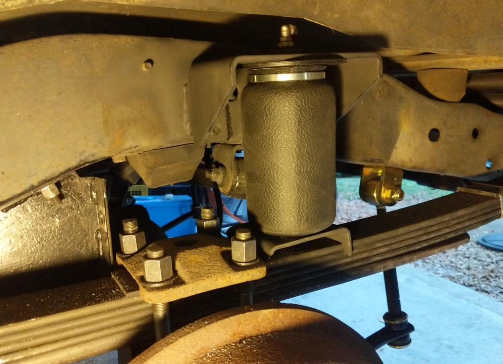
This is the typical install setup for the air bags. This didn’t work out for me though. The Lower Bracket is supposed to rest over the leaf spring retainer plate and bolt down with a u-bolt but I didn’t have clearance for the added u-bolt and the retainer plate was not shaped in a way that allowed the lower bracket to “hook” on to it.
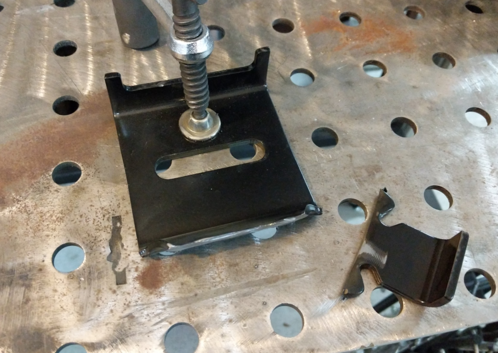
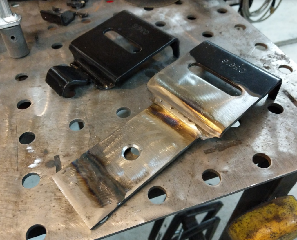
First thing I did was modify the lower bracket by modifying it to be mounted under the retainer plate. Cut off the tab that is supposed to slip over the retainer plate.
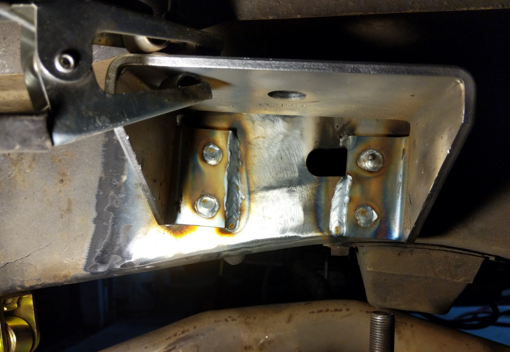
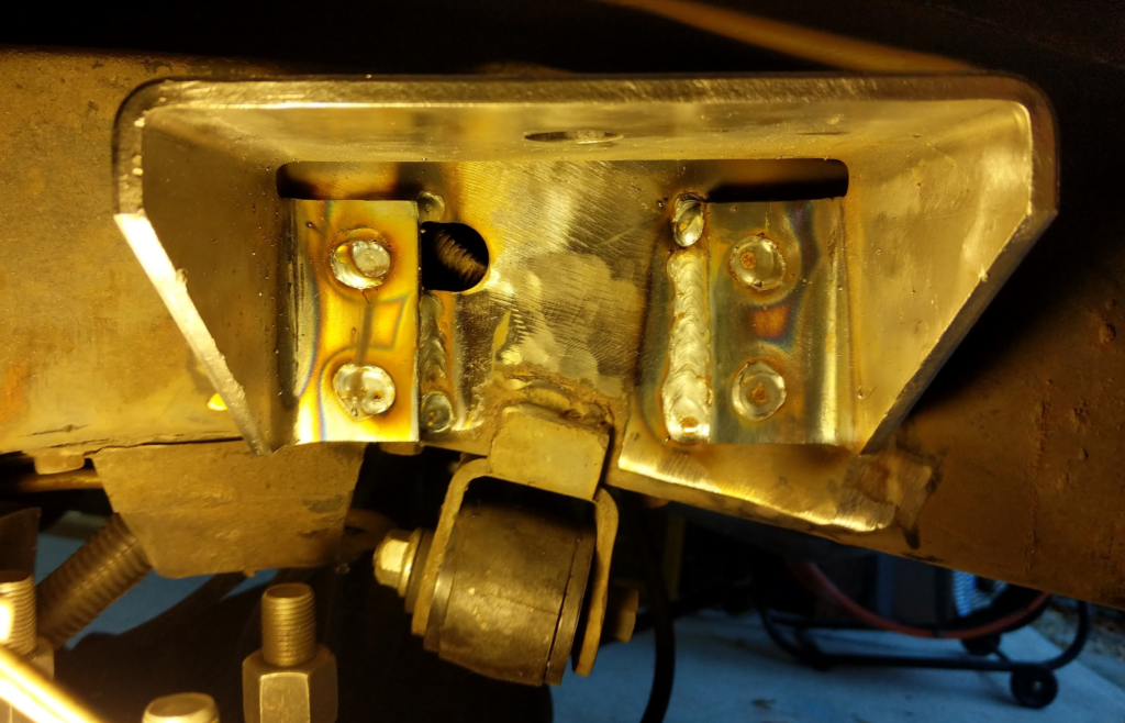
Then welded on a new tab with a hole drilled in it. This hole locates on the leaf spring pack bolt. Spray with some paint to keep the rust away. Bolt up the u-bolts and lower bracket for the air ride so we can mock up the upper bracket. The kit comes with a plastic rod with threads on it so you can set the height of the upper bracket. It has some adjustment and I set it close to the longest it could be since the wagoneer has lots of up travel in the rear suspension. Make sure the suspension leafs are compressed and at ride height when you are doing this. The upper bracket also needs to be parallel with the lower bracket.
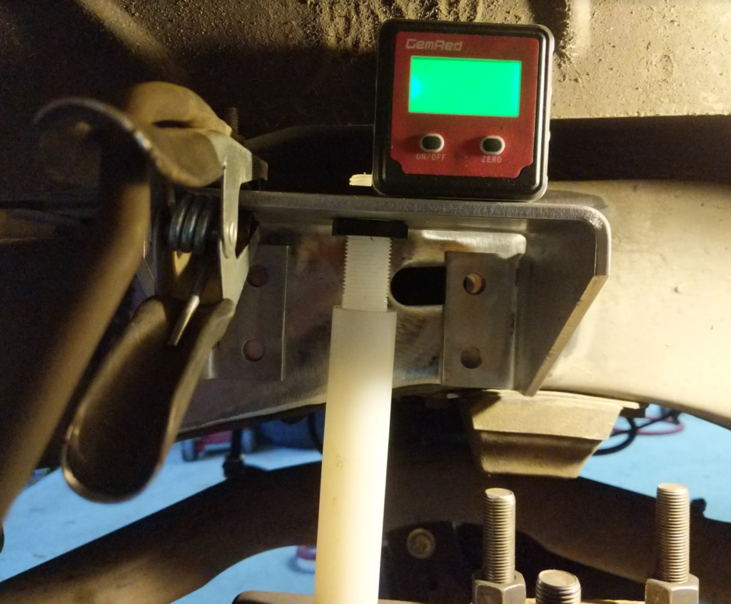
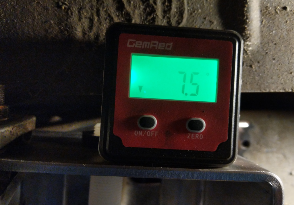
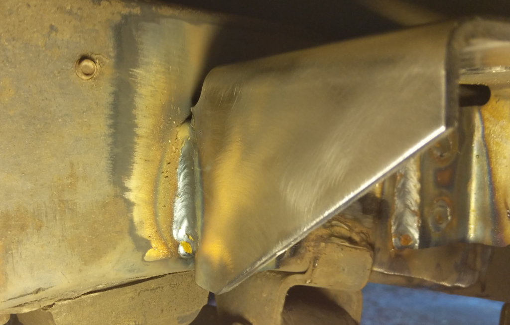
I decided to weld the brackets in when one of the bolt holes overlapped a hole in the frame. Wire brushed the paint off the upper bracket and the frame. Used a angle finder to make sure the upper bracket was parallel with the lower bracket and tacked and welded in the bracket. My upper bracket ended up being 7.5 degrees tilted downwards towards the front of the vehicle.
Coat it in paint and install the bag. Here you can see how the lower bracket wouldn’t mount onto the spring retainer plate in the normal way.
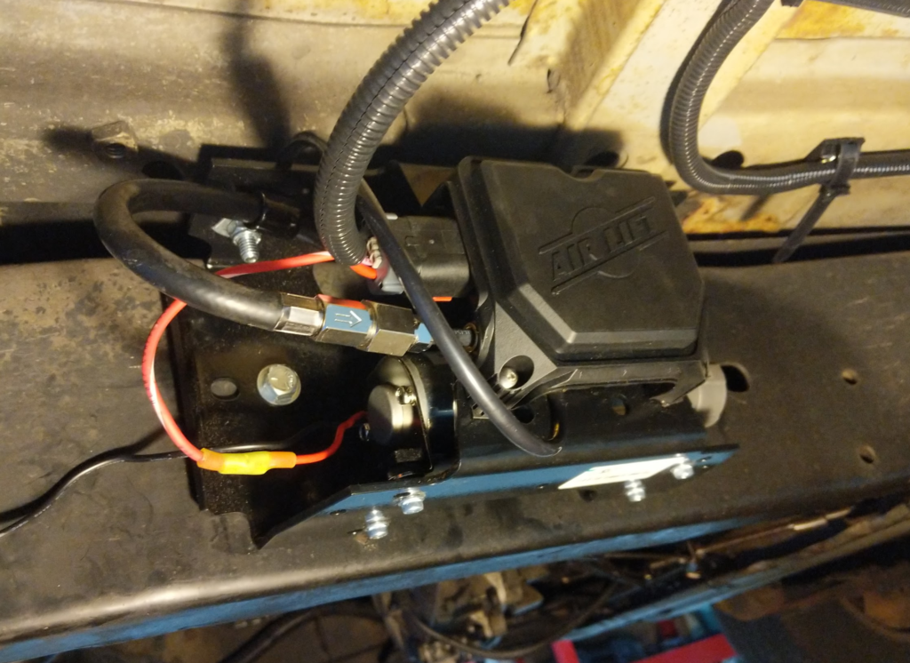
Then I mounted the AIR LIFT 25980EZ to the passenger side of the frame, about half way between the front and rear wheels.
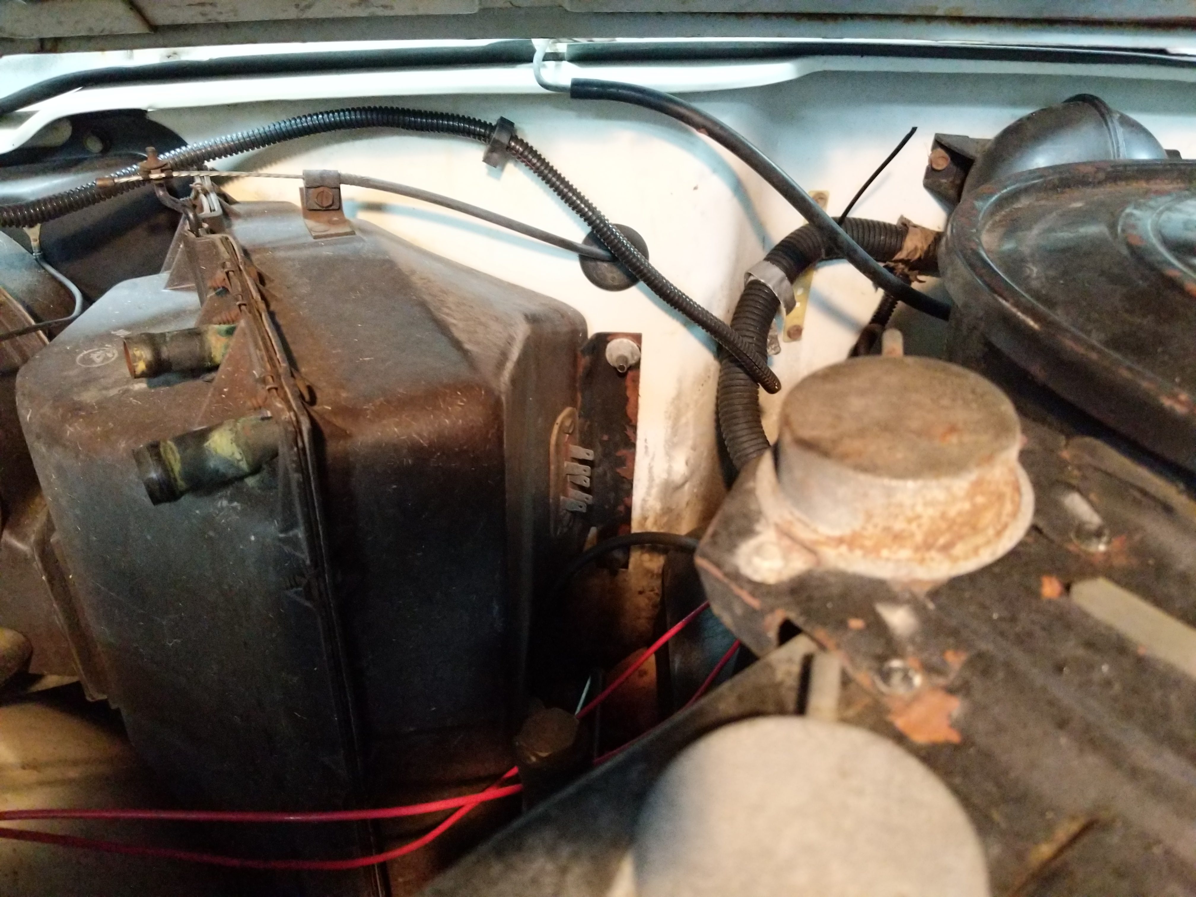
Both air bags are plumbed up with a T to the output of the air controller on it. I put the inlet filter under the hood to keep it out of water.
I have been running this for over 4 years now and I really like how it turned out. I am planning on adding a T fitting and air line hookup so I can fill/refill tires with the system. Maybe this coming up spring?
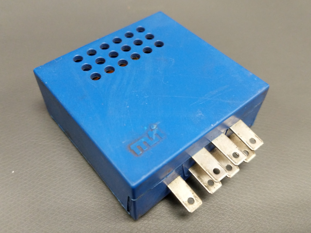
Leave your keys in the ignition? (wait cars don’t have keys anymore….) Leave your headlights on? (wait cars have automatic headlights…) Well you don’t forget when your car beeps or chimes at you! Cept my Wagoneer doesn’t!
Stuffed up under the dash is this blue box which is the chime module AMC used in lots of there vehicles.
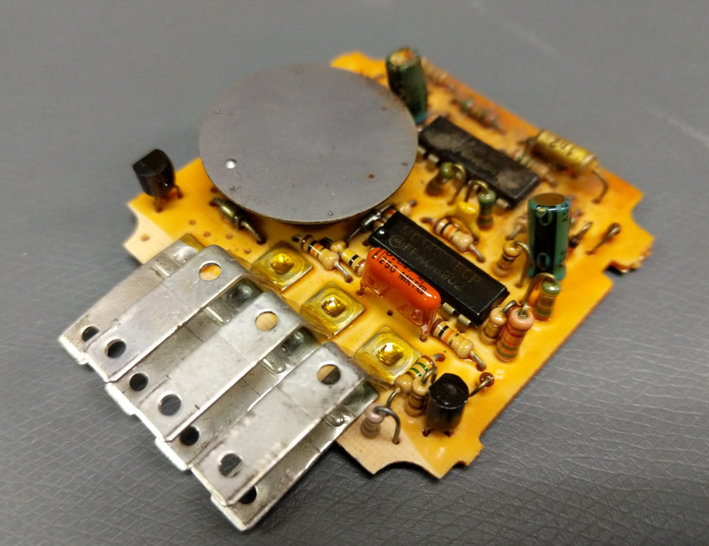
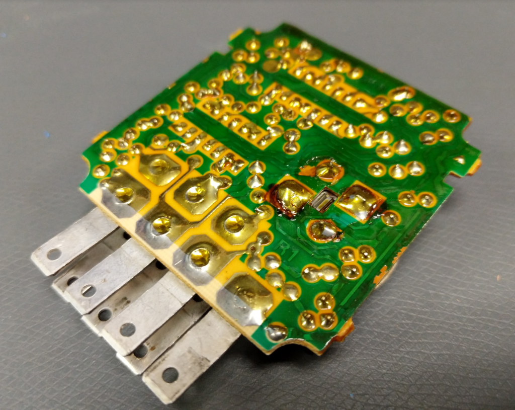
If you pop open this blue box you will get at the PCB inside.
If all the components look good and no obvious damage then either the solder has fractures or the electrolytic capacitors are bad.
The circuit uses the some of the capacitors to create a RC oscillator for the tone the metal can speaker uses.
To get mine working, I reflowed all the solder joints and added to leaded solder to the joints. Then I replaced all the electrolytic capacitors with new equivalents. The values and voltage ratings of the caps are printing on them.
The board is conformal coated but a soldering iron can “melt” right through it. I wasn’t successful at removing the coating with solvents.
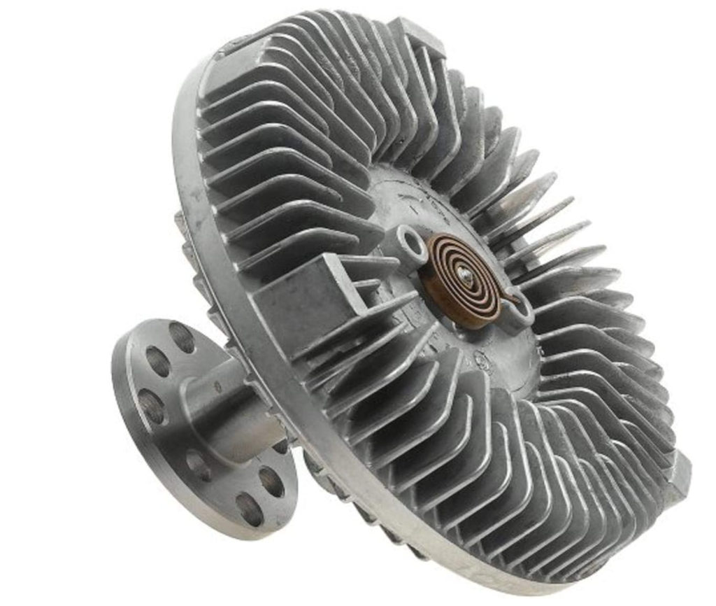
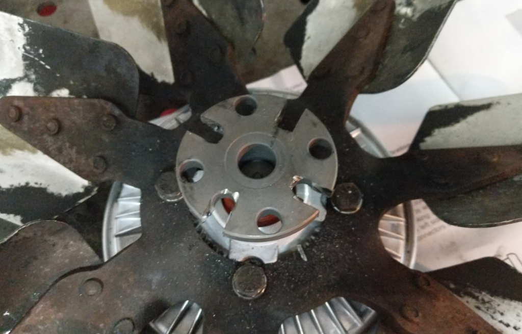
The Wagoneer’s cooling system is just barely adequate for the hot Houston summer weather. To help improve cooling I am going to upgrade the fan clutch from the normal duty part to the severe duty. The severe duty kicks in and engages the fan at a lower temperature and “slips” less. This enables the radiator fan to spin faster.
You want part number Hayden 2797.
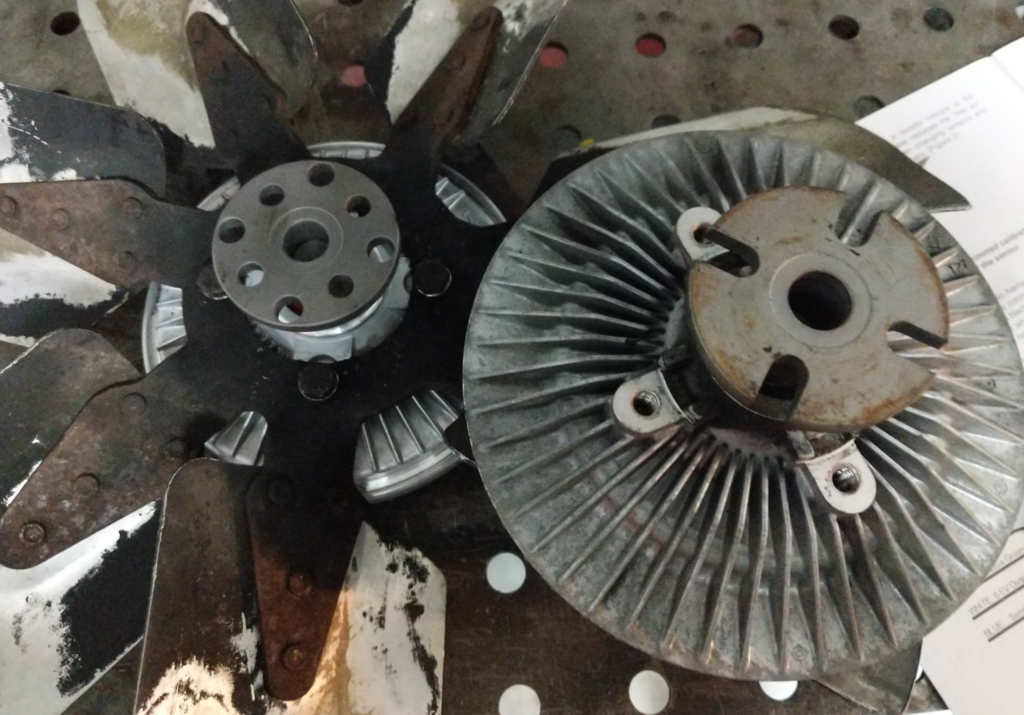
Old fan clutch on right. New Hayden 2797 already installed on the fan left.
Now the problem with the Hayden 2797 is that the bolt pattern does not exactly match what is needed on the AMC 360 water pump.
Solution? Cut out the smaller of the two bolt patterns into slots!
Not the best on job with the cut off wheel but it works.
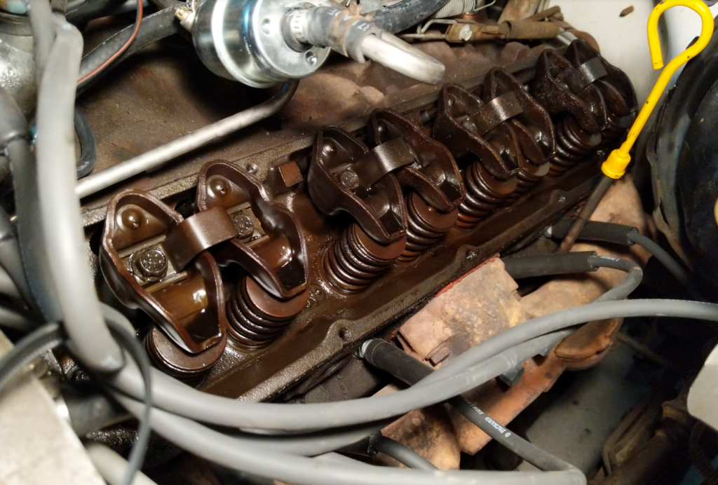
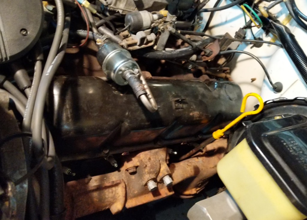
The Wagoneer’s AMC 360 engine is a bit worn out. The engine blows a bit of smoke on start up so I suspected it was the valve seals leaking down some oil into the cylinders when the engine isn’t running. The engine itself doesn’t burn much oil other wise.
The overview is: remove the valve covers, remove rockers and push rods, remove valve stem keepers and springs, install new seal.
Parts / Supplies Needed
Valve Cover Gaskets
FEL-PRO VS 50001 C
Valve Seals
EngineTech S2886
Sealant
Permatex 80062 High Tack Gasket Sealant
Tools Needed
Valve Spring Compressor
Proform 66784
Valve Holder
Lisle 19700
Air Compressor
Fittings to hook up to the valve holder
Spark Plug Socket
SAE Socket Set
First move everything out of the way of the valve covers. For me the spark plug wires and the fuel lines where in the way so I had to disconnect these and move them out of the way.
Remove the valve cover. Clean up any old valve cover gasket left on the engine and valve cover.
Remove all the spark plugs from the engine. Keep them in order if you are not replacing them.
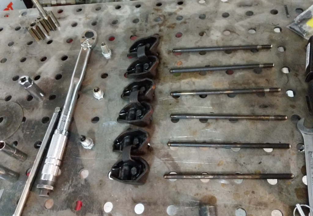
Next we want to remove all the rockers and push rods. To remove the rockers you want both valves to be closed before removing the two bolts holding each rocker pair on. Rotate the crank with a socket and wrench till the valves close (valves up and push rods down) then remove the bolts. Repeat for all 8 of the pairs.
Make sure you keep the rockers and push rods paired up and organized so that the rockers and push rods can go back to the original location when reinstalling.
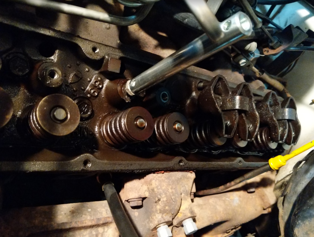
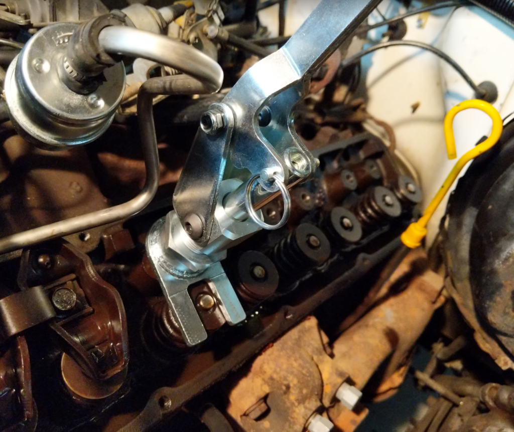
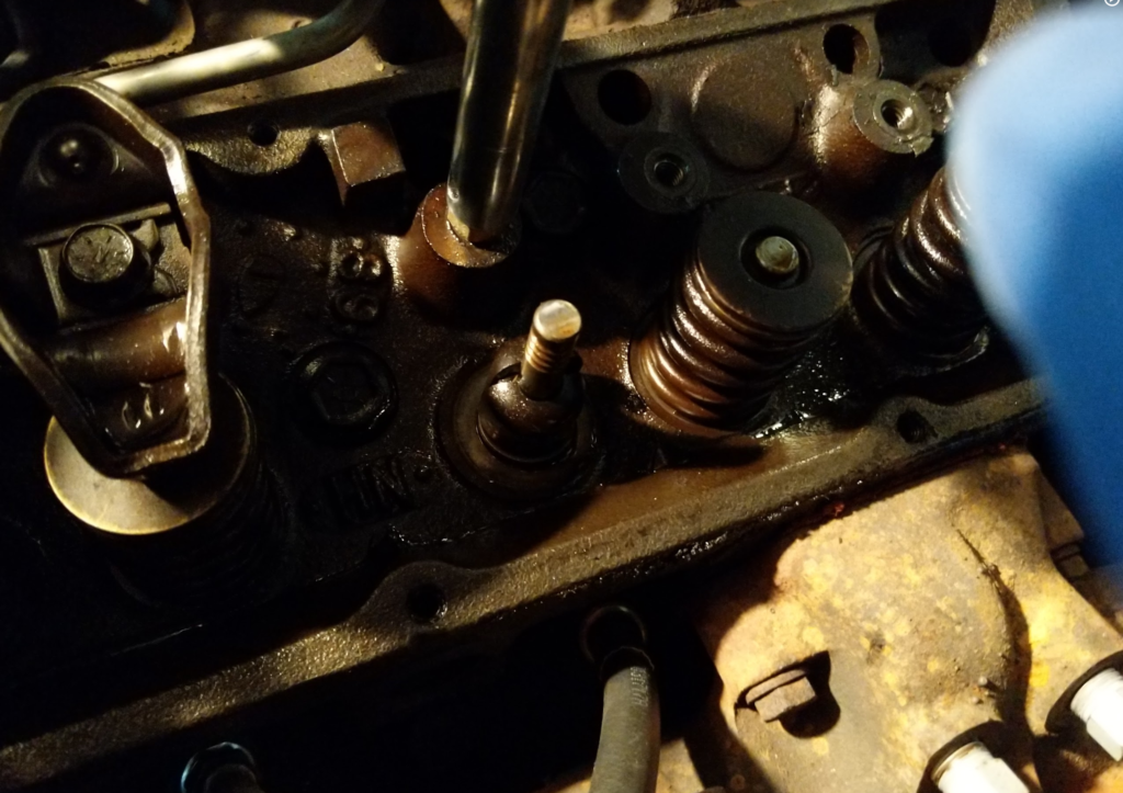
Ok next, thread in the valve holder into the spark plug hole and apply continuous air from the compressor into it. This will hold the valves up while we remove the valve keepers and springs to replace the seal.
Next, thread on the stem of the valve spring compressor tool into the rocker bolt.
Install the rest of the valve stem tool over the stem.
WHAT EVER YOU DO. DON’T PRESS DOWN ON THE VALVE STEM. JUST THE SPRING.
Pressing down on the valve stem will break the seal of the valve and then the valve will drop into the cylinder. If that happens…. Time to order head gaskets and bolts.
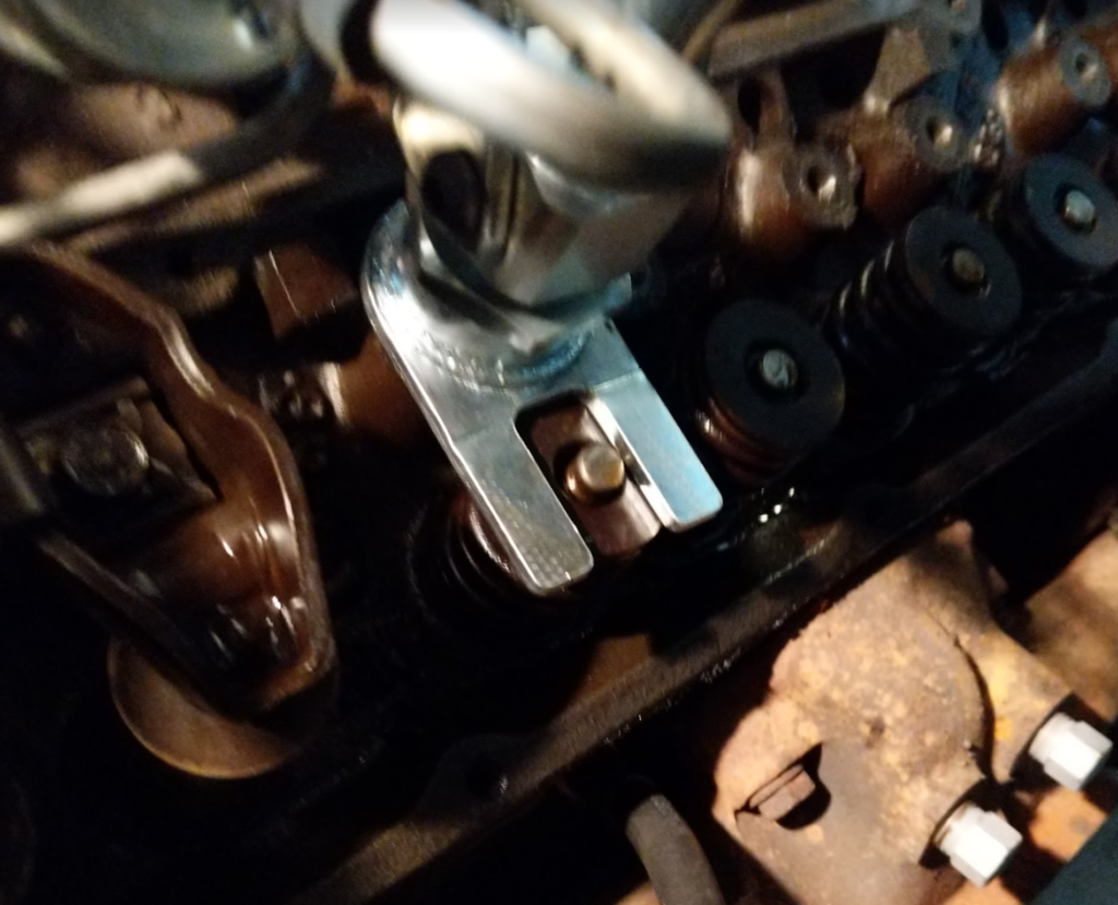
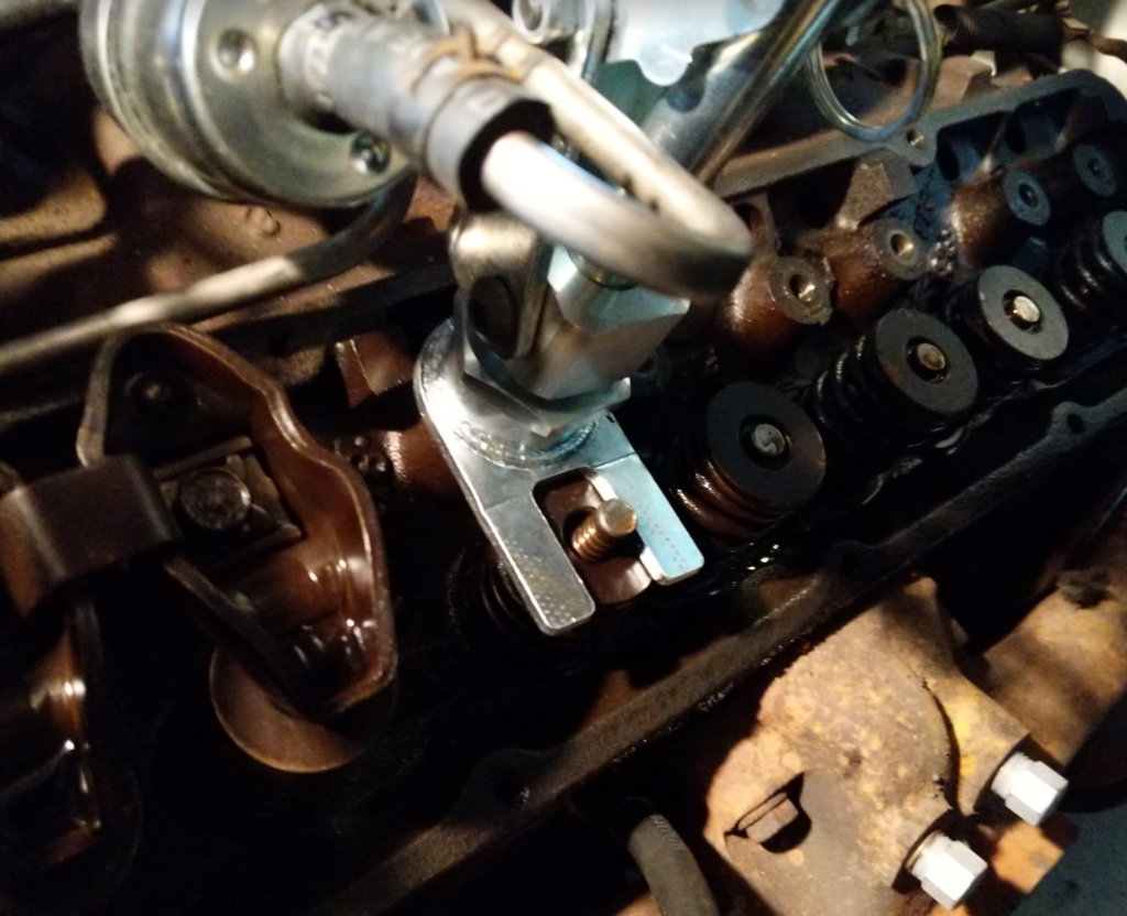
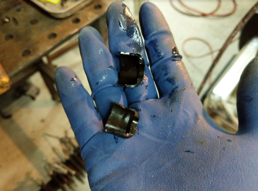
Pull on the valve compressor and it will press the top of the valve down. This will compress the spring around the valve stem. The valve keeper is two parts around the valve stem. Make sure you don’t loose them when they come loose from the valve stem.
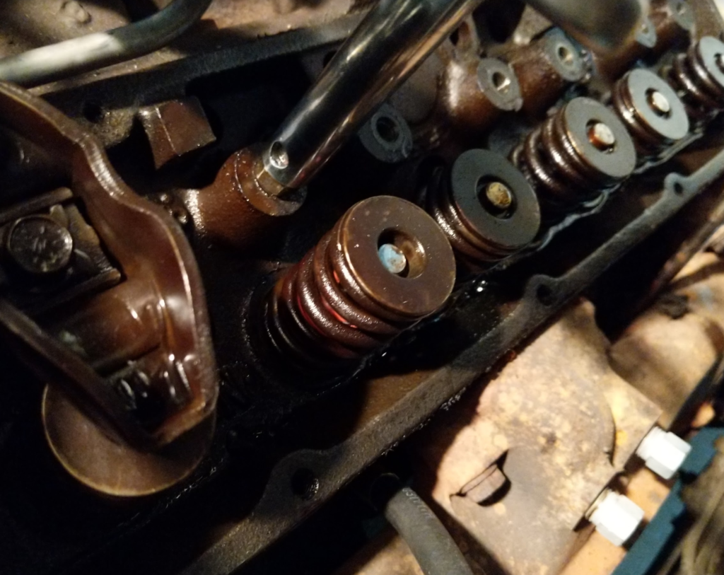
Starting compressionFully compressed with valve keepers removed
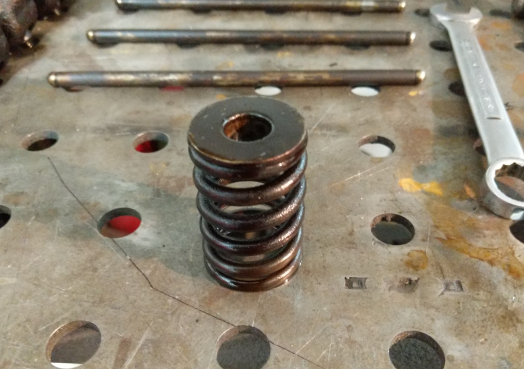
Once the valve keepers are removed, release the spring tension and remove the valve compressor tool. Then remove the valve spring.
Here, remove any of the valve seals that still exist. Mine where all cracked or missing.
I don’t know if the original valve seals where hard plastic or just the rubber hardened up over the years but all of mine where shattered.
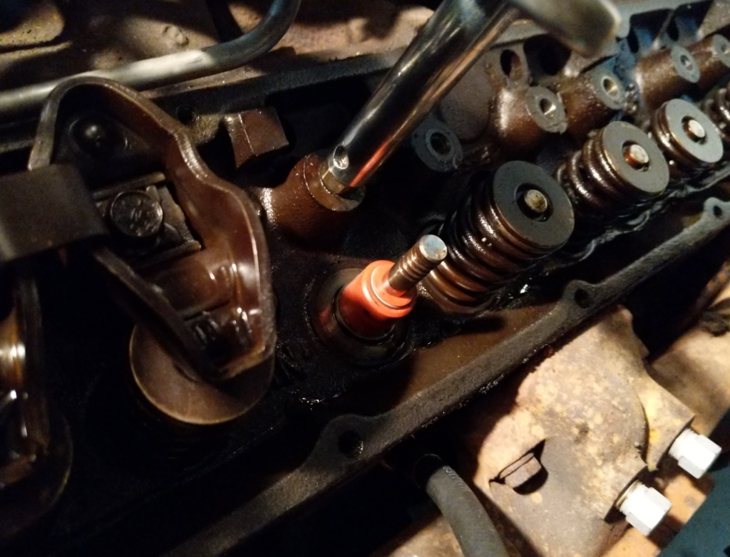
Slip on the new valve seals which are silicon with a spring to keep them in place.
Replace the valve spring.
This is the most difficult part, use the valve spring compressor to compress that spring down and then with your other hand…. handle the two pieces of the valve keeper and hold them on the valve stem. Slowly release the compressor as the valve keepers set.
Do this 15 more times.
Then reinstall the pushrods and rocker arms back to the original locations. When installing the rocker arms, you need to make sure the valves are closed, just like when removing the rockers. What I like to do is to install the pushrods and rocker arms and then screw down the rocker arm bolts till I can tell what position the valves are in. Rotate the crank till both valves are closed and then torque to spec… which is 19ft lbs.
Then replace the valve covers. I like to use a high tack sealant to hold the cork to the valve covers while installing. Valve cover bolts are torqued to 45in lbs. Remember inch pounds!
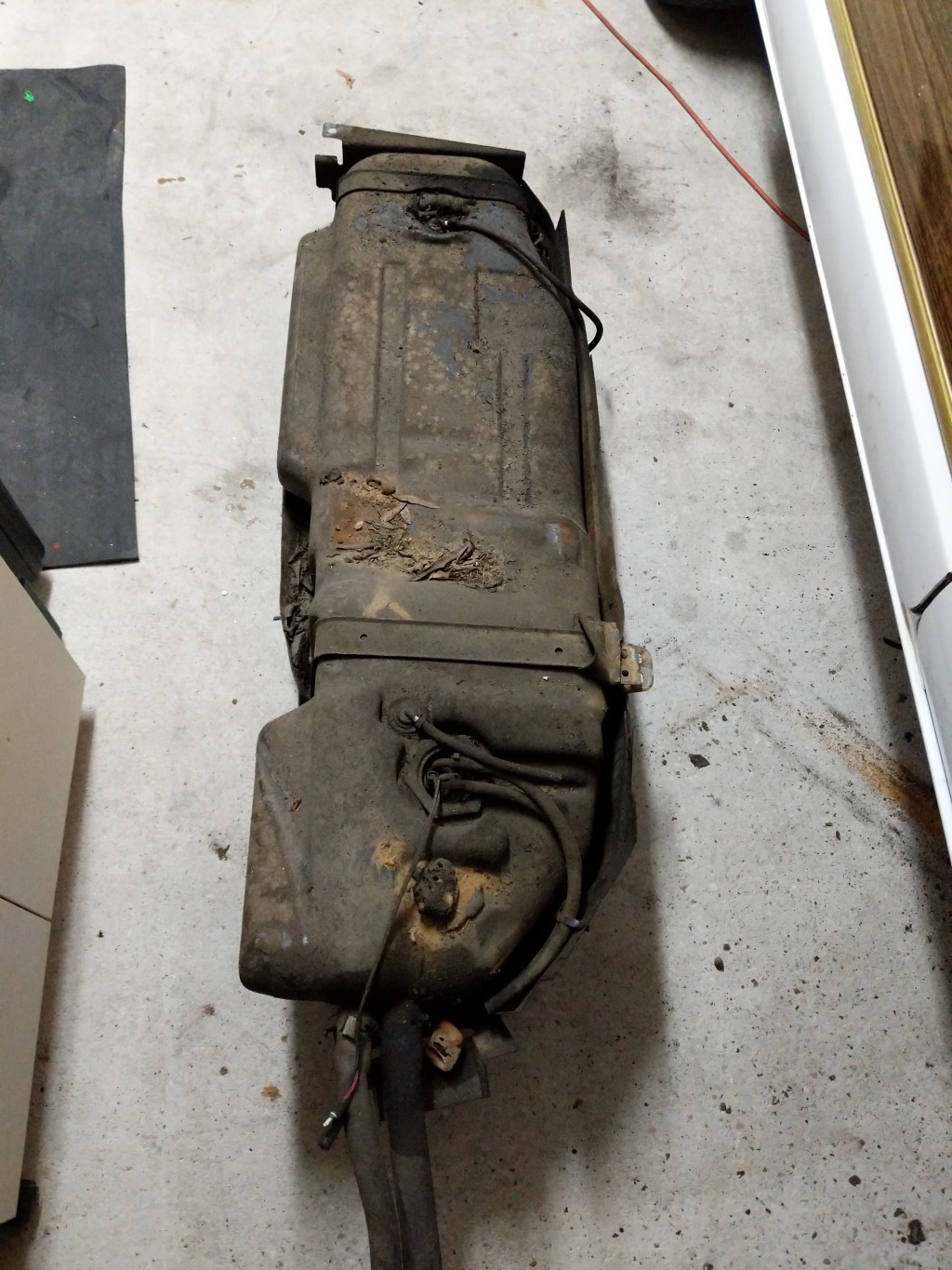
A common issue with Grand Wagoneers is rusting gas tank skids. Gas tanks on Wagoneers are plastic. To support the weight, the gas tanks are fastened to a metal skid. Then the skid is bolted to the frame. This is a great setup as the gas tank can not rust out and clog fuel filters but Jeep made the skid plates out of thin metal with poor rust prevention so they do not last.
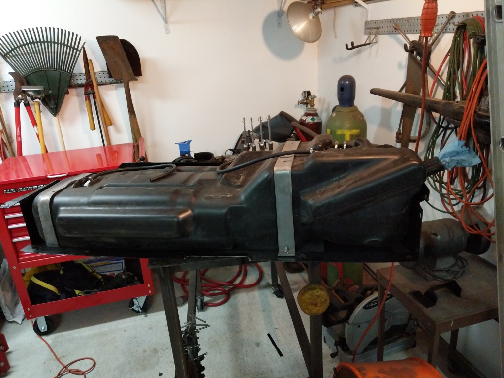
Pulled gas tank out of the wagon. Dirty!
I disconnected the fuel lines and fill lines then dropped the tank. Skid is full of dirt and rust. The straps that hold the tank to the skid where rusted through so removing the tank from the skid was easy.
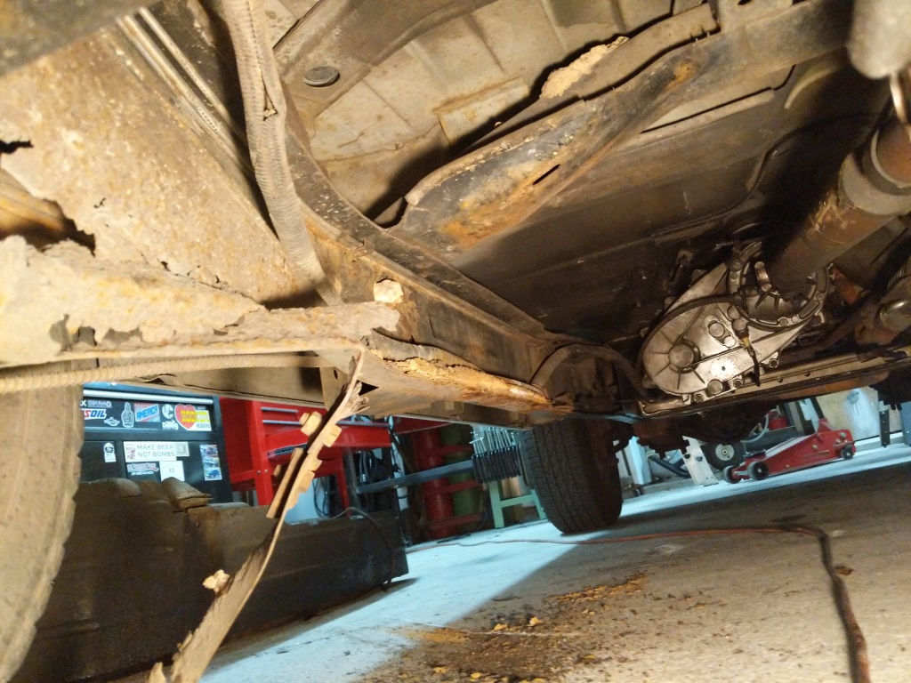
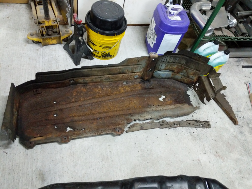
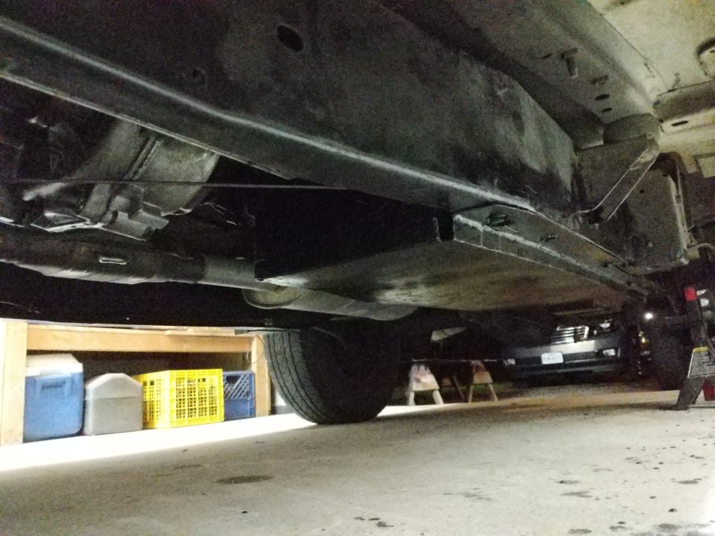
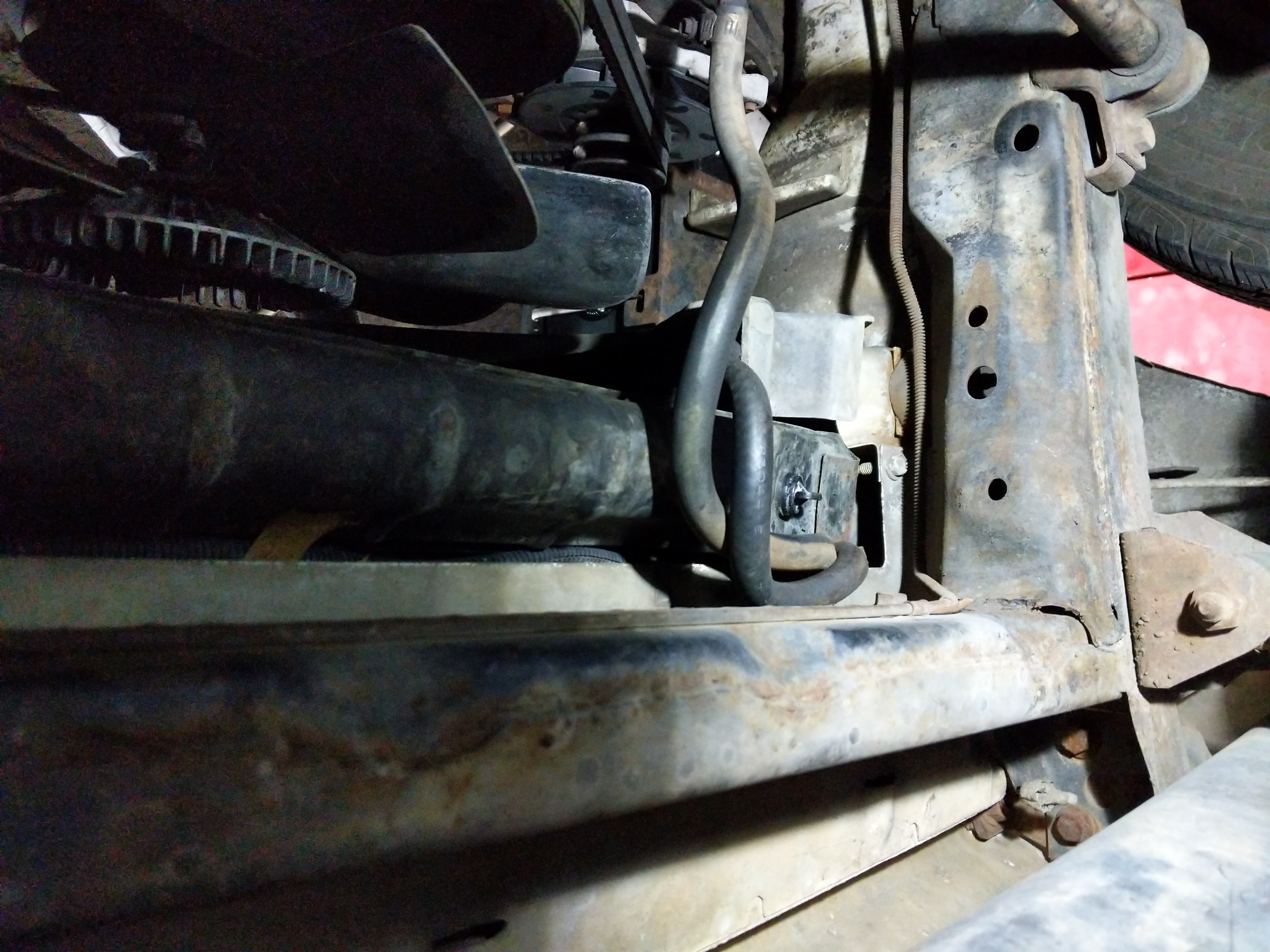
Frame inspection and cleanup.
I then inspected the frame where the gas tank lives. This is also a very common area for rust to happen. This looks bad but the frame was 100% intact. There was ton of dirt build up on the frame that at first looked like rust. The rusted holes in the left side of the picture is left over parts of the skid plate that was still attached to the frame. I cleaned up the frame and painted it with some chassis saver to prevent any further rust.
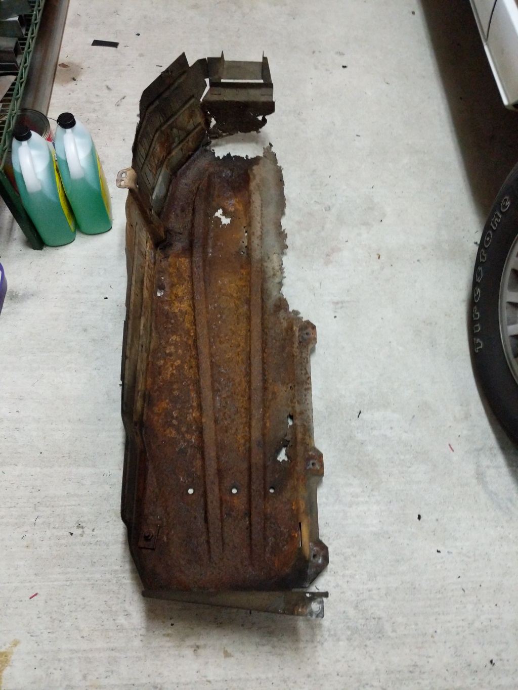
Skid plate cleaned up after removal of gas tank.
Then I cleaned up what was left of the skid plate. I was hoping to repair the skid by patching it but the skid was to far gone at this point.
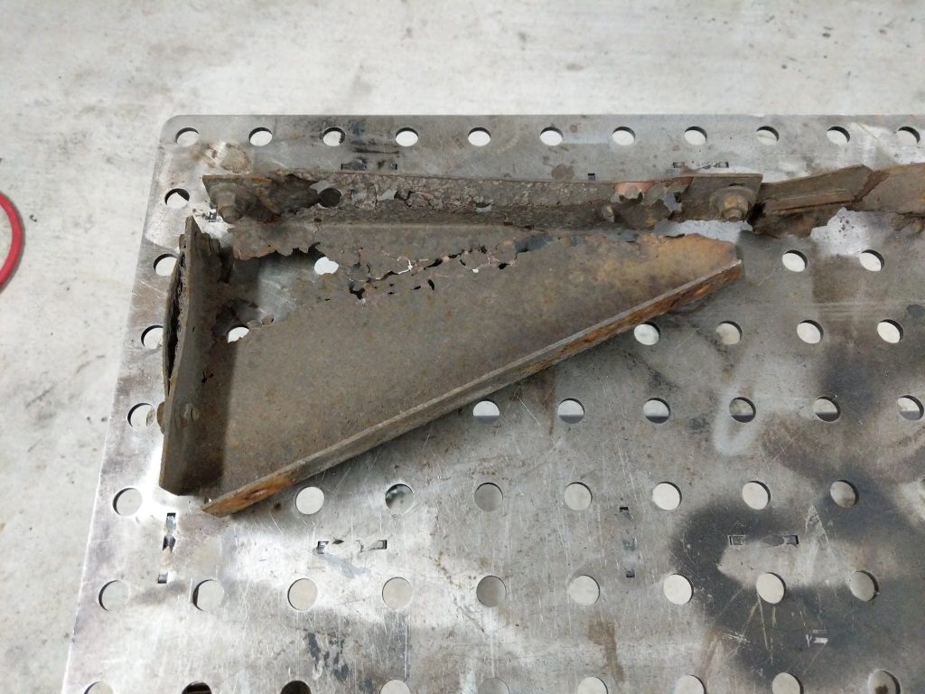
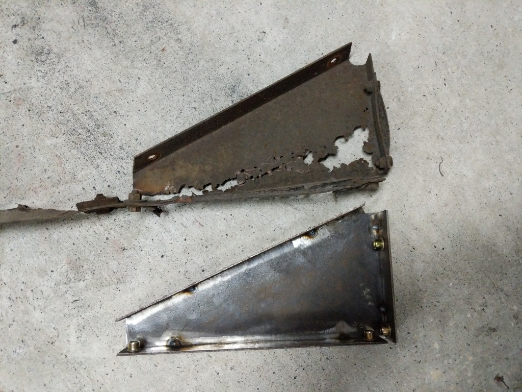
Skid plate triangle brace. Not much left of it!
Then pulled the skid plate triangle brace and cleaned it up. Swiss cheese steel. I decided to rebuild the triangle brace first since it will be easier.
Brackets for the triangle brace.
Built the new bracket parts for the triangle brace. I added nutserts to make install easier later.
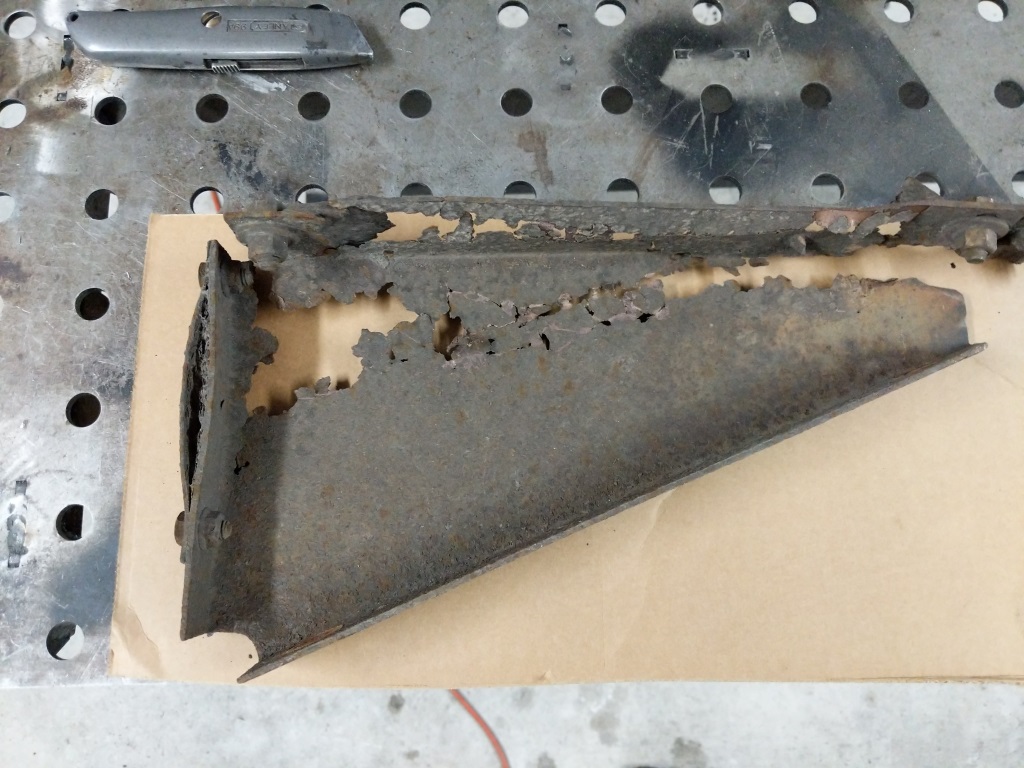
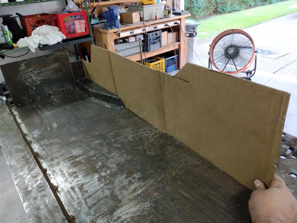
Tracing the old brace into cardboard.
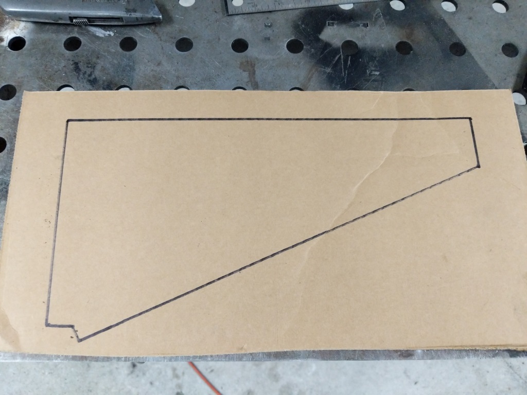
Brace traced.
Cardboard cutout.
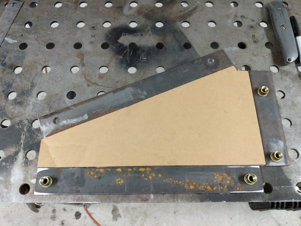
Testing fitting the brackets and cardboard cutout.
To make the rest of the triangle brace, I traced it onto some cardboard. Then I cut out the cardboard and mocked it up with the braces I cut out steel.
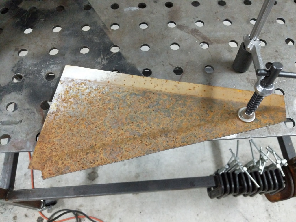
Cardboard template transferred into steel.
Steel cleaned of rust and scale.
Then I copied the cardboard into some 14AWG steel. The steel was bought LTP (Less Then Prime) which means it is rusted but it was inexpensive. Cut the steel out and then cleaned up with a flappy disc on the grinder.
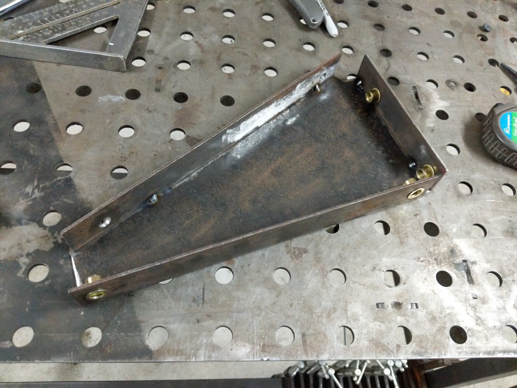
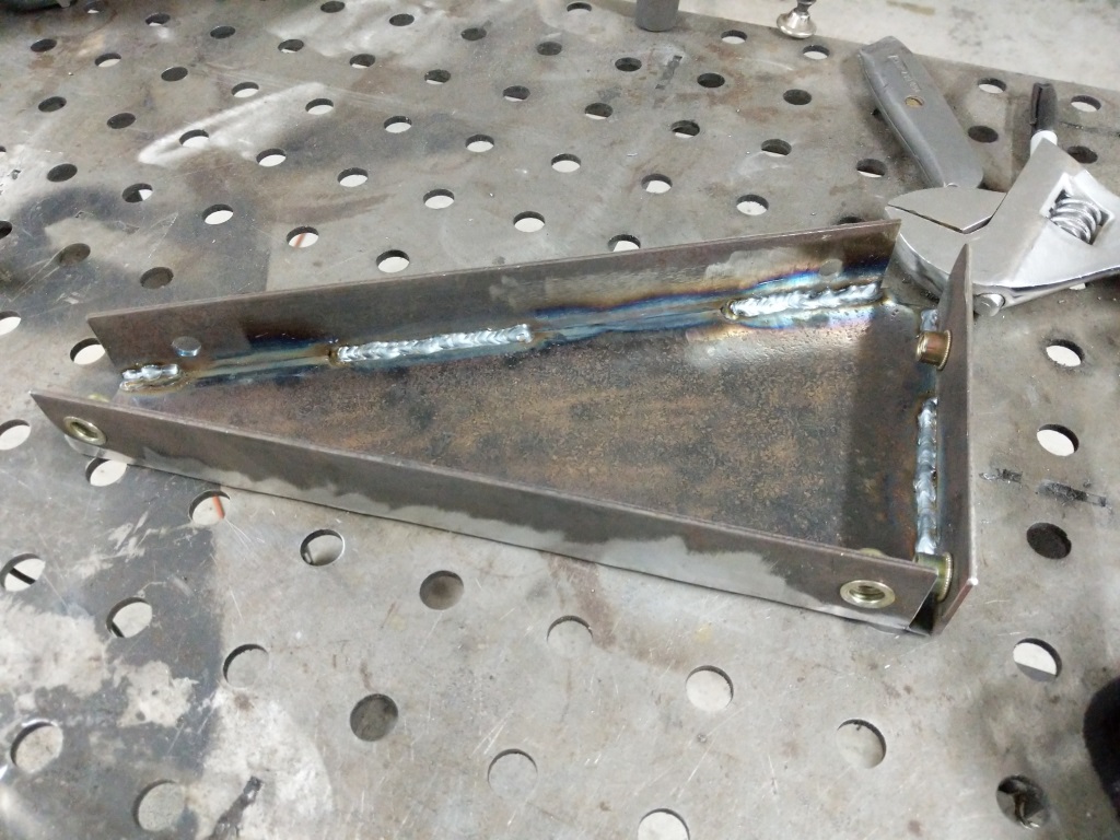
Brackets tacked to the steel triangle.
Comparing the original rusted bracket to the new one.
I then tacked the brackets onto the steel and compared it to the original bracket. Looks good to me!
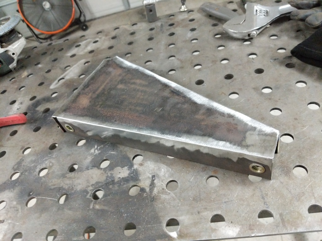
Outside welded and grinded smooth.
Inside welded. New bracket complete!
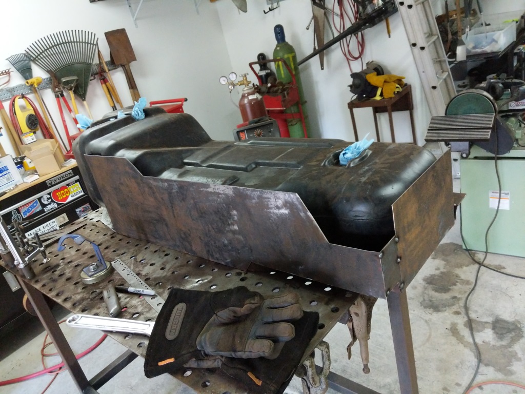
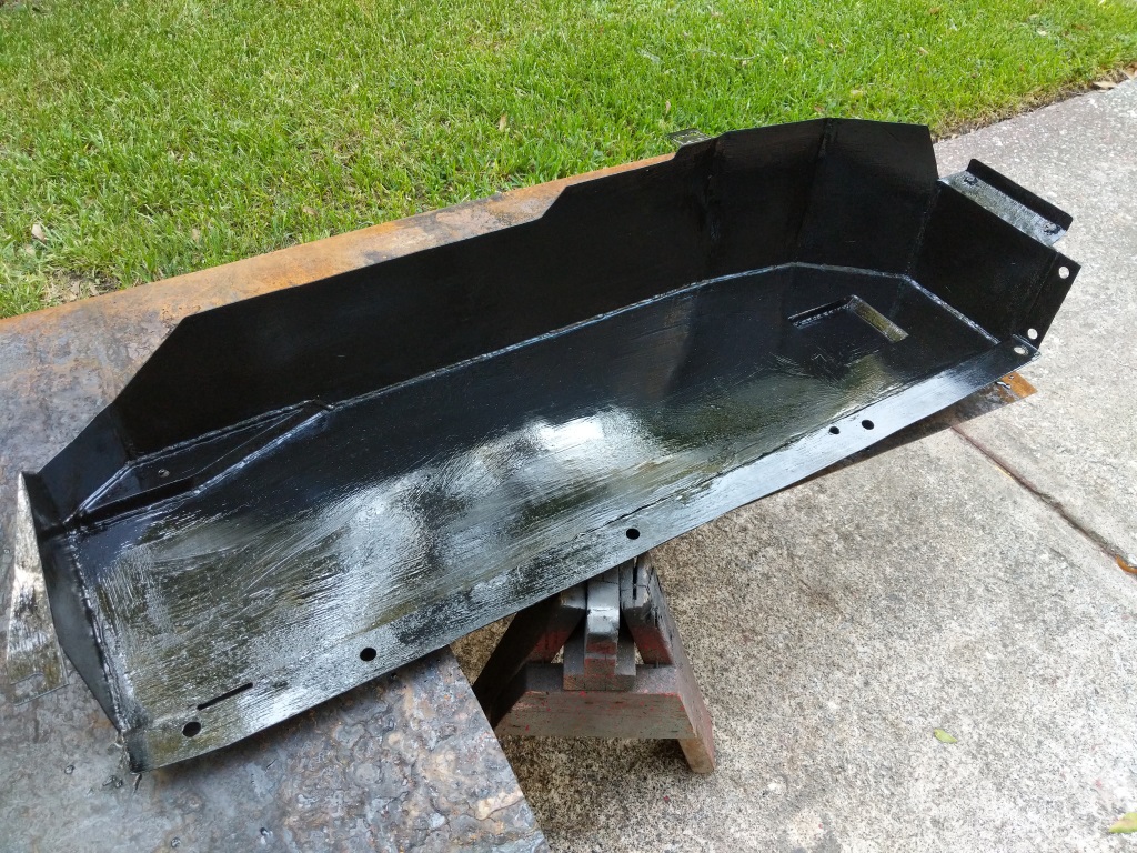
Triangle brace is complete. Time to start fabricating the skid plate for the gas tank.
Skid plate pieced back together for measurements.
I started measuring the skid plate and started cutting some steel.
Skid plate construction. Checking fitment.
This is my construction technique. Measure, make cardboard cut out, test fit, cut out of steel, and tack up.
More test fitment after making the large side panel.
Other side of the large panel.
Rest of the side panels cut out and tacked up.
The gas tank has a lower bulge for the gas pickup. Made a drop down section and fitted up some steel to cap it.
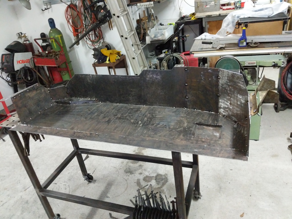
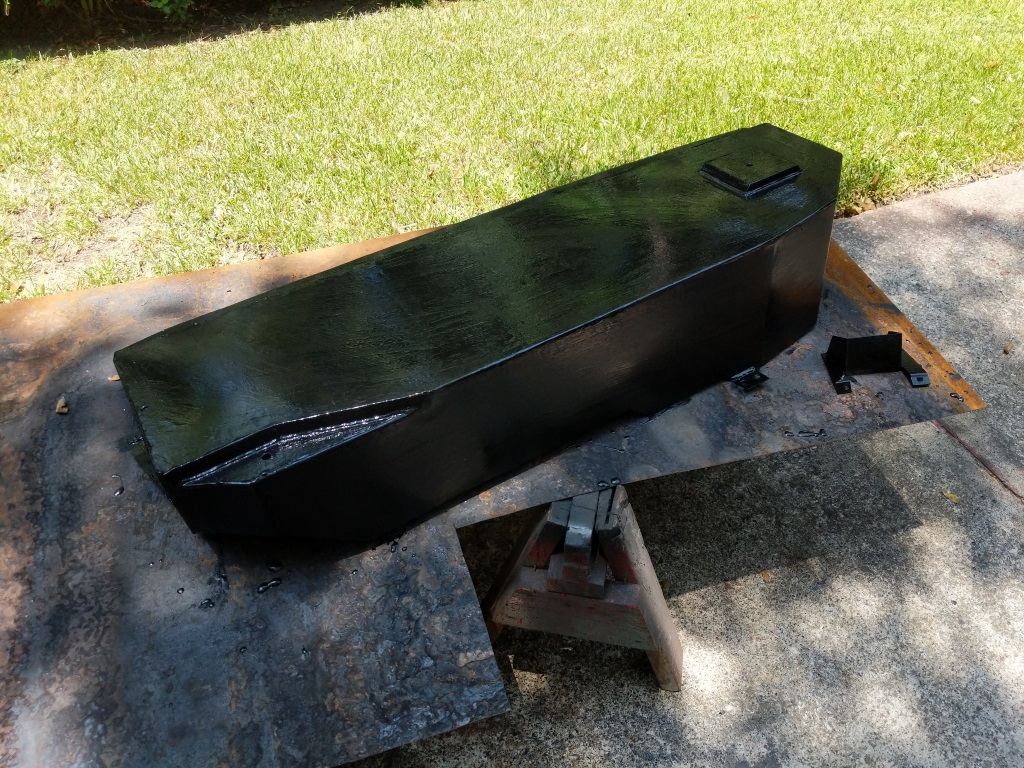
Skid plate seam welded and grinded. Lots of metal dust. My respirator was completely black after this. Wear your PPE people.
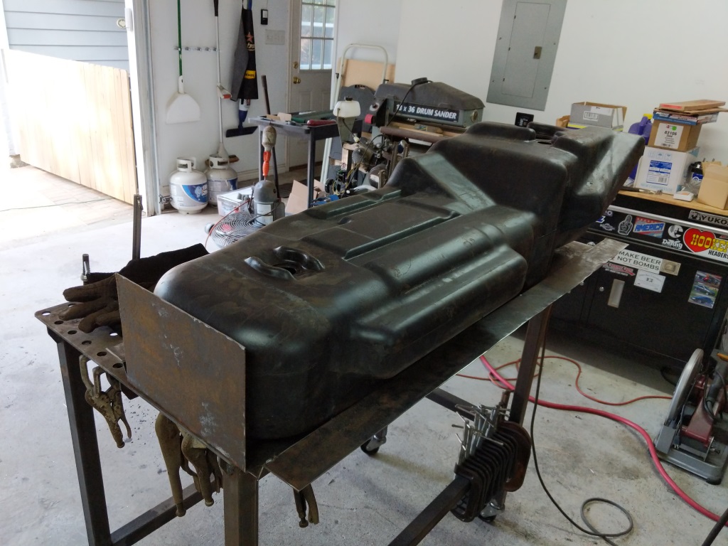
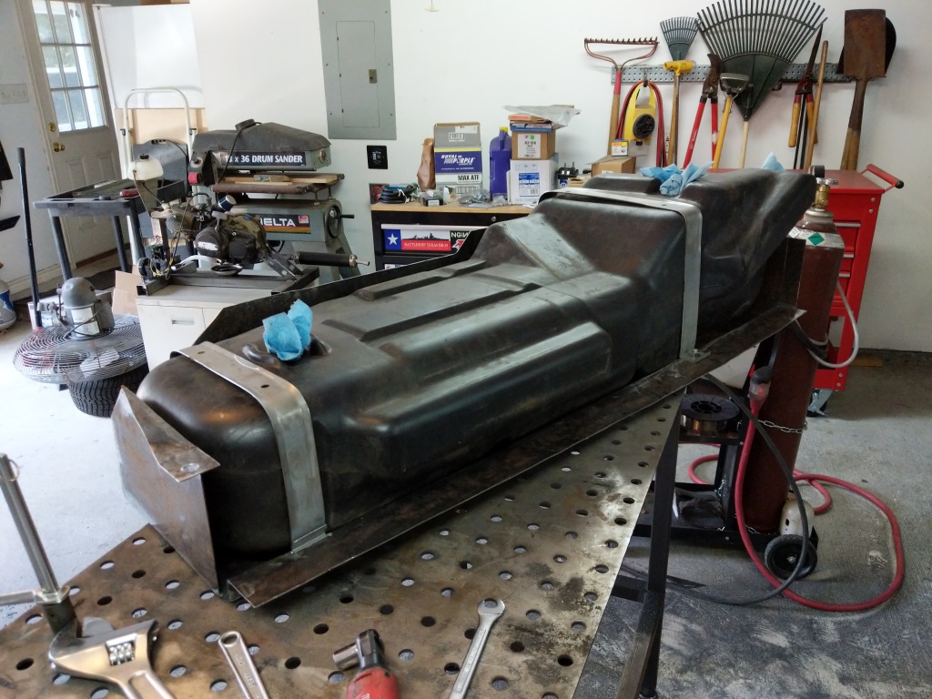
Test fitting the tank with the gas tank straps.
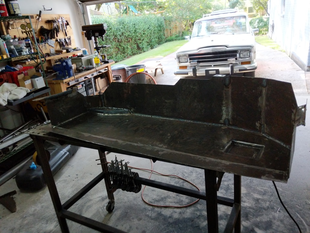
Painted the triangle bracket, skid, and associated brackets in chassis saver to prevent rust.
Bottom side painted. I drilled holes in the skid for water drainage as you can see here.
Gas tank fitted, vent lines plumbed, and fuel sender installed.
With the skid plate and triangle bracket fabricated and painted I installed the gas tank. Before that I cleaned out the gas tank with a pressure washer and dried it out. Then the gas tank received new gas tank straps, vents, vent hoses, and sending unit.
Gas tank with new skid installed under the wagon!
I then installed the skid under the wagon. Fit great and now I do not have to worry about the gas tank falling out.
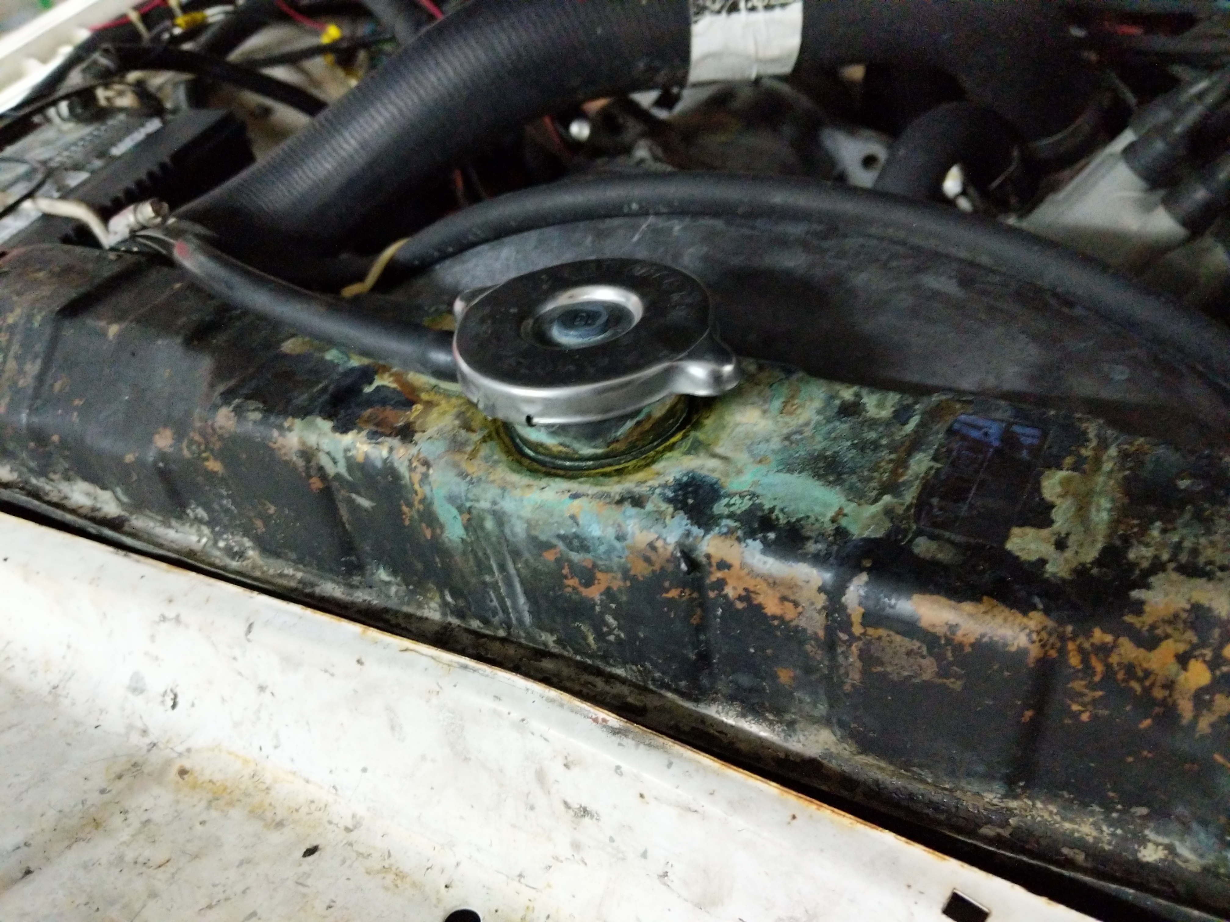
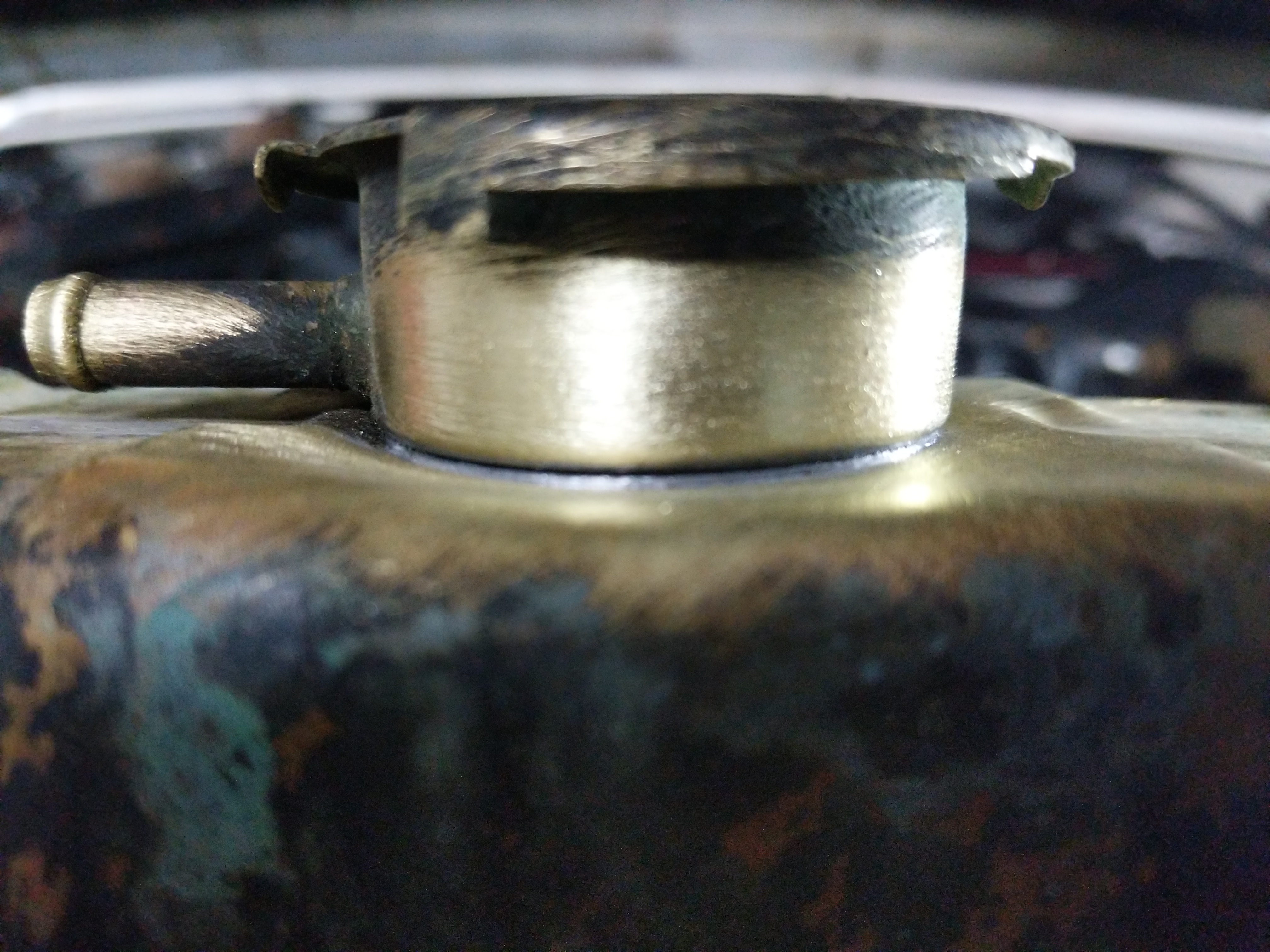
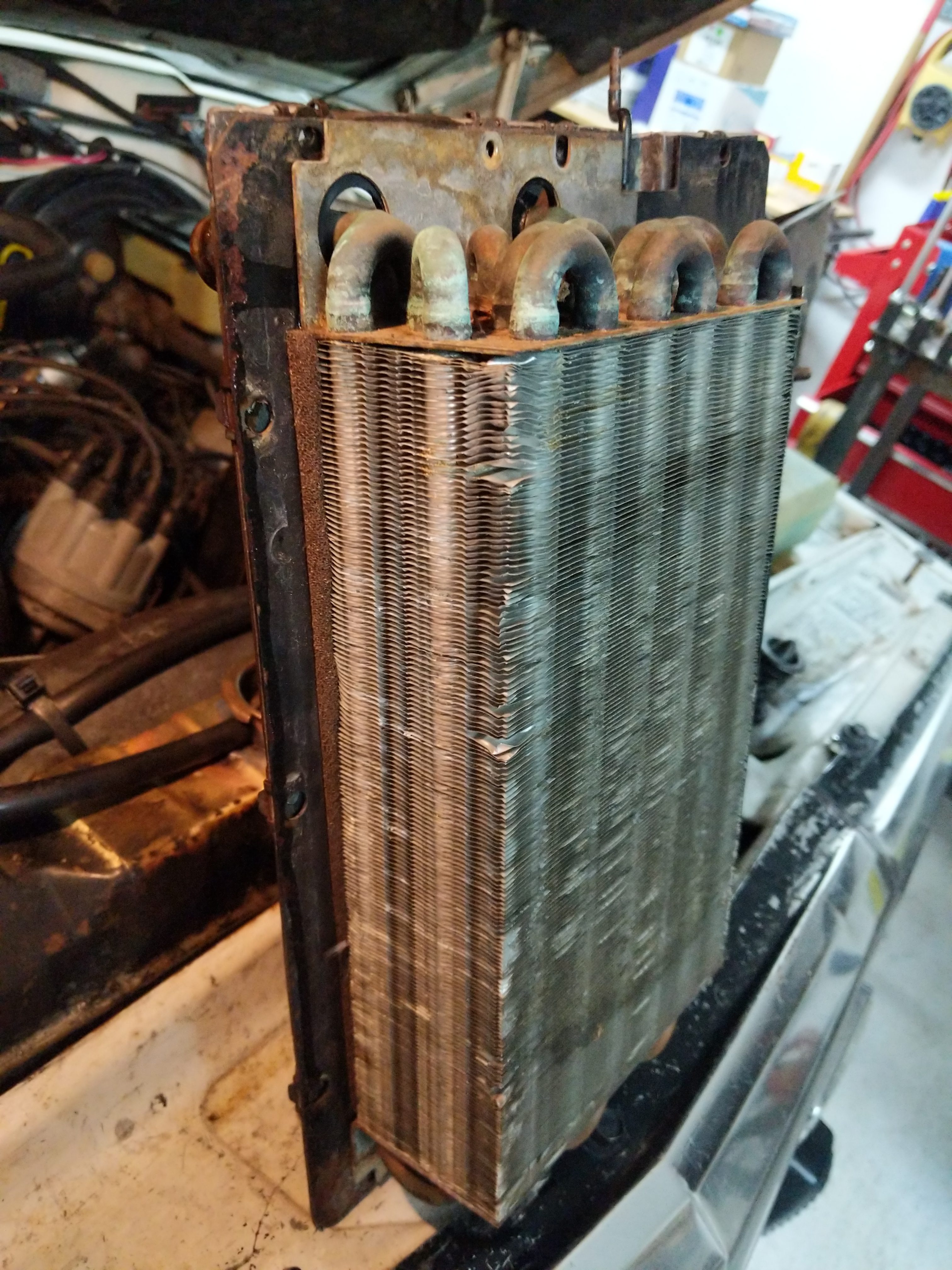
Time to start fixing things on the Wagoneer. It drives around town fine but when the engine is turned off after driving it tends to puke radiator fluid everywhere. Looking at the radiator it is clear this happens around the filler neck. Wiggling the filler neck it looks like there is a crack at the base. Since this is a brass/copper constructed radiator I should be able to braze/solder this back together.
Radiator filler neck with lots of radiator fluid (glycol) crusted around it.
While I am in here I am going to also replace the T-Stat, water pump, and clean up the heater box. Basically a cooling system rebuild.
Radiator peacock. I zip tied the transmission lines out of the way so the coolant can flow without hitting anything.
Draining all the coolant. On the Wagoneer the drain peacock is at the bottom which is nice. On the TJ Jeep it is horizontal and tends to shoot coolant all over the steering suspension. Only thing in the way was the two transmission fluid lines which I was able to zip tie out of the way.
Fluid drained.
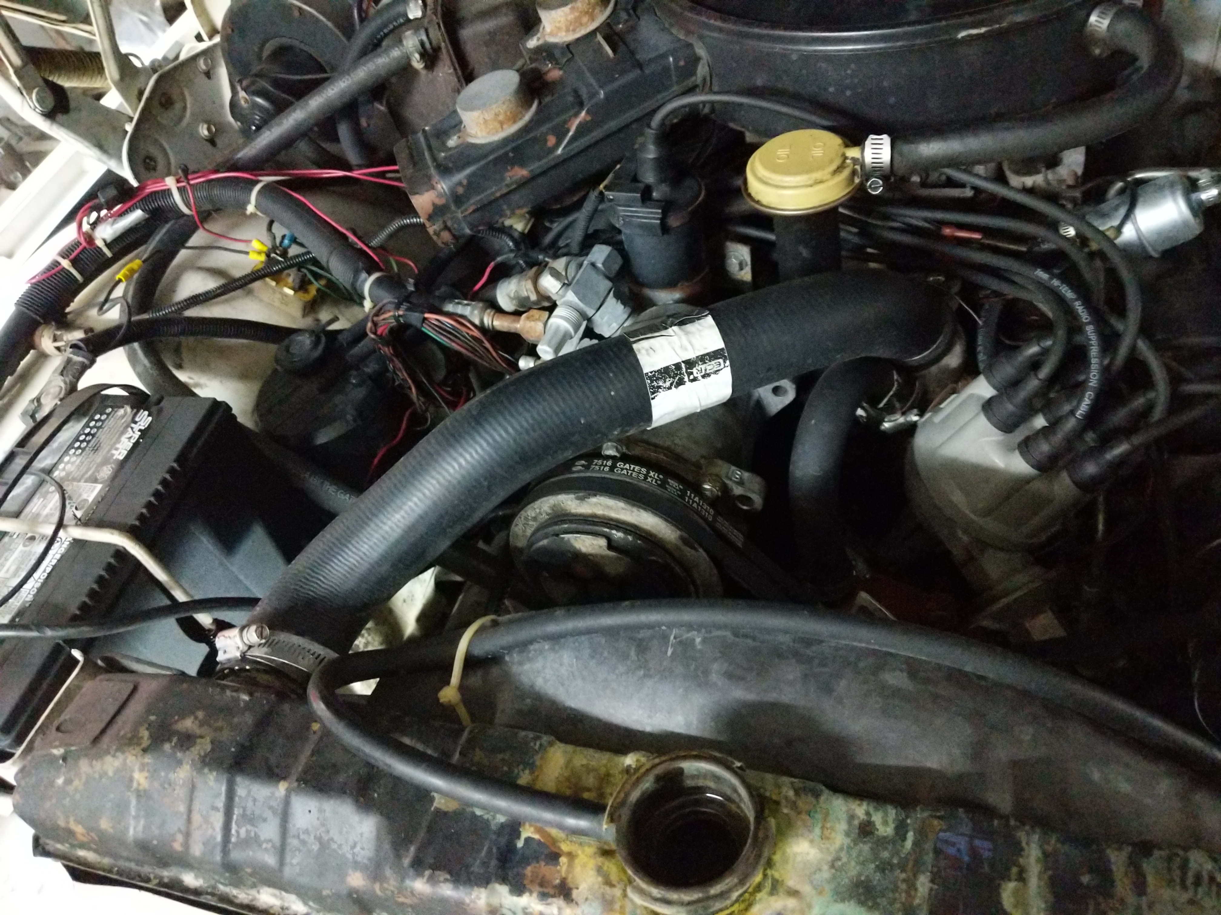
With the fluid drained I removed all the hoses in the system. There are three that attach to the radiator; Upper radiator hose, Lower radiator hose, and the hose that goes to the overflow bottle. I inspected these as I removed them and they looked to be a in shape and I will be reusing them.
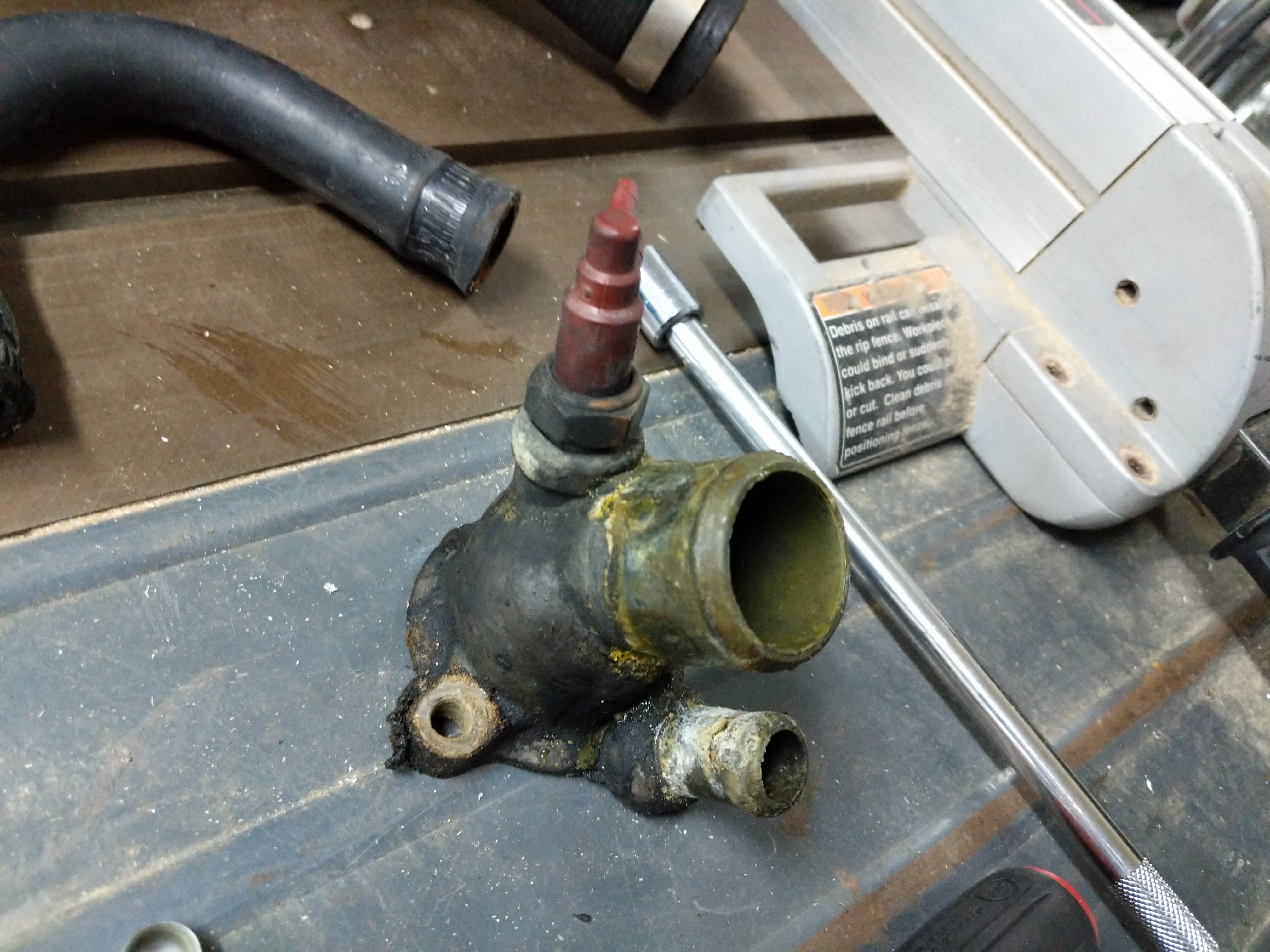
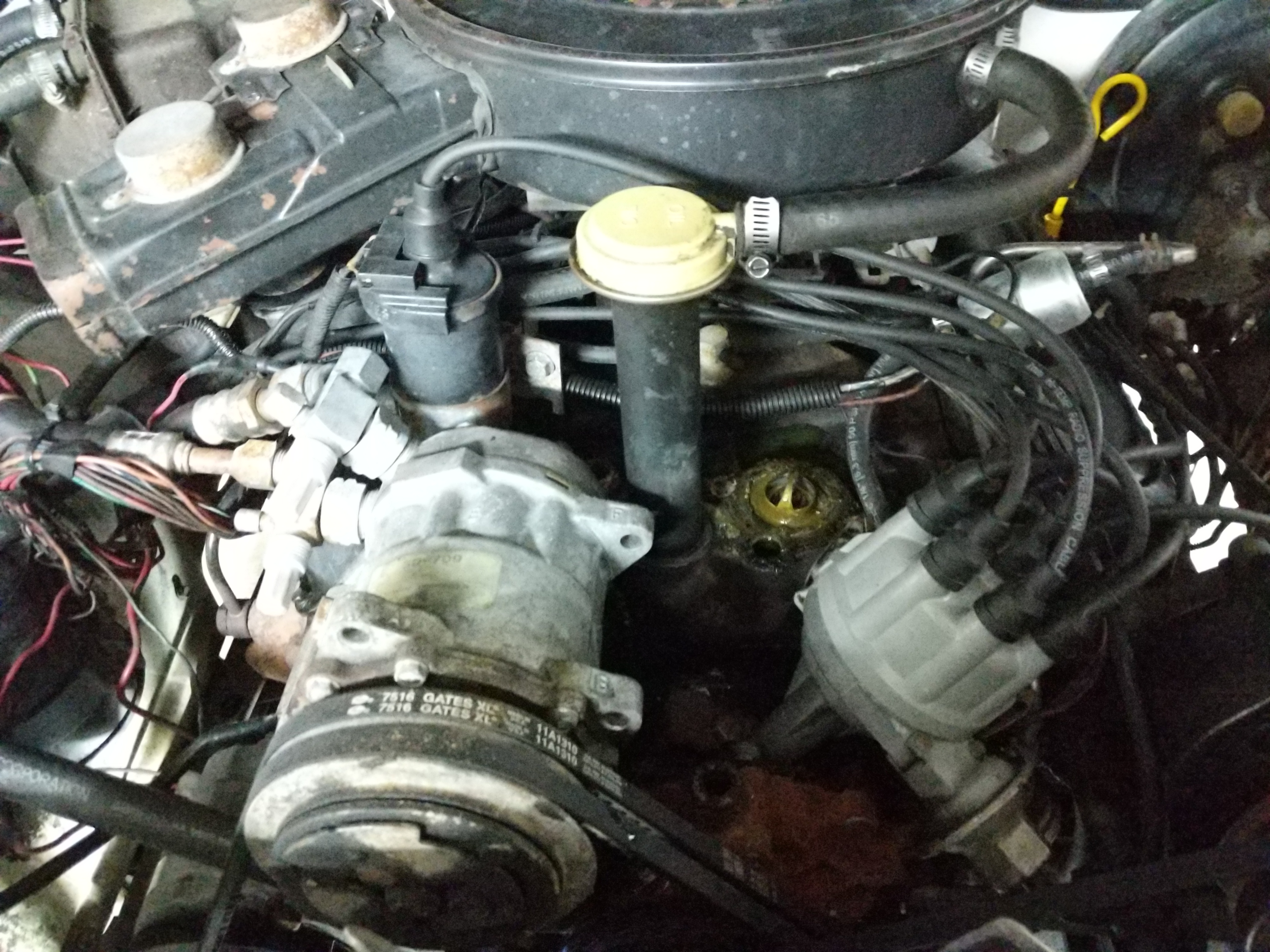
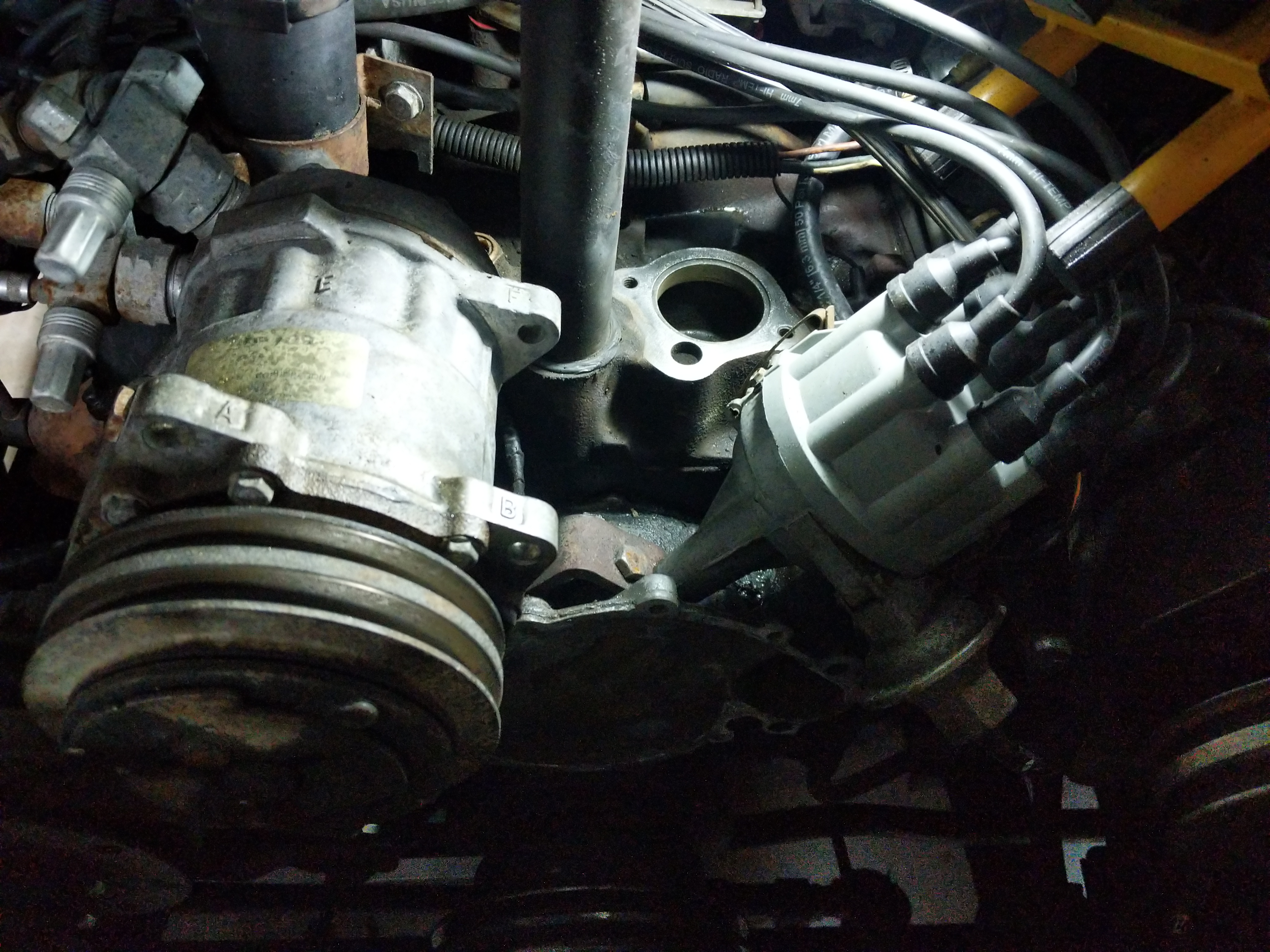
Pulled T-stat housing.
I pulled the T-stat housing and it looks like it belongs on the Titanic. I will clean this up with a brass wire wheel on the drill before reinstalling.
T-stat is installed upwards. Lots of gunk on the T-stat as well.
The T-stat itself sits in a grove on the block and the gasket is put over it. The previous mechanic just gooped RTV all over it and was a pain to remove.
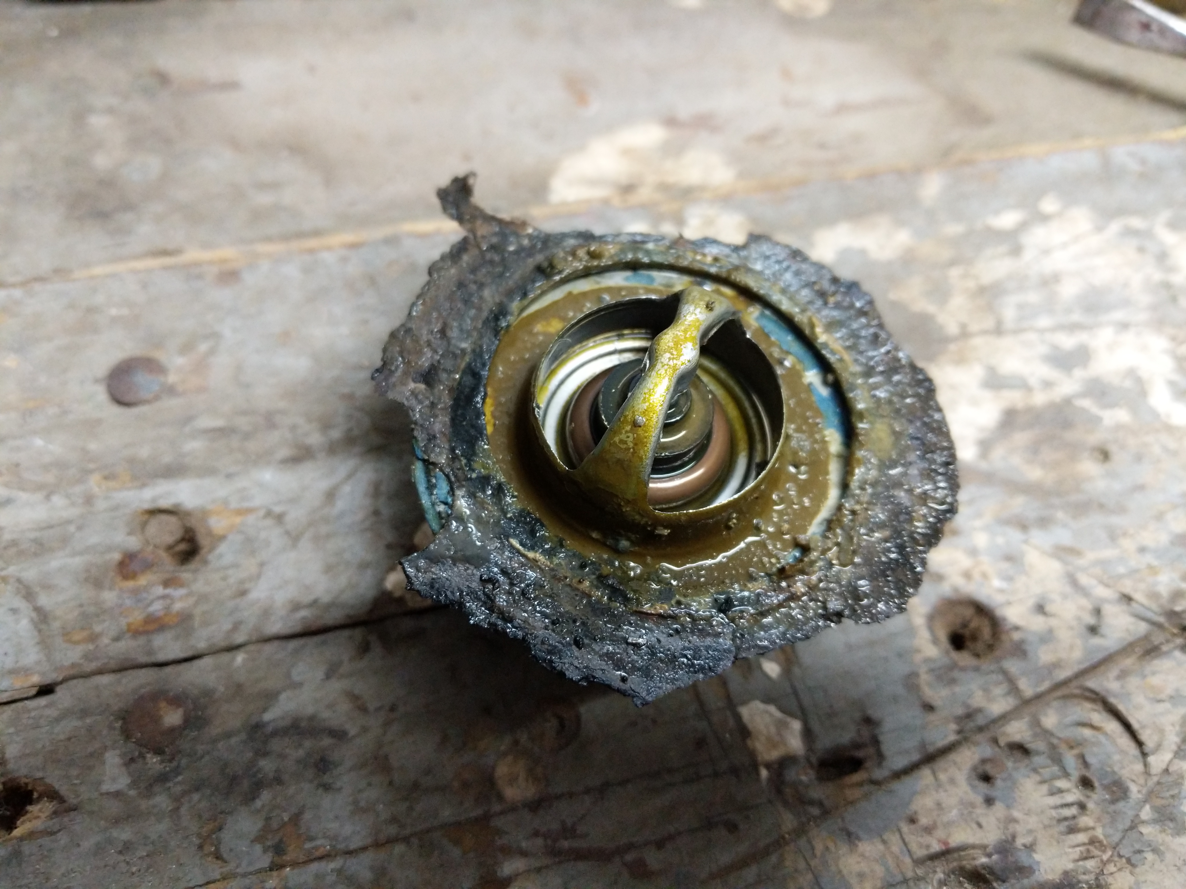
Close up of the T-stat. Nasty.
Not much left of the original gasket. Lots of rusty sludge build up on it as well. Makes sense that the Wagoneer sat for years before I got it.
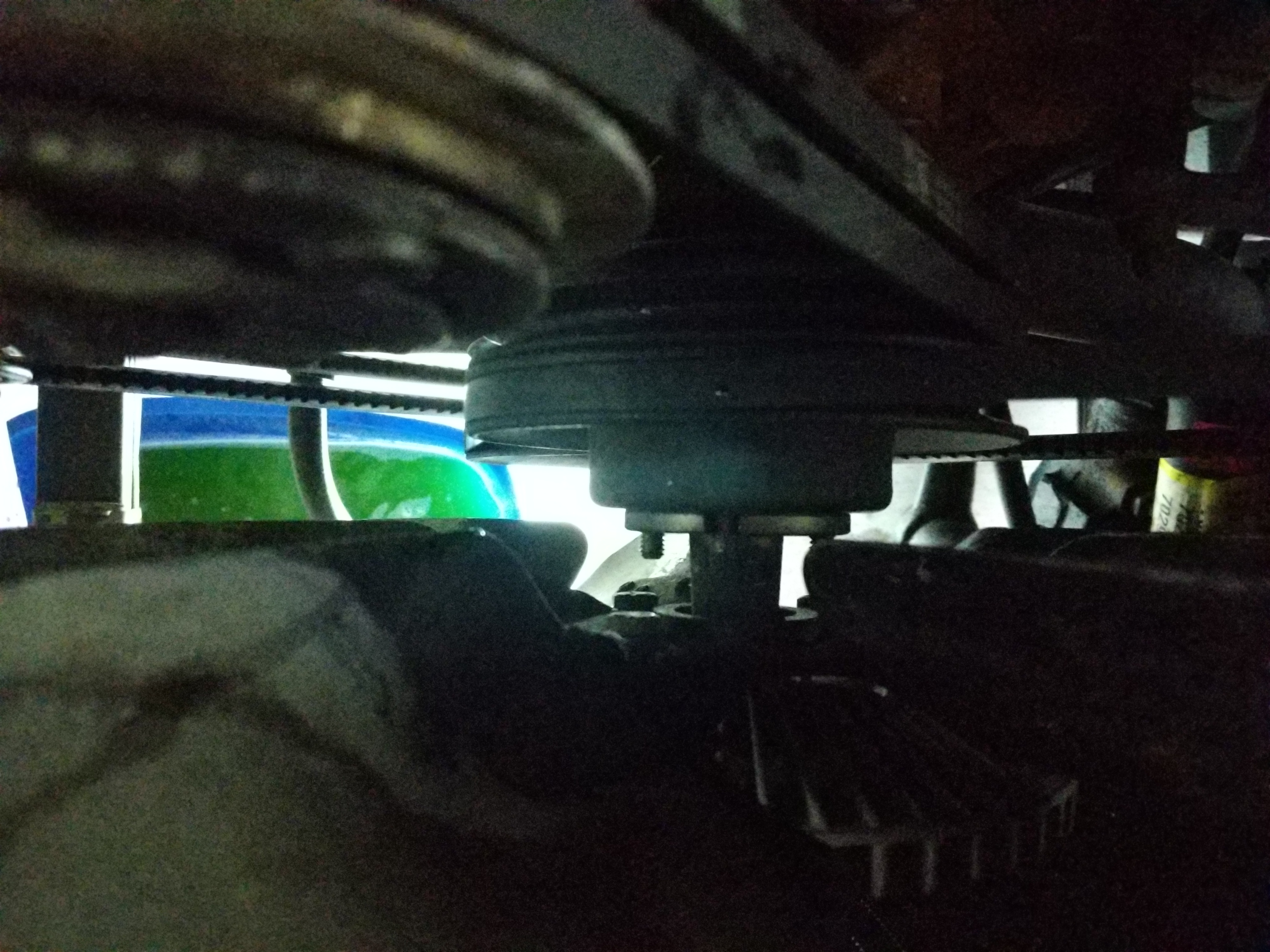
Removing the fan and fan clutch.
At this point it makes sense to make more room to work by removing the fan clutch. Since the belts are still installed it makes it easy to remove the 4 bolts on that hold the fan clutch to the water pump.
Nut/Bolt that adjusts the tension on the power steering pump belt.
Nut/Bolt that adjusts the tension on the alternator belts.
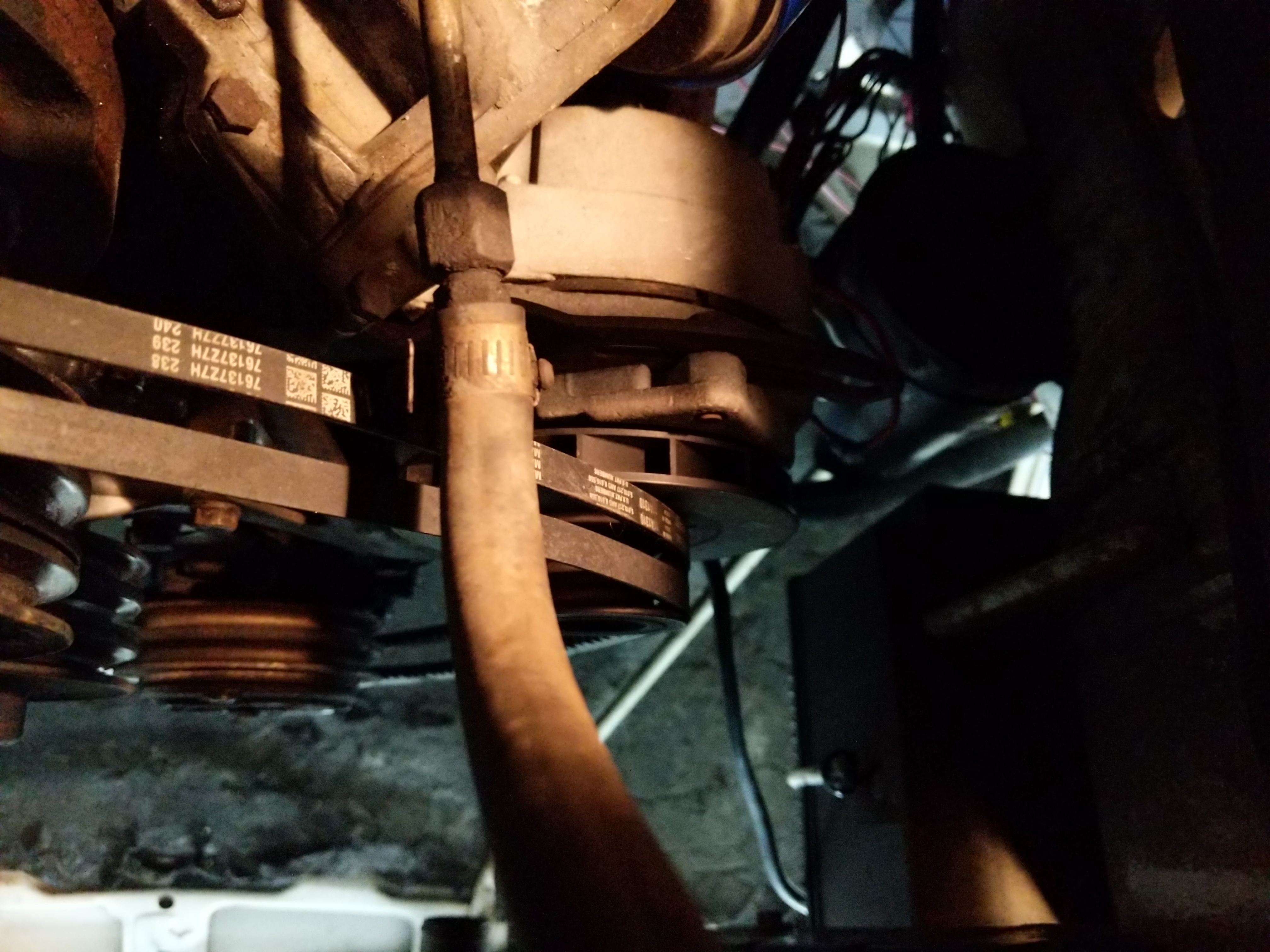
Next I removed the belts. There is a nut on the bottom of the alternator that will need to be loosened. Doing so allows the alternator to swing inwards loosening the belt. A nut on the back of the power steering pump does the same thing.
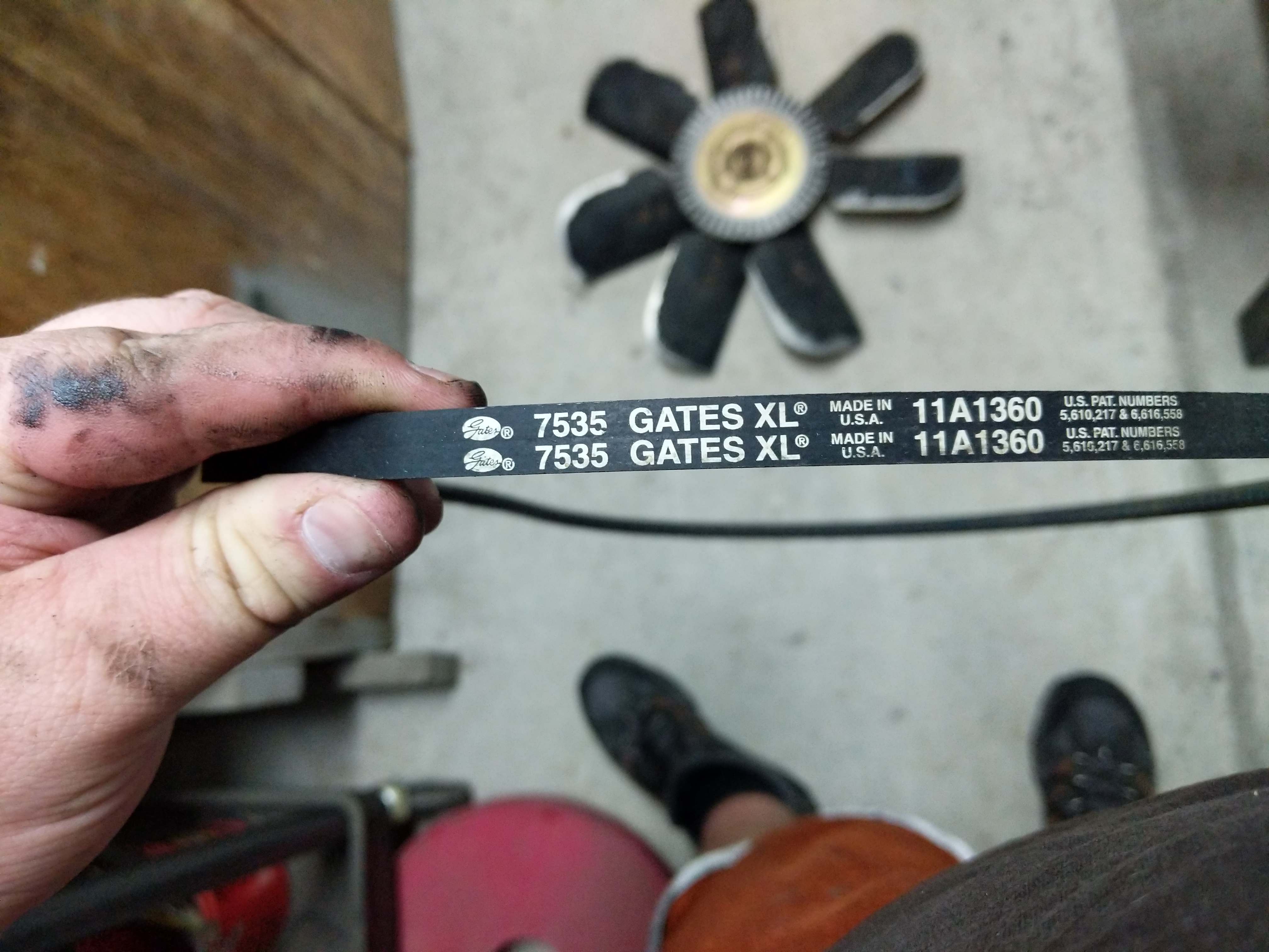
Power steering pump belt part number.Alternator and A/C compressor belt part number.
I wrote down the part numbers in case I need more belts. The belts look fairly new so I am going to reuse them. With the belts removed I pulled off the water pump pulley to get a good look at the pump.
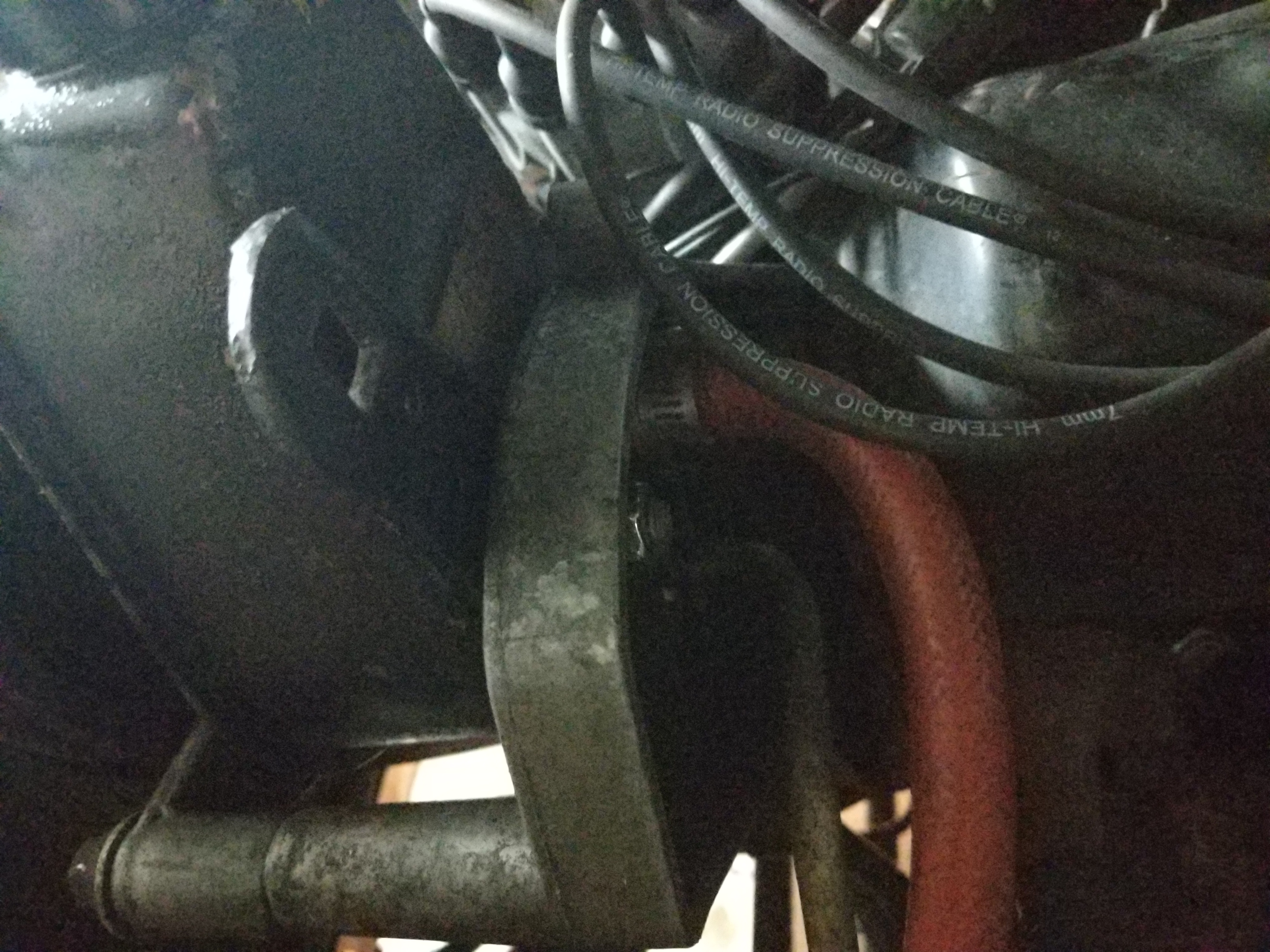
Rusty water pump.
Oh boi, previous mechanic RTV the pump on with Black RTV. Gonna be fun to remove. There are lots of bolts on this thing and brackets that attach to other accessories. I removed all the bolts and laid them out in order of how they came out. The alternator bracket and power steering bracket need to be loosened so the pump can full come off. Removing the pump was not actually that bad as the RTV did not have a good seal on the surface.
Cleaning up the filler neck of the radiator. Crack is visible now.
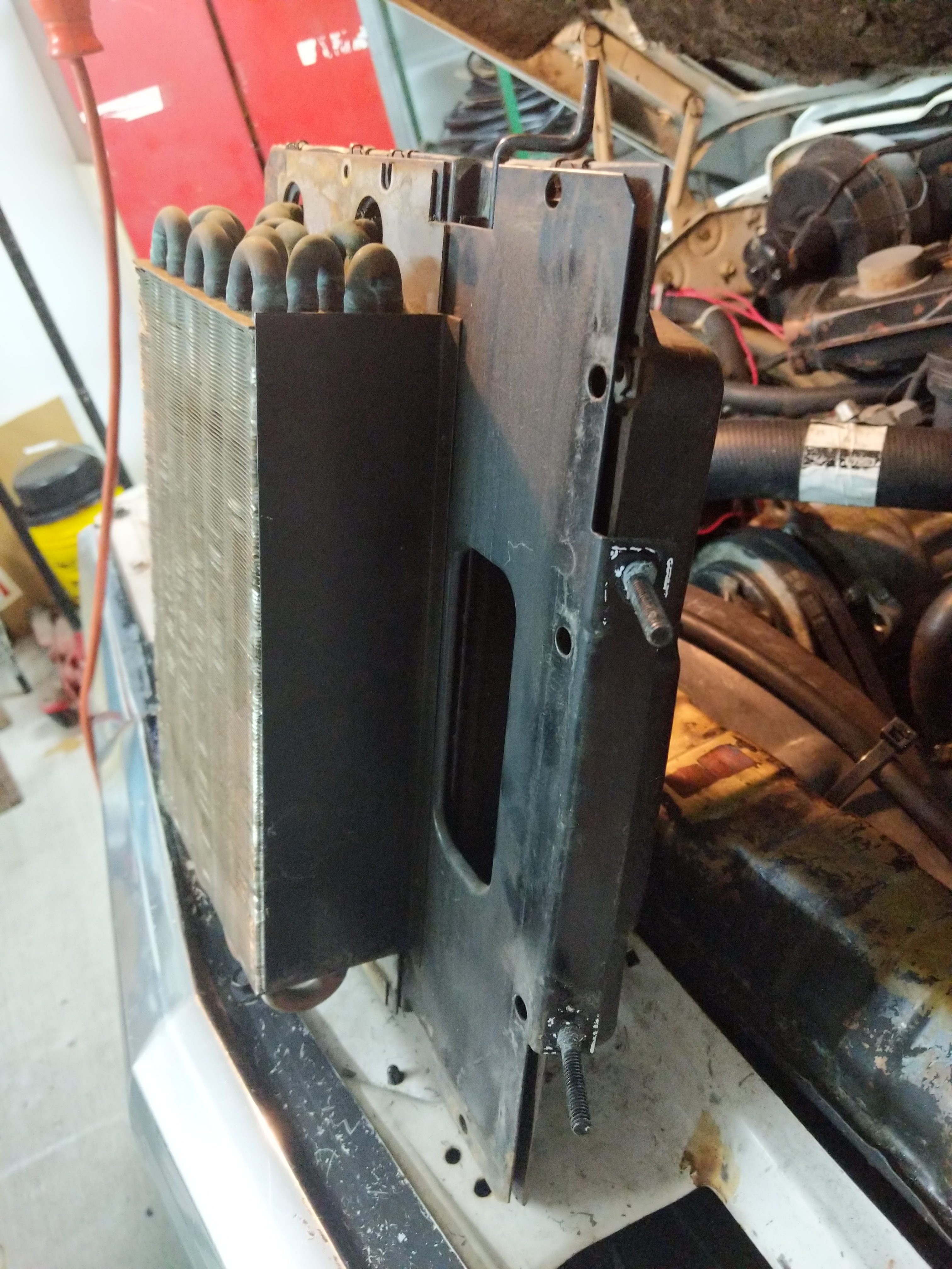
Before I tried brazing the filler neck of the radiator I first removed the fan shroud as It is made of plastic and I did not want to melt it.
I cleaned up the filler neck area with a brass wire brush on the drill.
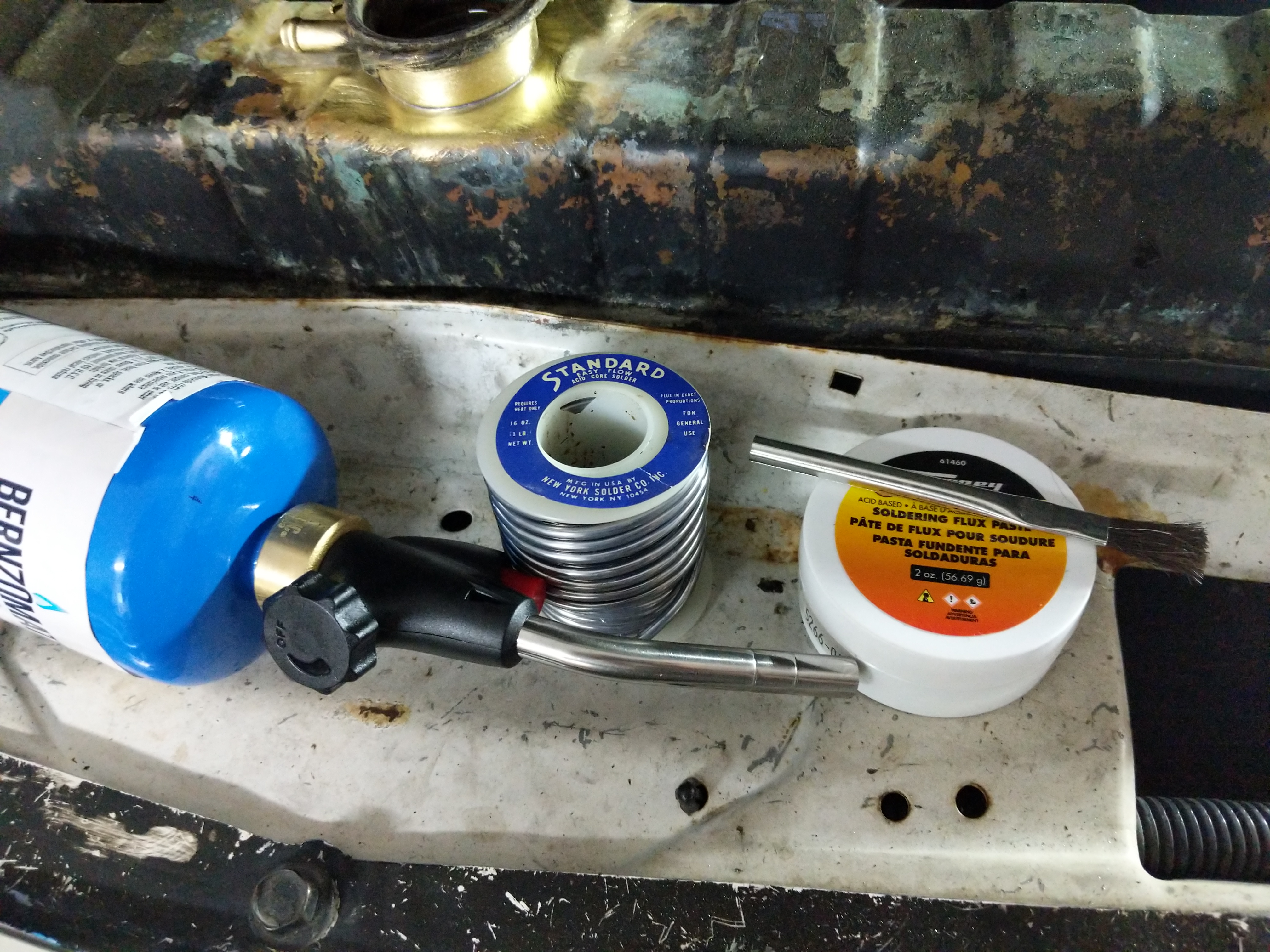
Tools used to braze the filler neck on the radiator.
I coated the filler neck joint with lots of acid based flux and then heated it up with the propane torch till I could pop it off with some pliers.
Removed filler neck for cleaning and rebrazing.
After the filler neck came off I cleaned up the mating surfaces with the brass wire brush on the drill. Then I coated both surfaces with more flux and pressed the filler neck back into the radiator. Then heated up the joint again and brazed it with the solder.
Filler neck after brazing.Close up showing the crack is gone.
Looks like I did a decent job. Will know at the end if it holds pressure :)
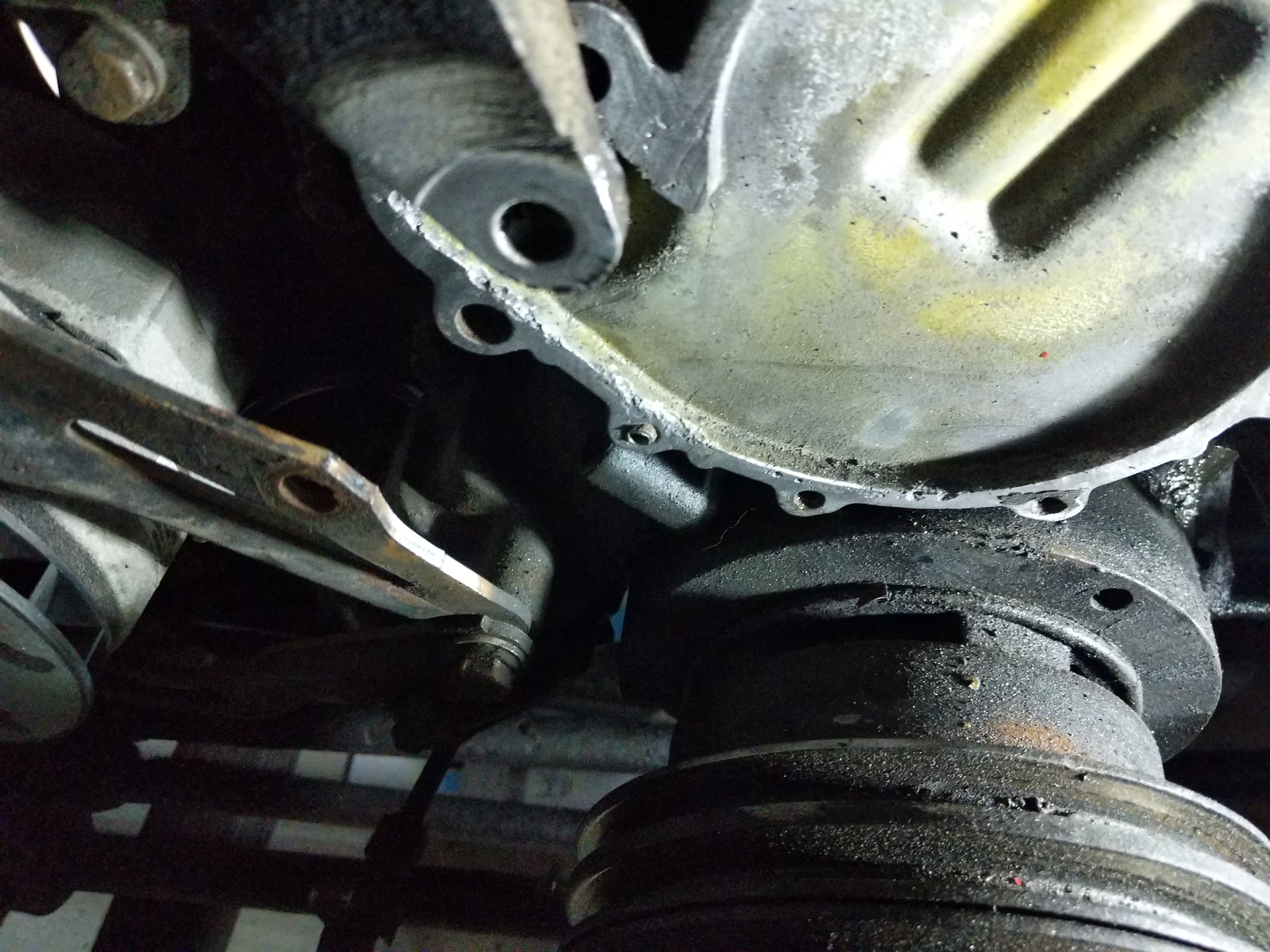
Cleaned up T-stat gasket surface.
Since the T-stat housing area and water pump mounting surface was so corroded I hit the entire area with the brass wire brush on the drill. Cleaned them right up.
Broken bolt on the water pump mounting area :X
During the clean up I found that the previous owner just left this broken bolt for me to find. Woooooooo….
Looks like someone already tried to extract it as there is a hole drilled into it.
I finished the job by drilling a 1/8″ pilot hole into it and then used a #7 drill bit to clean up the hole. I then put in a 1/4-20 tap to chase the threads. If I ever sell this engine to someone I would go back and drill it out and helicoil it but this fix will probably work for what I need.
T-stat installed!T-stat installation was next. On my water related gaskets I like to use Permatex High Tack Gasket Sealant on both sides of the gasket. I know some say to never use a sealant or use only blue RTV but I have never had to go back and redo a gasket with this stuff. Unlike RTV the High Tack Gasket Sealant is easy to clean up if you need to replace the part again in the future. If also sticks to the housings better which is great when you do not have mounting/alignment dowels.
After the T-stat housing I installed the water pump and put the bolts back in the same way they came out. I looked up the torque numbers in the Factory Service Manual and torqued the T-stat housing and water pump to spec.
Removing the studs from old water pump.
I then removed the studs from the old water pump using the stacked nut method. These studs need to be reused on the new pump.
Fan clutch studs installed.
Then I put the studs on the water pump. Then I put the water pump pulley on and reinstalled the belts but kept them loose till the end as I wanted to make sure I did not have to remove them later.
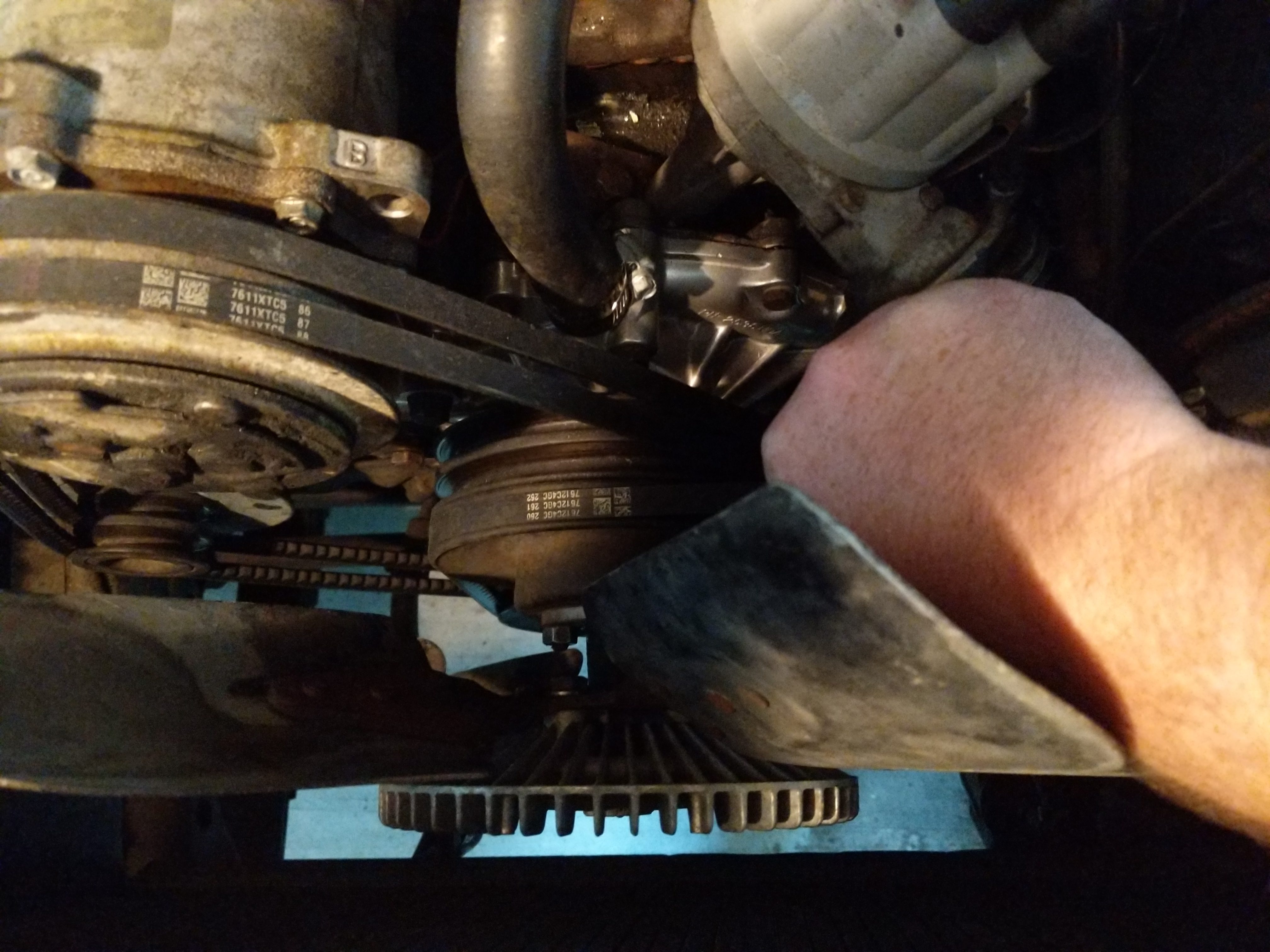
Using the belts to get friction while tightening the fan clutch stud nuts.
I then installed the fan clutch/fan assembly. To prevent the pulley from rotating as I was tightening them I used one hand to press down the belts which prevent it from rotating.
Installing the fan shroud was the last part of finishing up the front of the engine for this project.
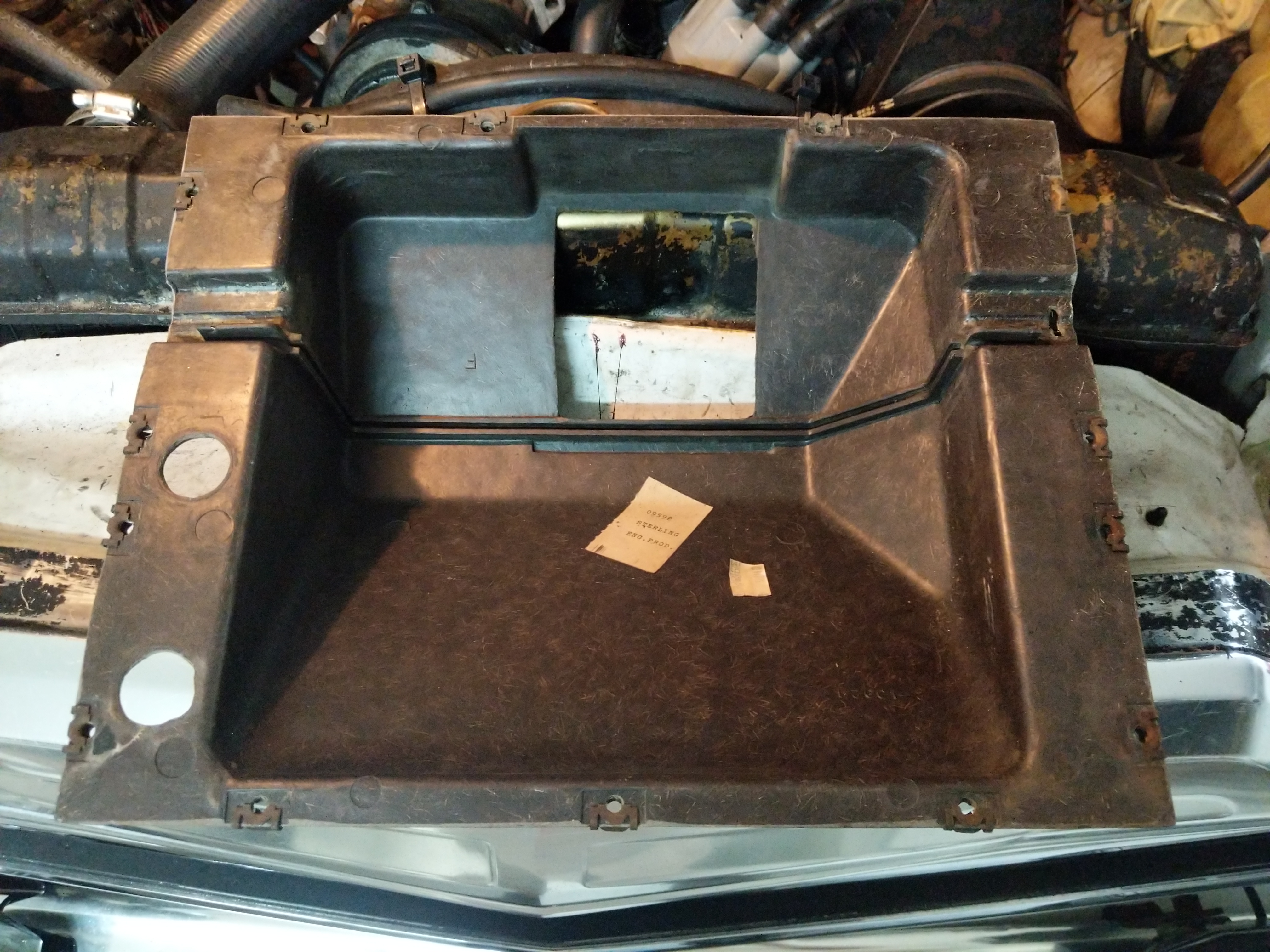
Removing the heater box. Two bolts and the blend door cable need to be removed from the engine side.
Now I wanted to clean out the heater core box since I had the coolant out of the heater core.
First I started by removing the two external bolts and the blend door cable on the top of the heater box.
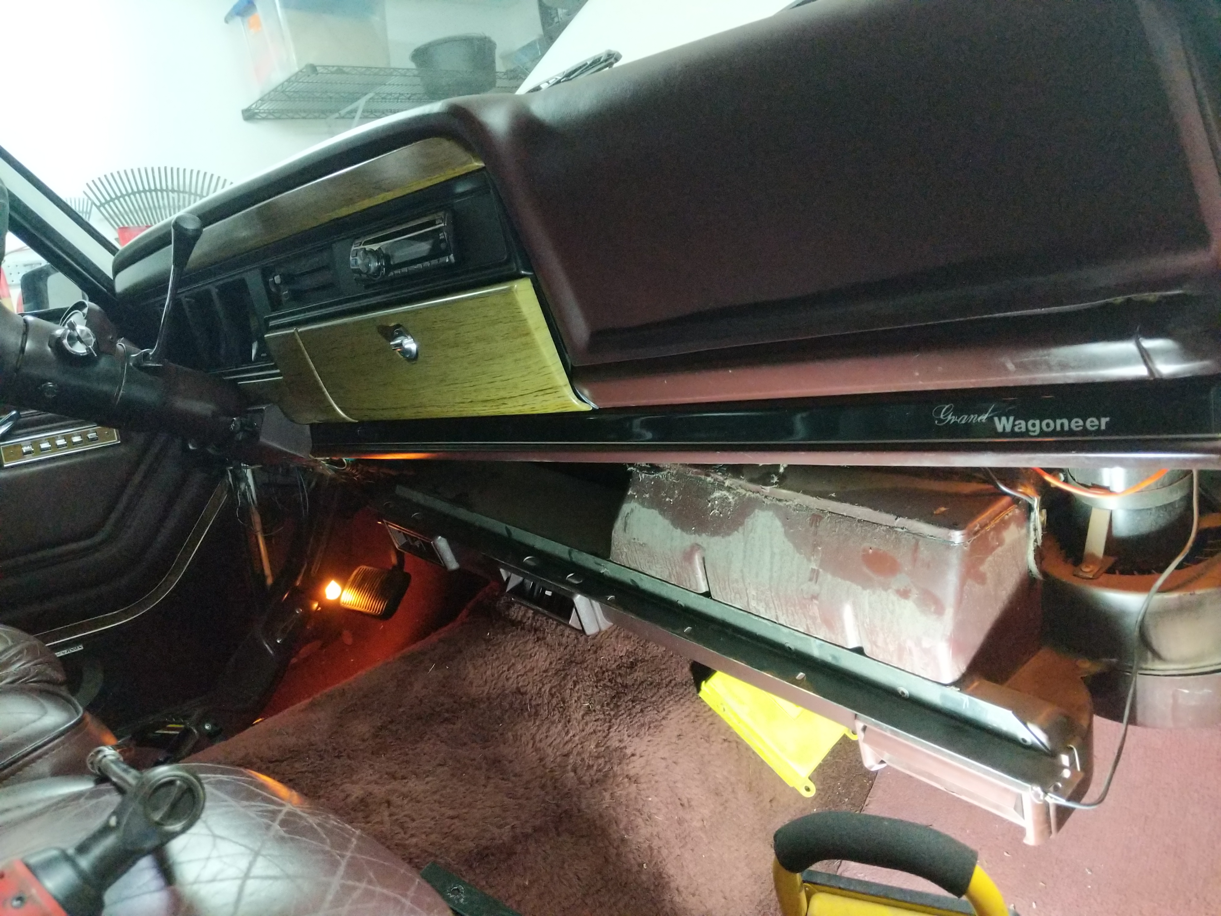
Dropping the A/C module under the dash.
On the inside there are two more bolts that hold on the heater box. To get to these bolts the A/C module needs to be dropped from the dash. The A/C does not need to be discharged for this. There are around 6-8 bolts that hold it up under the dash. After removing the box kinda just falls down.
Wobble extensions to remove the behind dash bolts.Where to snake the socket.
The easiest way I found to do this is to use lots of wobble extensions on a deep socket and snake this contraption in between the A/C module and the dash. Makes it fairly painless.
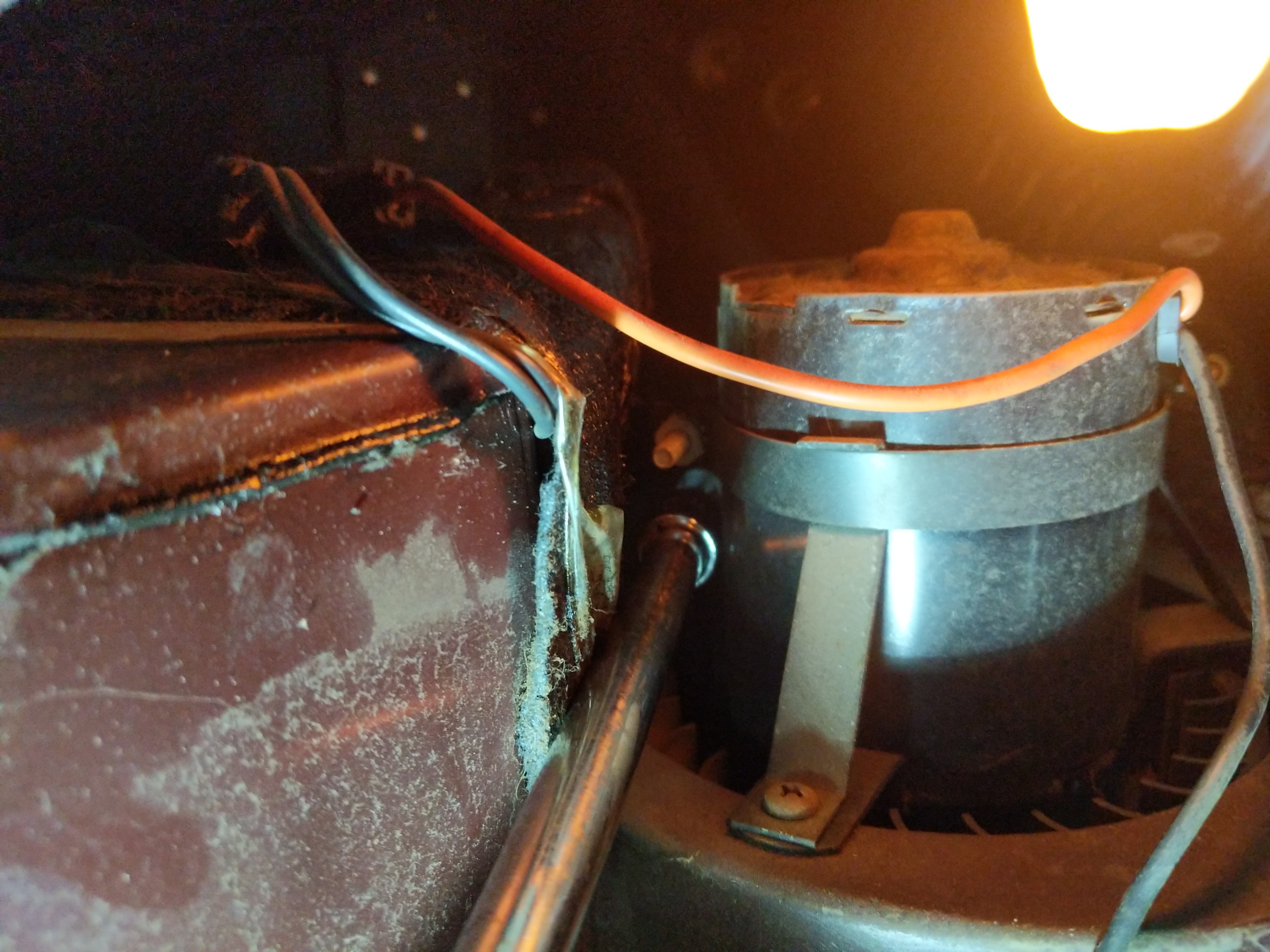
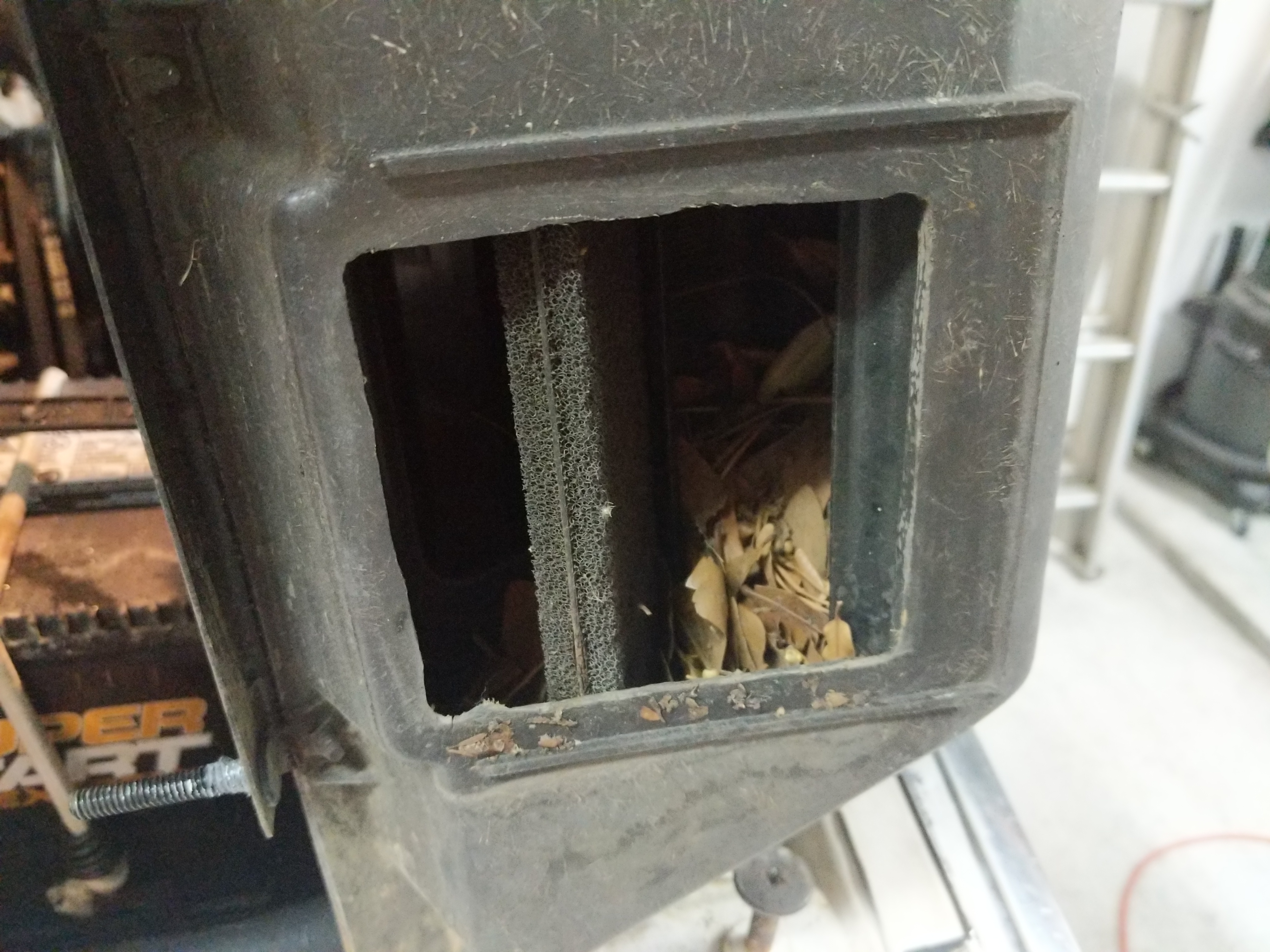
Lots of leaves built up in the heater box.
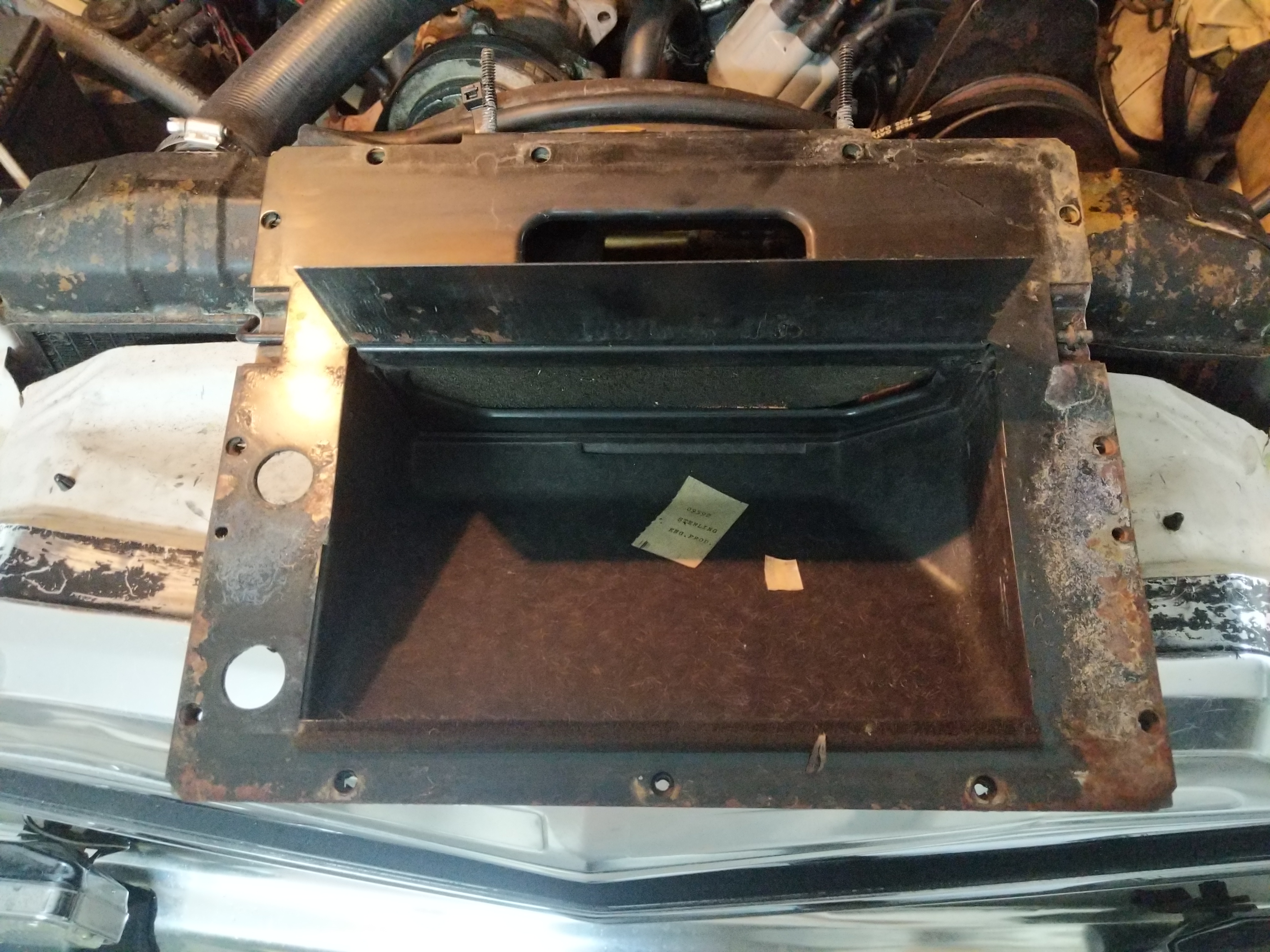
Then pull the heater box from the engine compartment. Mine had quite a bit of leaves that prevented the blend door from moving all the way.
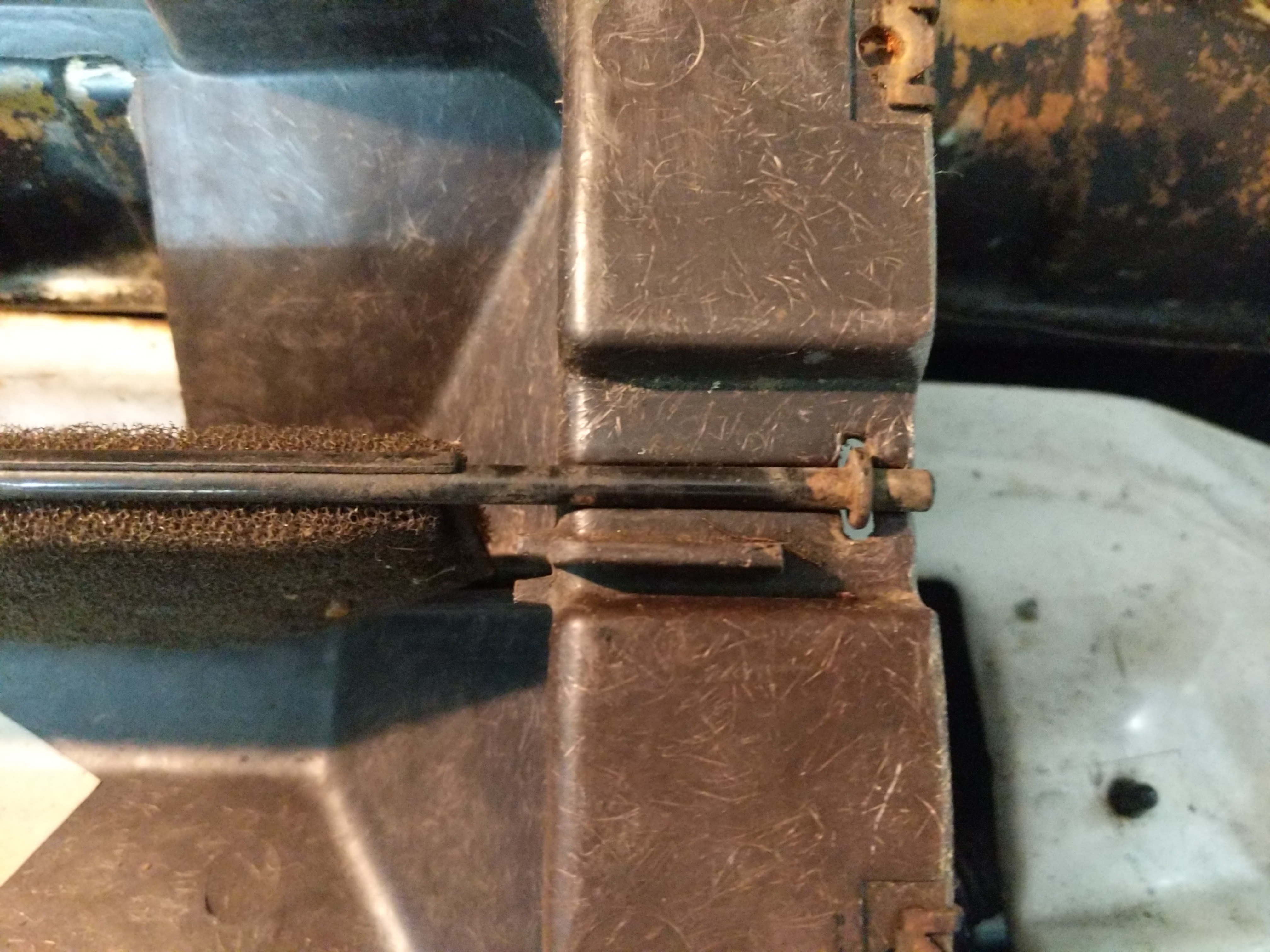
The heater box opens up by removing all the bolts on the outside. There are five pieces; two external fiberglass shells, inner metal plate, blend door, and the heater core.
I took my heater box all apart and cleaned it up. Then I reassembled it.
External shell ready for reassembly.Reassembly of the bottom of the blend door.Reassembly of the top of the blend door.Metal inner plate installed.Heater core installed. View 1.Heater core installed. View 2.Heater core installed. View 3.
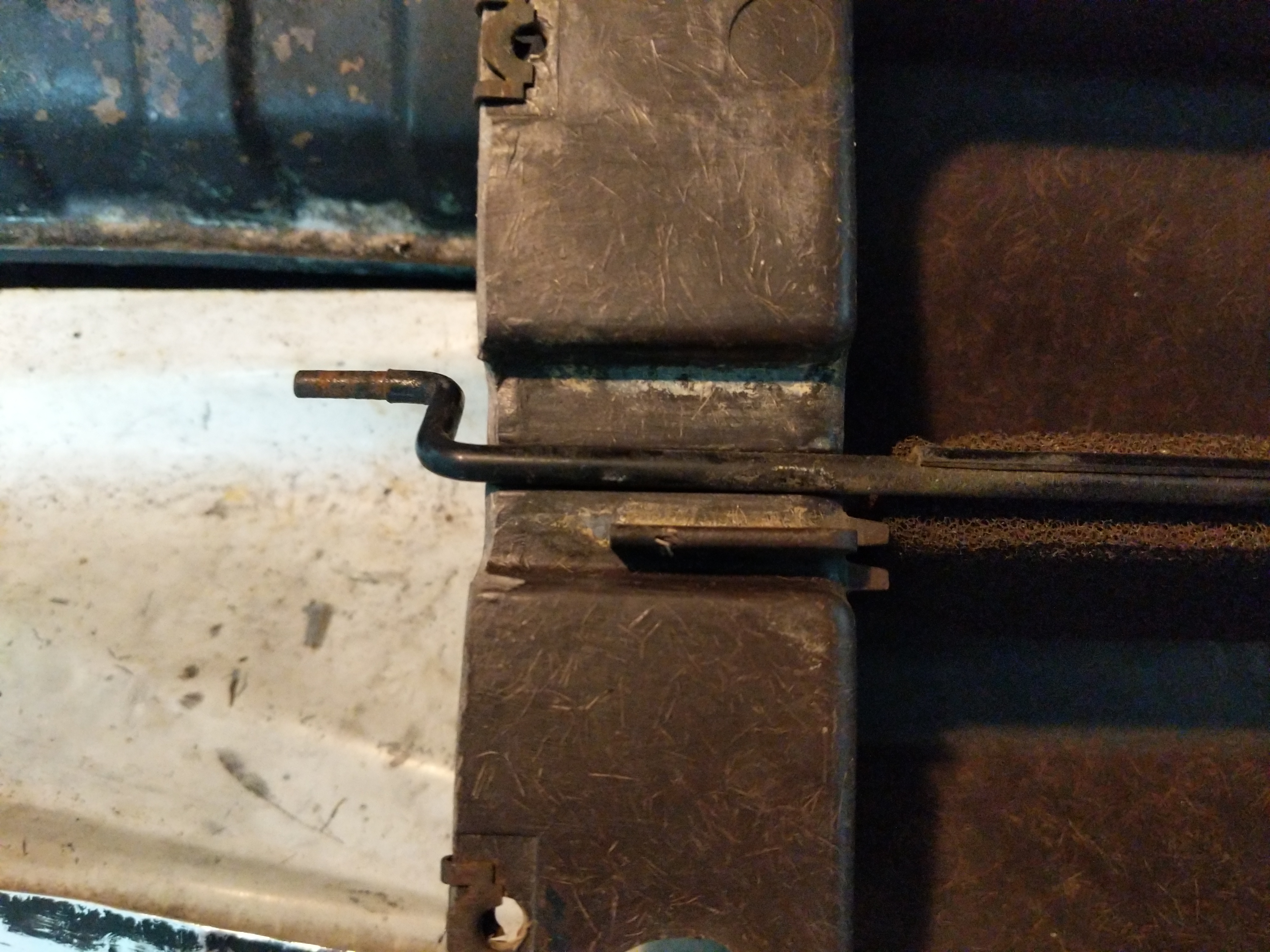
First put the blend door back into the shell, next put the metal inner plate in. Next install the heater core and then the top of the shell. When putting the bolts back in do not tighten them up all the way till all the bolts and the heater core tabs at the top and bottom are all lined up.
Reinstalled heater box blend door cable.
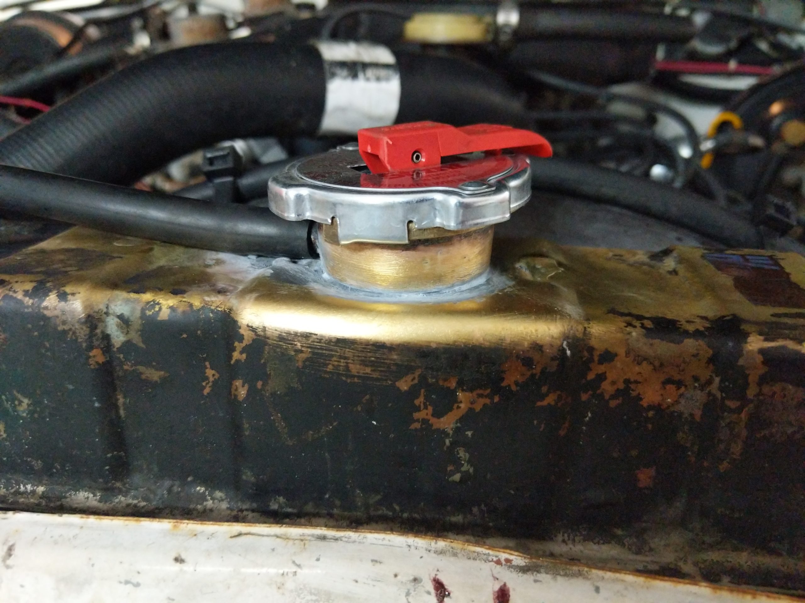
With the box cleaned up I reinstalled the heater box and put the dash back together. Then reattached the blend door cable.I hooked all the hoses back up on the radiator and heater core and refilled the engine with new coolant and put a new radiator cap on.
New radiator cap and the brazing seems to be holding pressure!
A trip around the block and to the grocery store shows that the Wagoneer has stopped puking radiator fluid! Success so far!
This past Friday I picked up a 1990 Jeep Grand Wagoneer. It was in Dallas, Tx so I took the Friday off and drove up with my Dad and picked it up. Drove back to Houston with it (~300miles) was a pretty fun road trip!
Wagoneer in the driveway after the long day.
It is a fully loaded Grand Wagoneer with all the trimmings. Everything functions except the rear window wiper and sprayer. The wiper looks to just be a bad wiring and the sprayer is missing from the back. If you know where to get a sprayer let me know….they seem to be unobtainium.
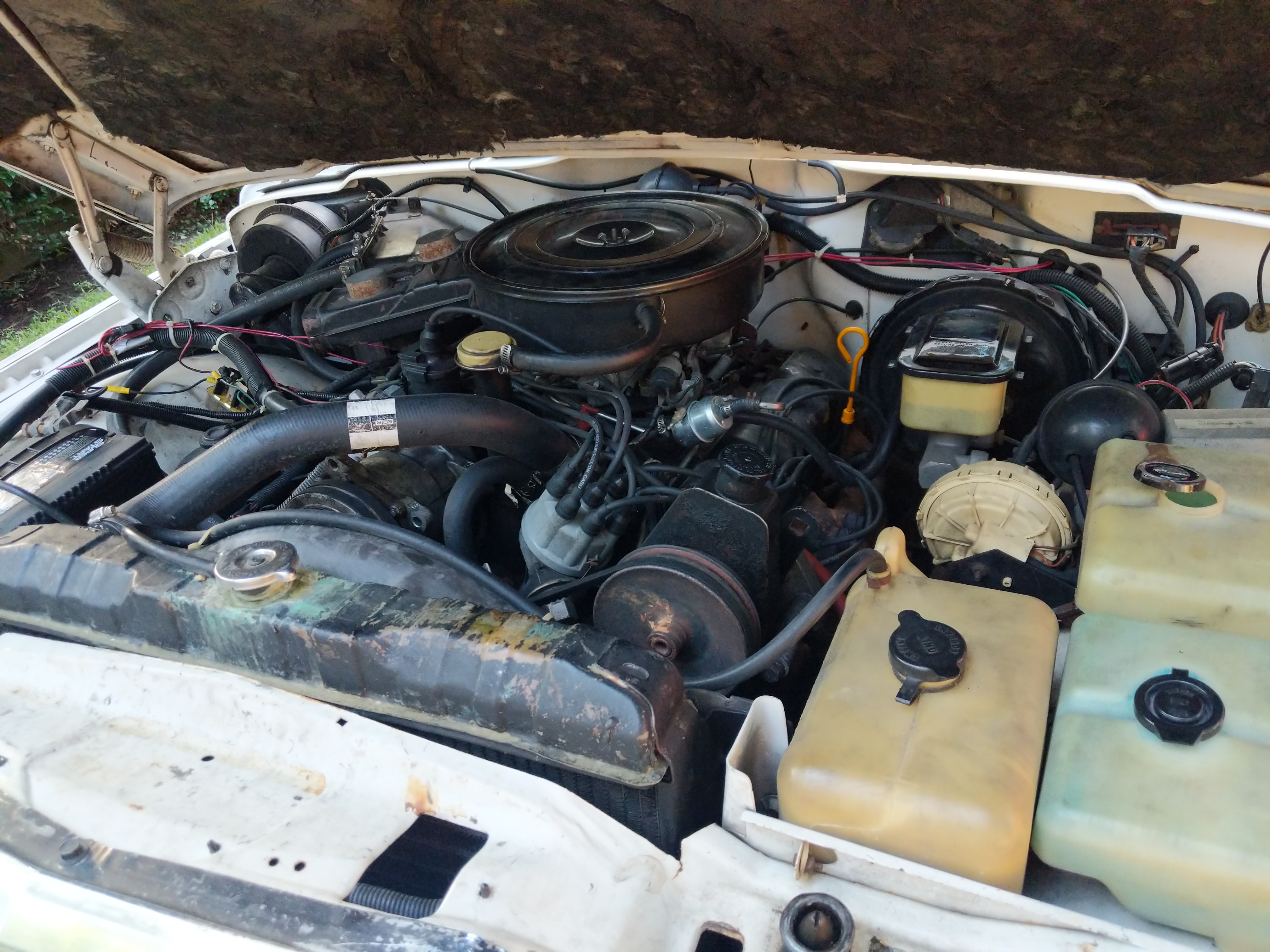
5.9L of raw Murica fury.
The 5.9L AMC 360 engine is mostly intact and runs ok. The valve seals are blown so the engine smokes a bit on start up.
When I got the Wagoneer the oil pressure gauge wasn’t working so I just had to hope it had oil pressure to make it back to Houston.
The first thing I did was an engine oil flush and replaced the oil pressure sender and wire. Engine idles at 40psi cold and ~10psi hot. The hot 10psi is not ideal but it does have 188K miles on it. I am debating rebuilding the oil pump or just leaving it.
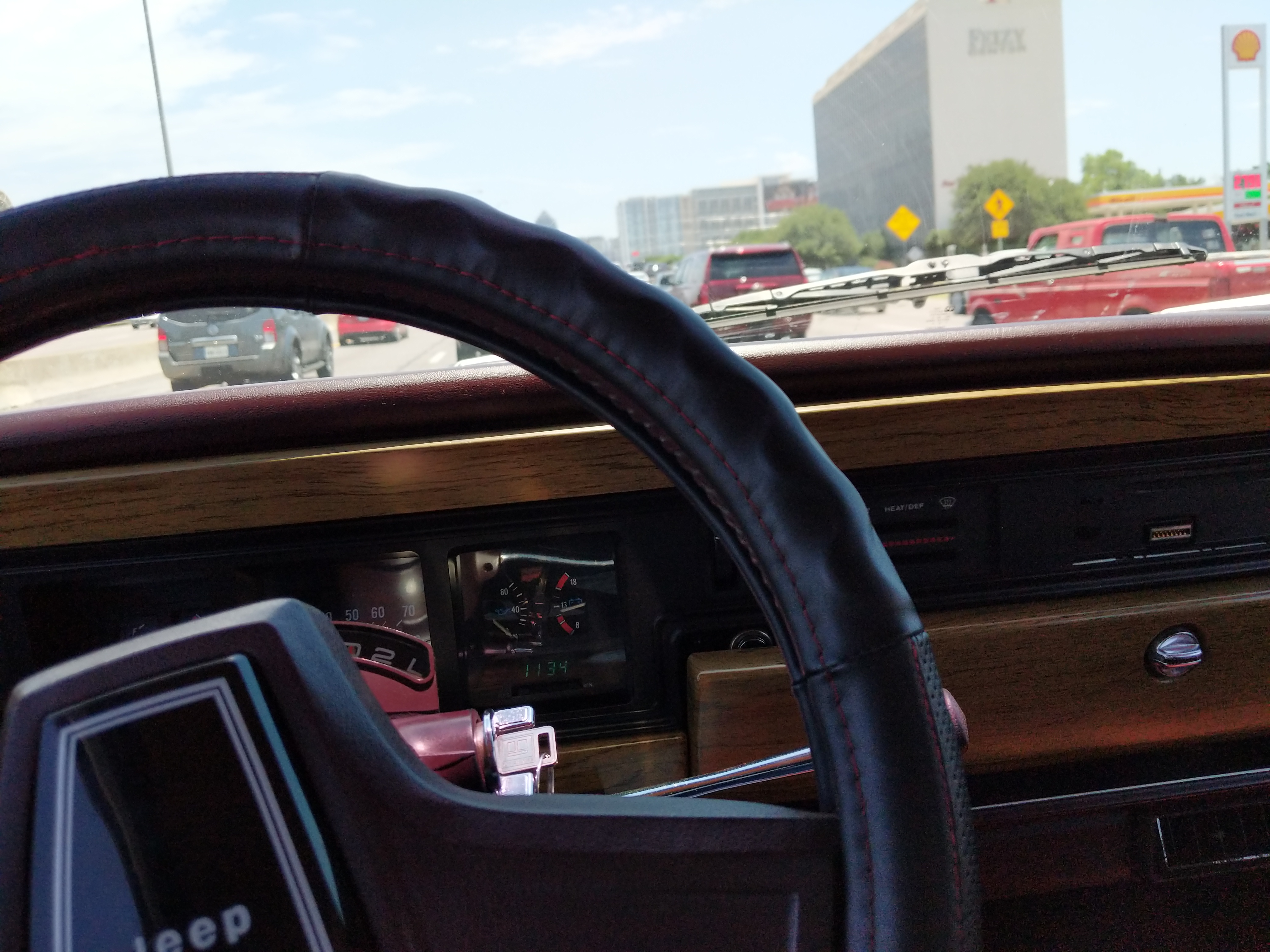
Stuck in Dallas traffic after picking up the Wagoneer.
My long term plan with the Wagoneer is to not 100% restore it but just make it nice. Fix all the problems, modernize the electronics, and swap in a LQ4 V8 engine and 4/5 speed automatic transmission. To get there however will take time.
My short term goal is to turn it into a decent daily driver and rock the AMC 360 engine while I fix the major problems and figure out how much I want to restore.
Here is the “short term” list.
Cooling System
Radiator has a cracked filler neck. Fix the copper/brass radiator by soldering/brazing the crack
Replace T-stat
Replace Water Pump
Flush System
Replace temperature sender
Engine
Another engine oil flush
Open valve covers to check rockers and push rods
New spark plugs
Transmission
Oil flush
New filter
New fluid
Fuel System
Repair gas tank skid
Clean tank
Replace rubber hoses and steel if needed
New fuel sending unit
Tank vent and hoses replacement
New fuel filter
A/C (very important!)
Recharge R12
Fix electrical
Steering
Replace leaking steering gear box
New hydraulic hoses
New fluid for power steering
Ball joints
Tie rod ends
Suspension
Replace sagging leaf springs with new suspension
Drivetrain
Flush and replace oil in transfer case
U-Joints
Rebuild Axles
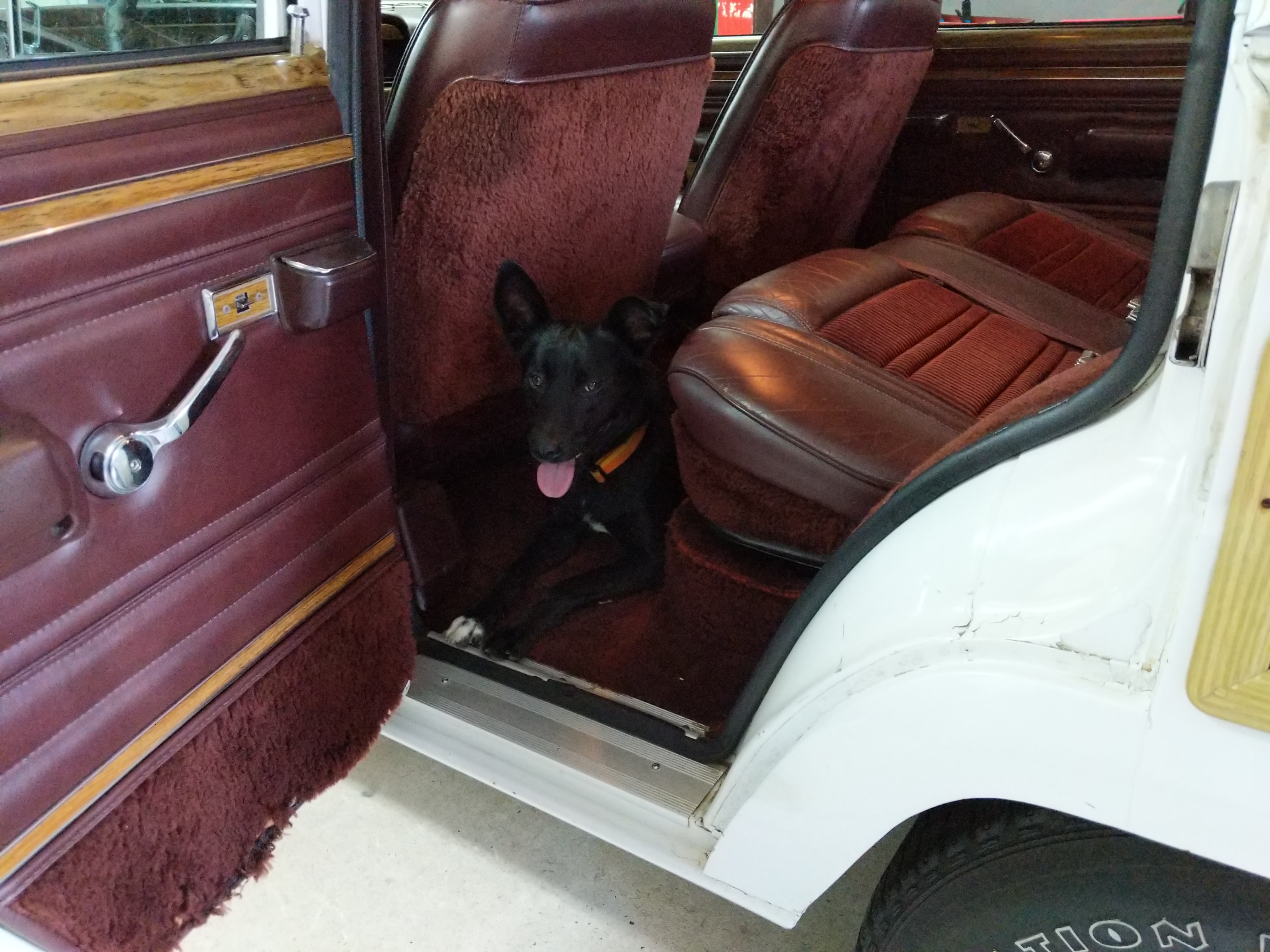
King enjoying the Wagoneer.
Sounds like a lot but afterwards it should be a nice daily. The Wagoneer already rides like your sofa going 70mph down the freeway so it can only get better!