
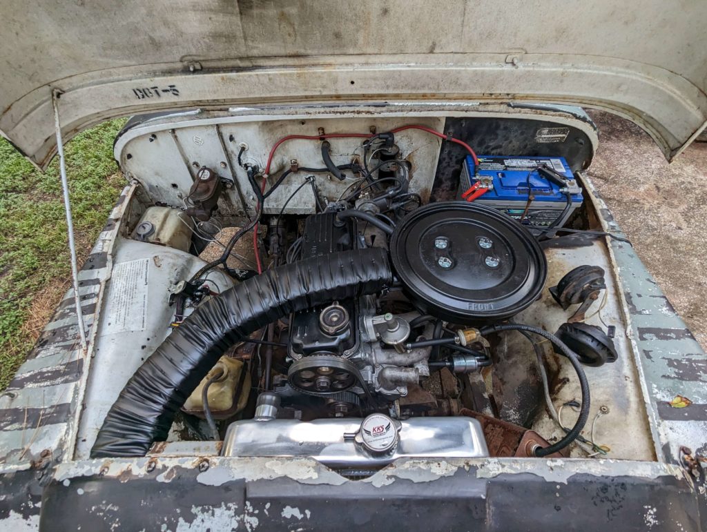
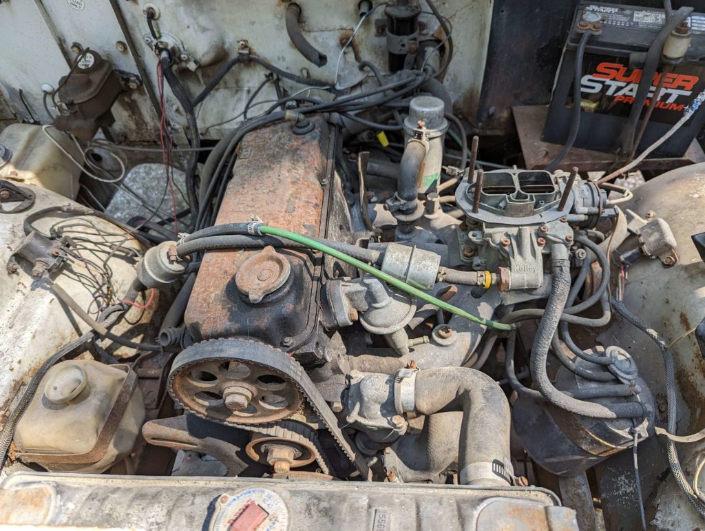
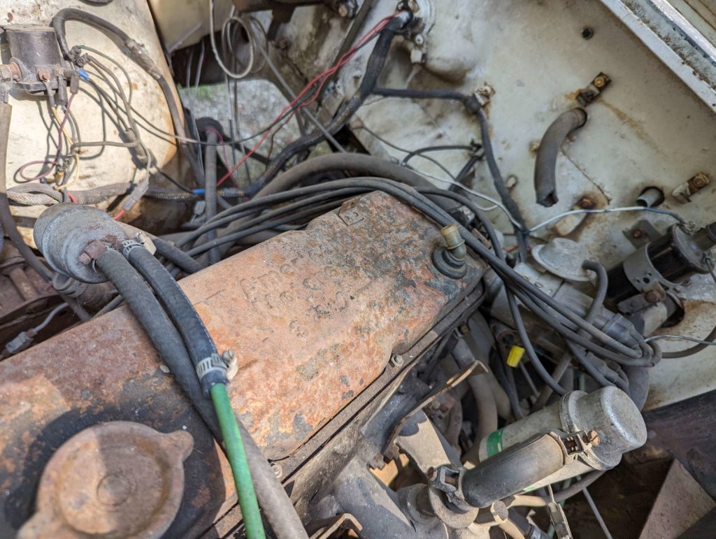
The original radiator looks to have been clearanced with the cooling fan at one point, the seal at the top of the tank is split, and the brackets are pretty rusted.

Instead of trying to fix up the original radiator, I looked for a replacement. The DJ doesn’t share a radiator with the CJ chassis of Jeeps. The front opening is smaller on the DJ. A couple companies make replacement radiators but not for the DJ-5G. The Audi engine flipped the sides for the intake and outtake for the radiator and was the only engine for the DJ that was like this. Safe to say, no one makes a direct replacement for the G model.
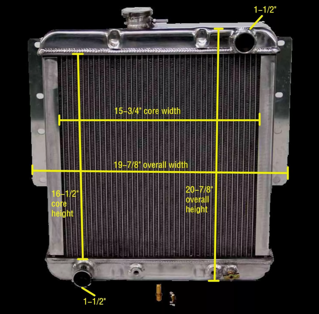
So I ordered a radiator for the other models of the DJ that is made by “KKS”. If you search around for “KKS 3 ROW ALLALUMINUM RADIATOR FIT 1966-1974 Jeep DJ5 CAR 1966-1974 3.8L 4.2L” you will find it.
The radiator fit perfect into the opening but we need to hook it up!
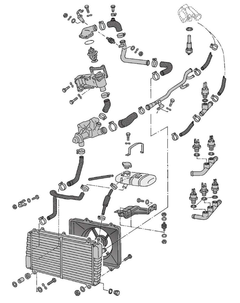
This is a diagram of the Porsche 924 cooling system.
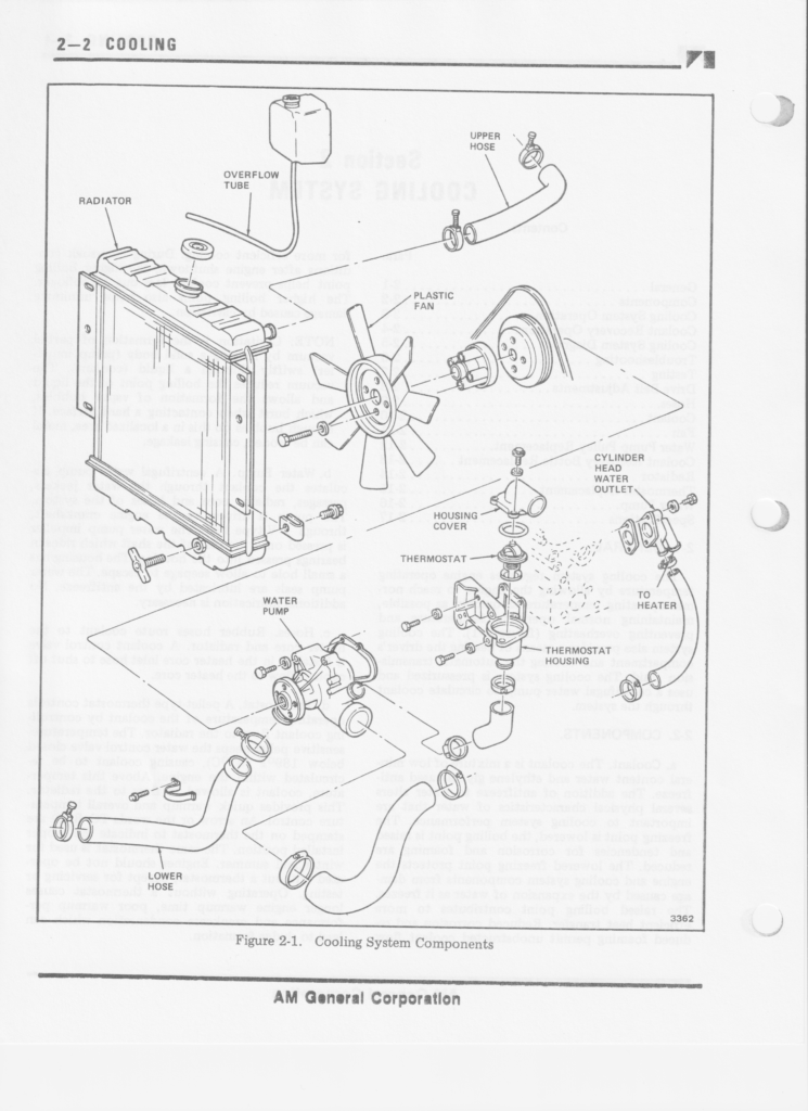
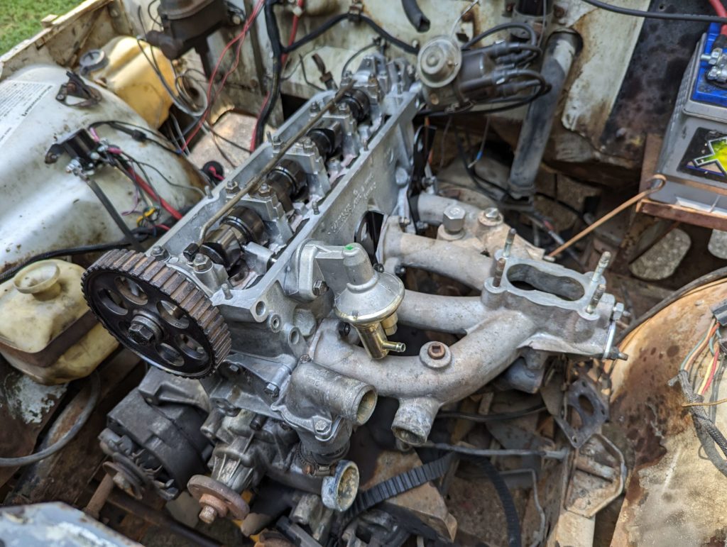
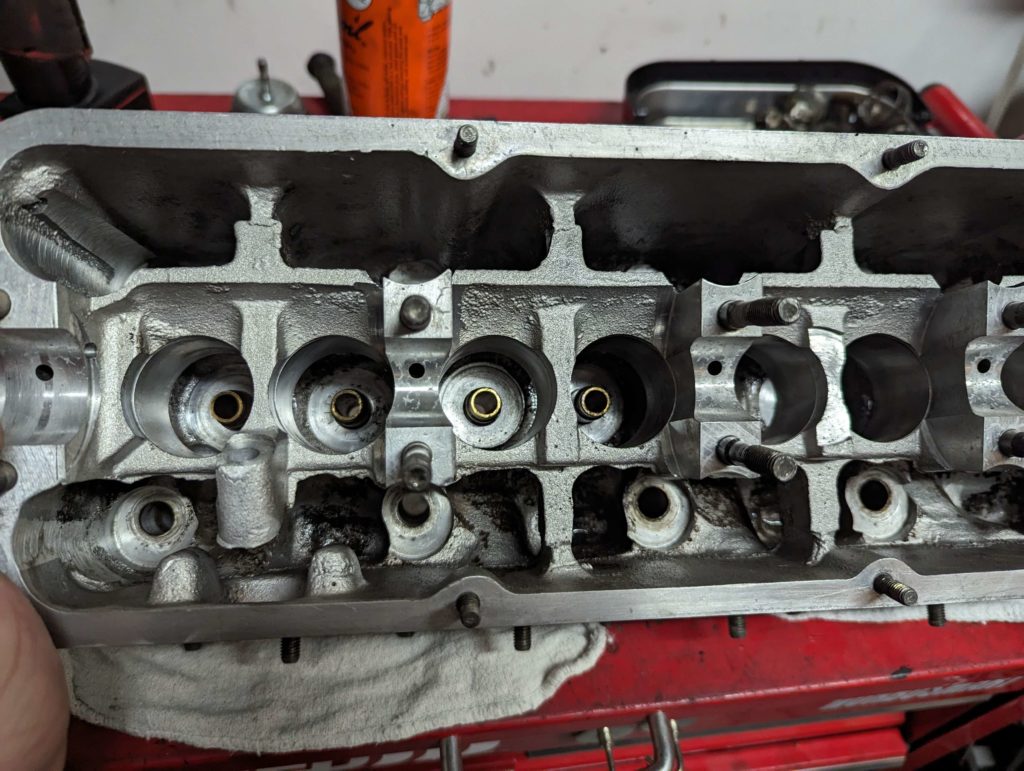
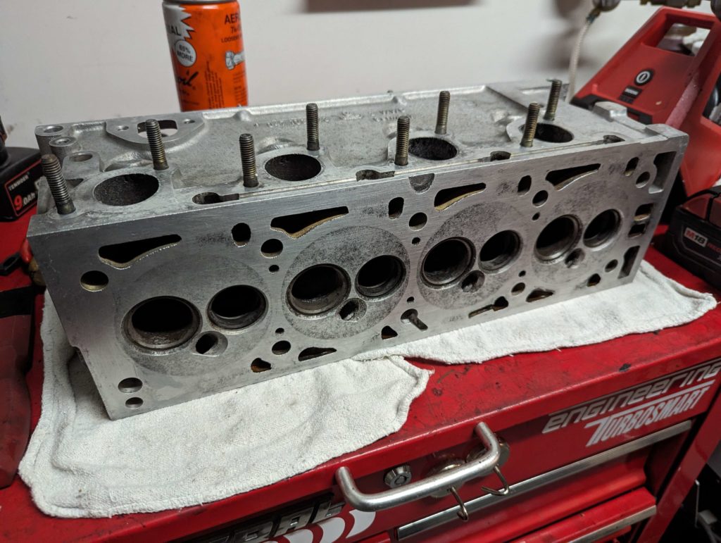
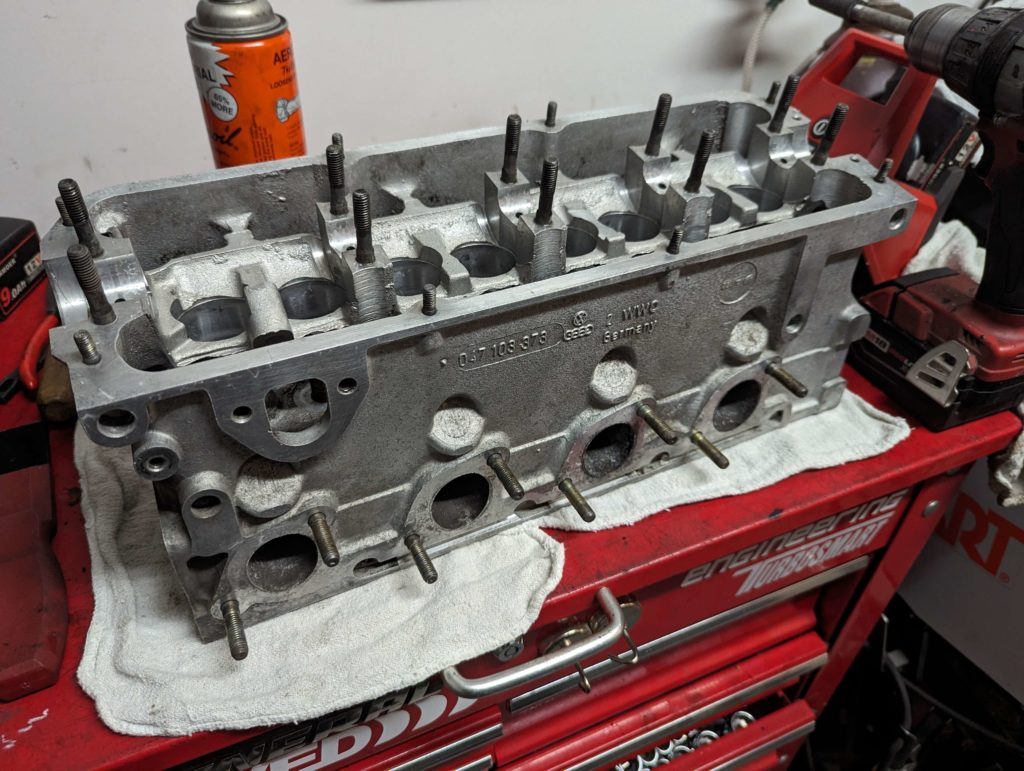
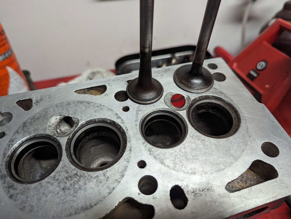
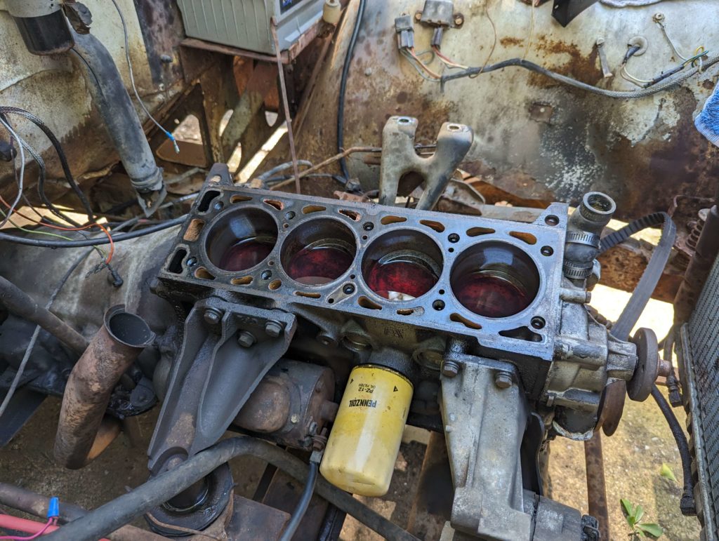
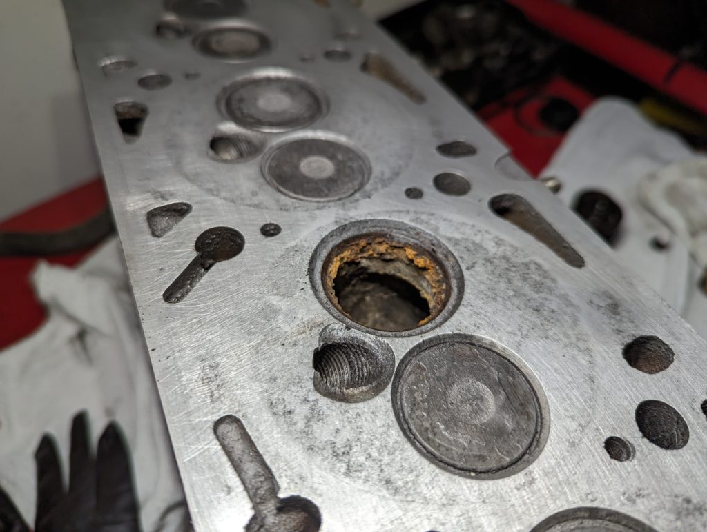
And this is the cooling diagram for the DJ-5G. I wanted to look at these cause the backside of the block has a coolant passage that then runs into the intake to heat up the fuel mixture.
The lower radiator hose was pretty easy to get hooked up with a Gates 25804 Vulco-Flex II Flexible Hose.

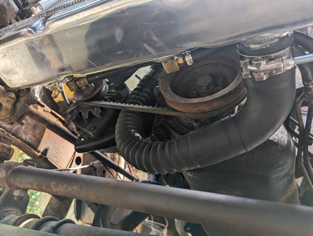
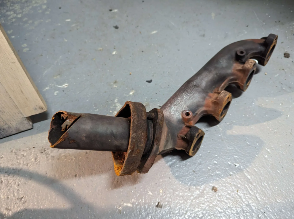
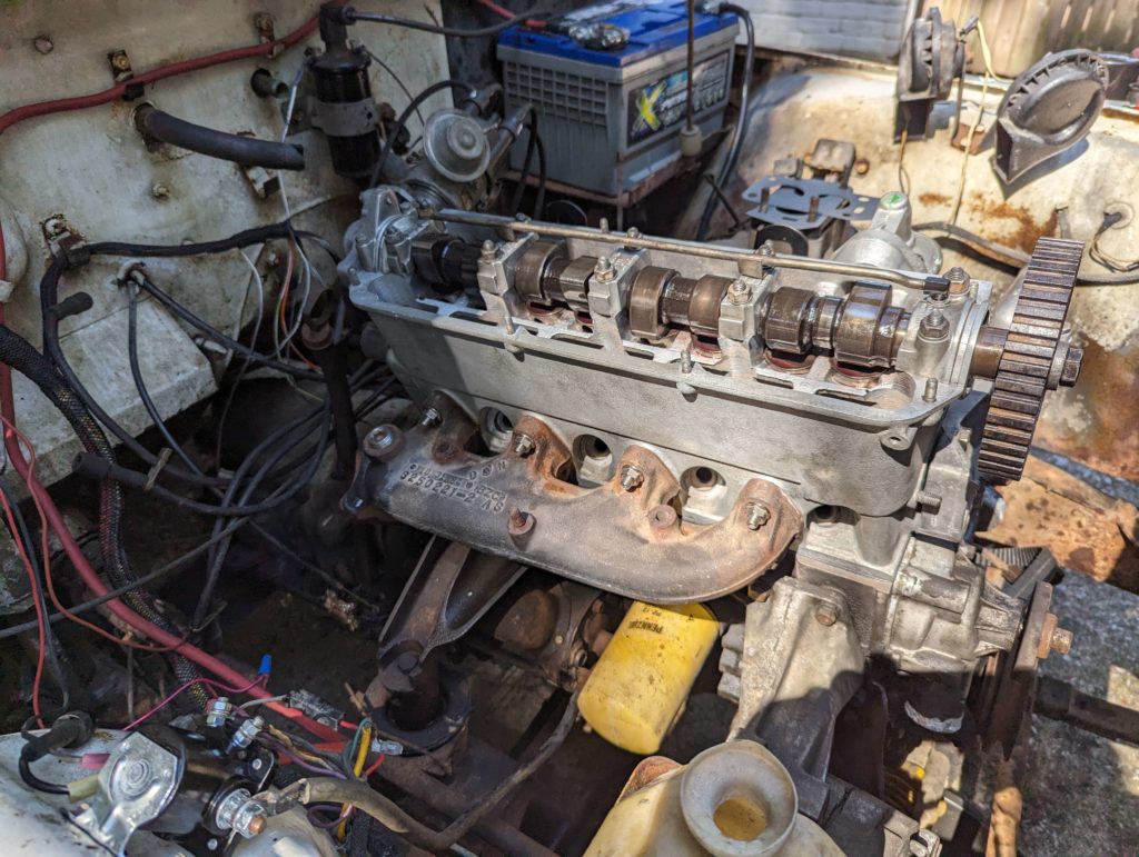
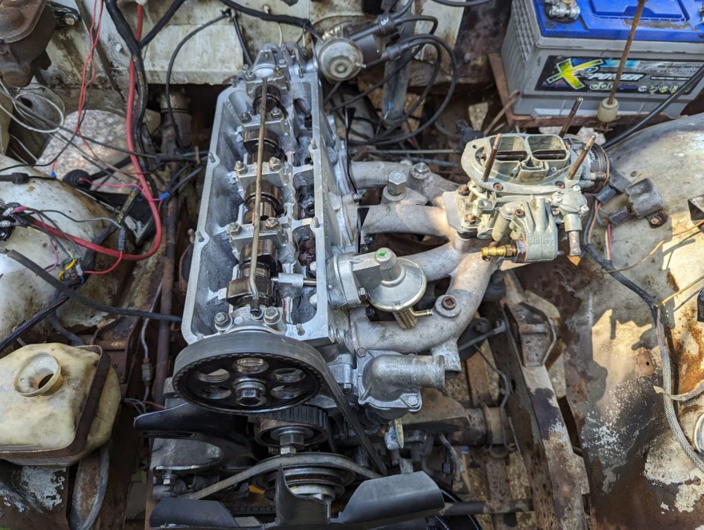
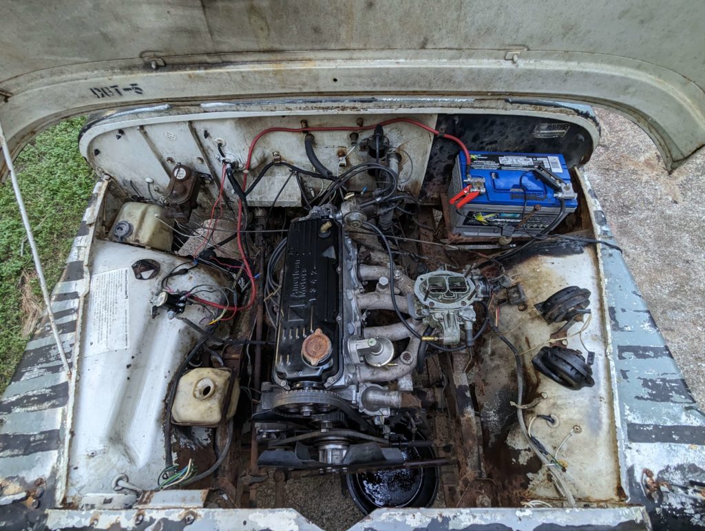
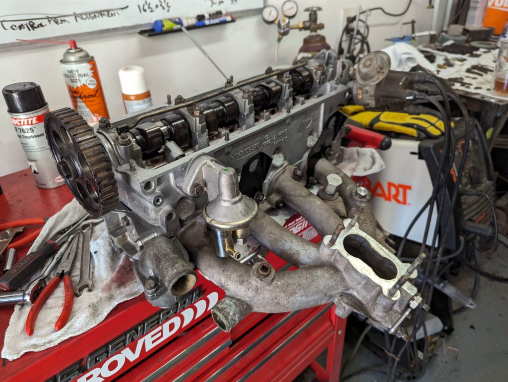
The back of the engine needed a hose block off and a some piece of heat core hose to get the intake heater hooked up.
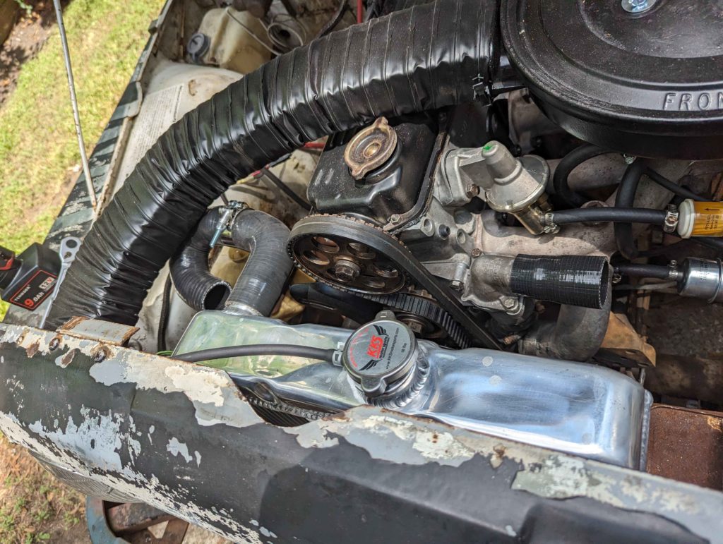
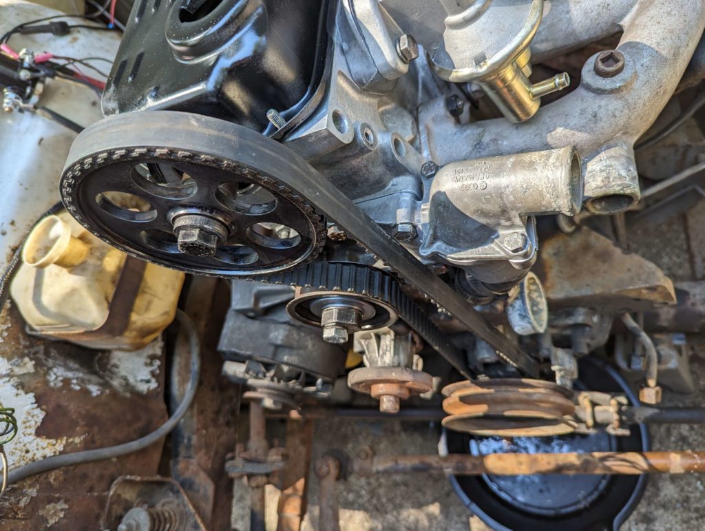
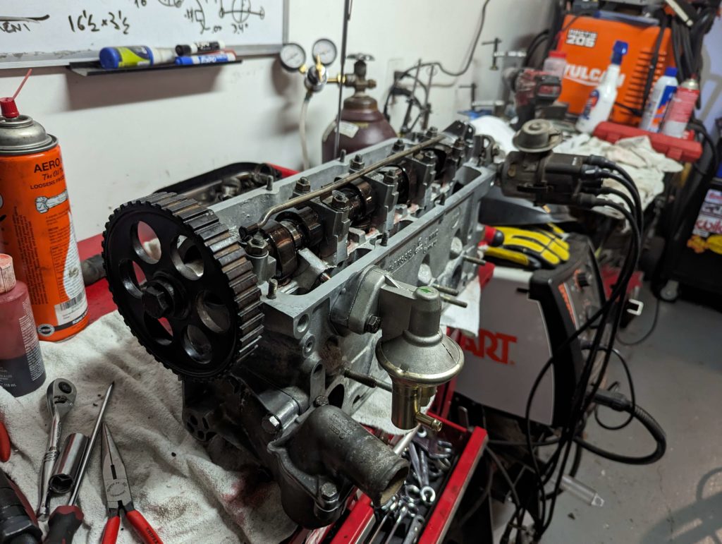
Now the upper radiator hose is more of a problem. The cog for the cam timing prevents turning directly right. We can’t send the radiator hose over the engine because that would bring it above the coolant system above the radiator cap and would make bleeding the system a pain. This makes the only option to go down and to the left.
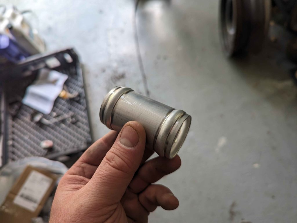
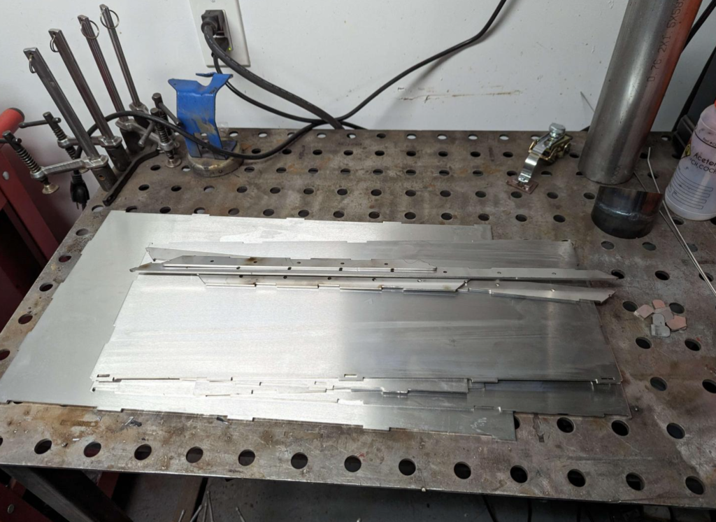
To join the hoses together, I cut some aluminum tubes and bead rolled them.
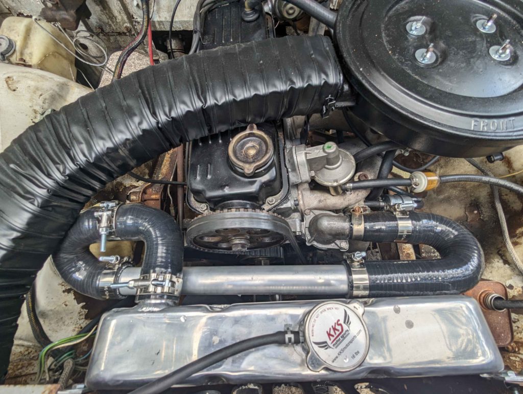
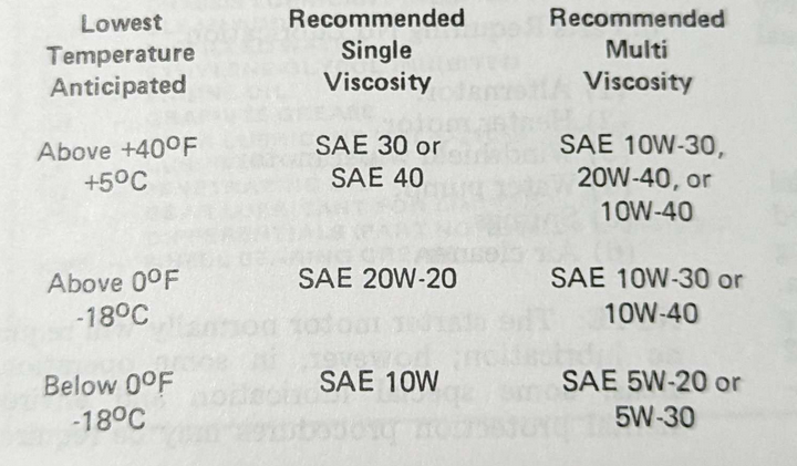
Now we can fill the system with coolant and bring the engine up to temperature. I set the idle and timing to 800 rpm with the transmission in drive with 10 degrees advanced. This is what the service manual specifies. The engine does seem to like a bit more advance.


