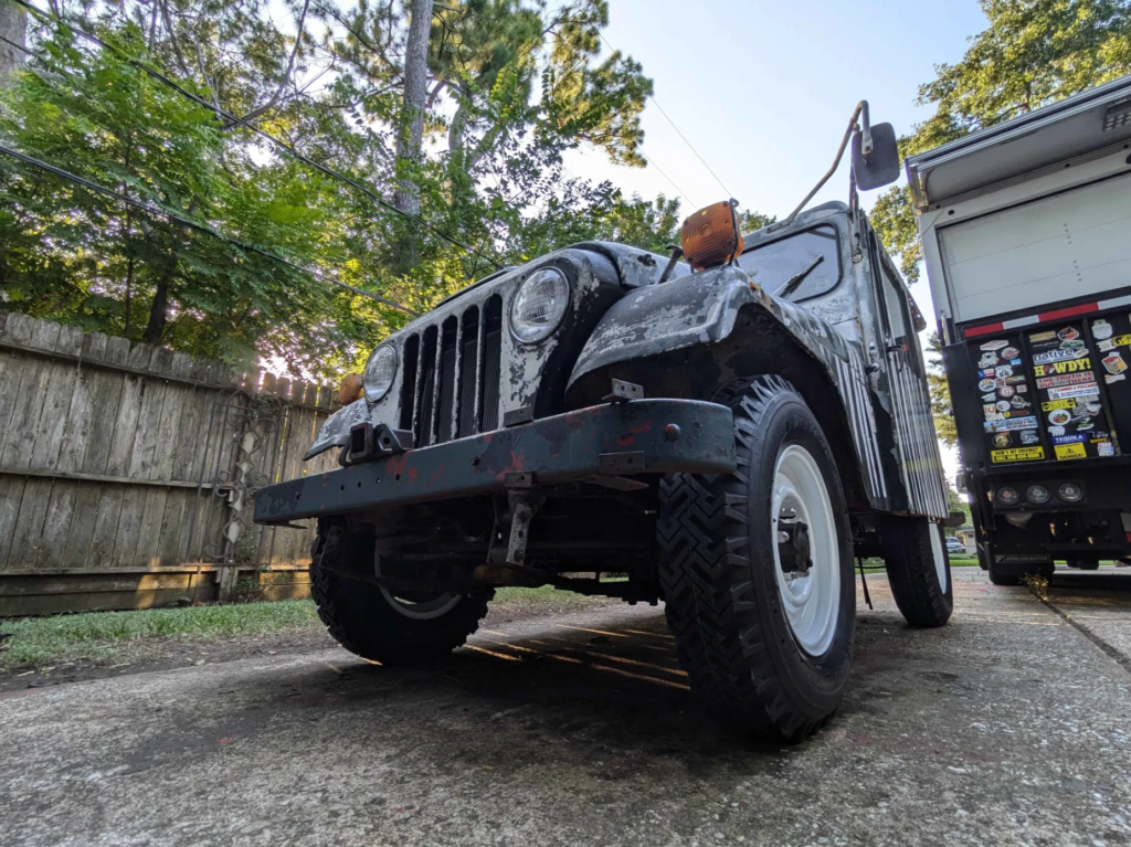
The Jeep isn’t done but enough of the Jeep works to make it drivable!
Category Archives: Car Stuff
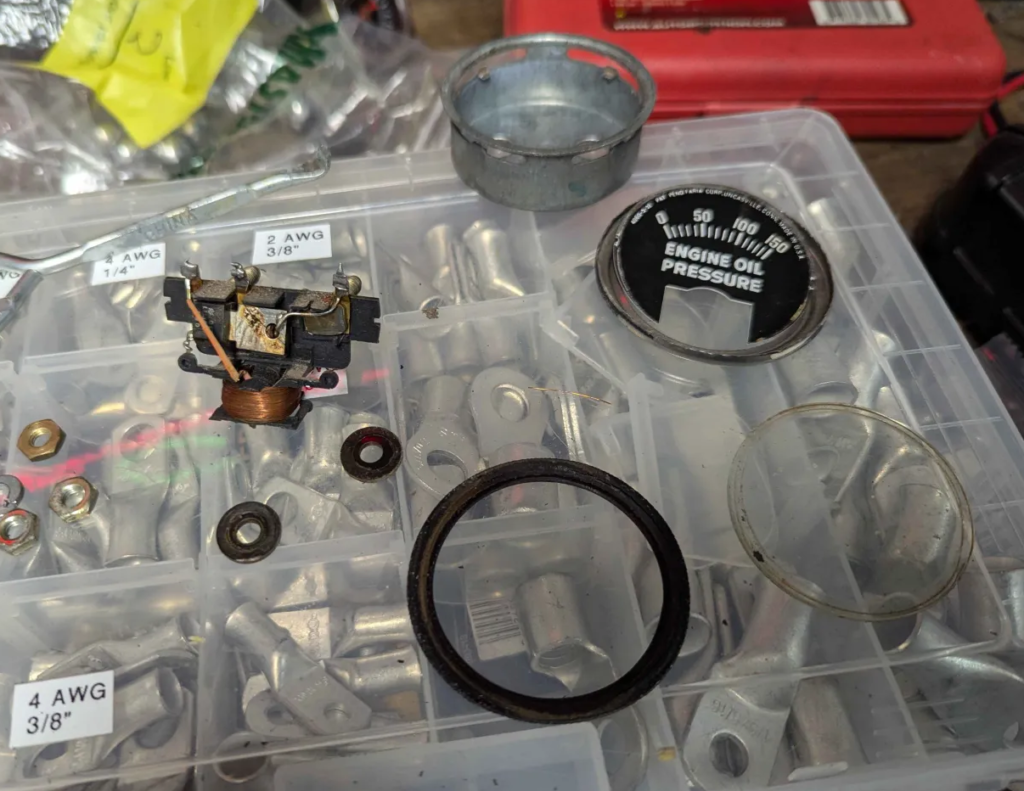
Checking the Temperature Sensor and Gauge
After getting all the electrical working on the Jeep, I noticed that the only gauge not working was the temperature gauge. The gauge would always keep in the “Cold” region no matter how hot the engine or sensor got.
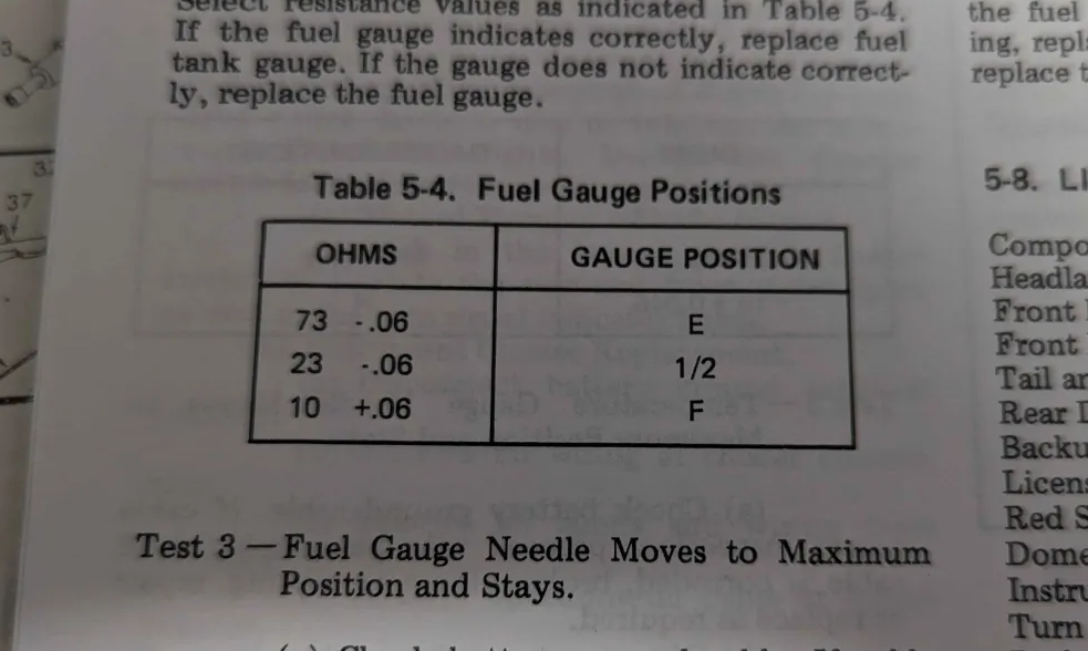
The factory service manual says the resistance values are for the gauge and sensor are:
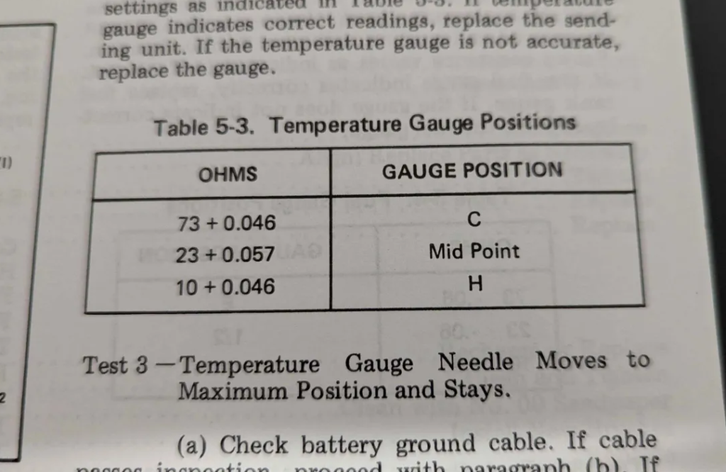
Cold engine is supposed to be around 73 ohms off the sensor, 23 ohms for operating temp, and 10 ohms for hot.
I taped a thermocouple to the sensor body and measured the resistance of the thermistor sensor.
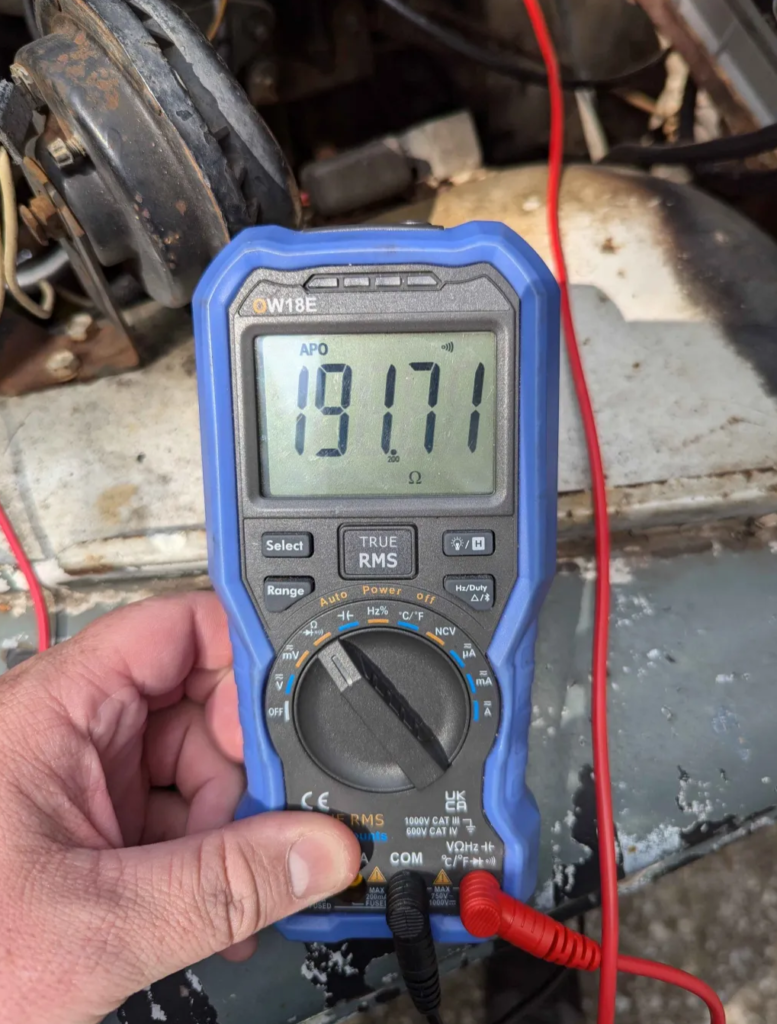
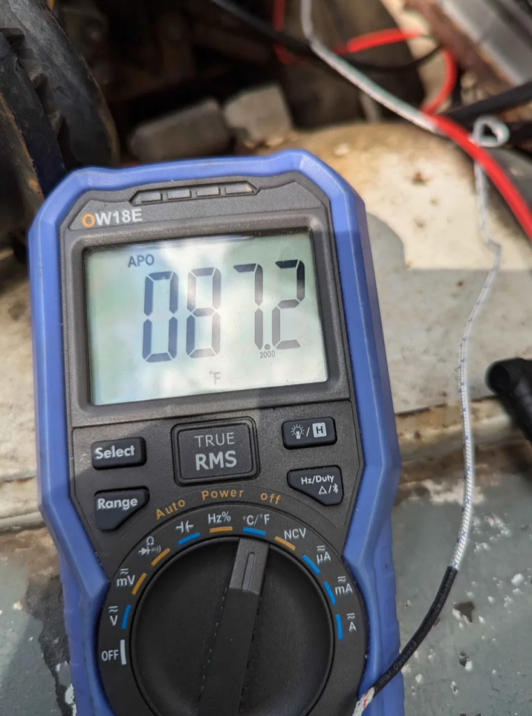
At ~87F the sensor is measuring ~192 ohms. That is way to high! But lets heat up the engine and see what we get.
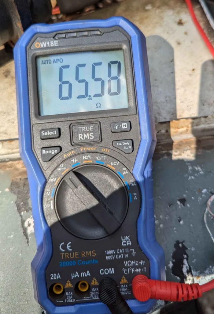
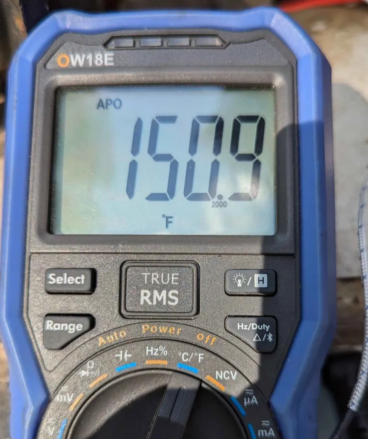
With the engine heated up to 151F the sensor is reading 66ohms. This is barely off the “Cold” mark the service manual says.
To test the gauge. I got a 22 ohm resistor and a 10 ohm resistor and “simulated” the sensor with them. These resistors moved the gauge to the appropriate spots! So the gauge is working correctly.
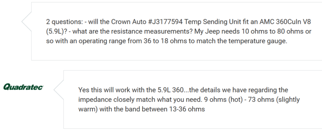
Finding a sender/sensor that works for this seems to be tough. Jeep used a couple different sensors and gauge combos over the years. According to Quadratec customer service, Crown’s J3177594 has the correct range.
I got this part on order and lets see if it works!
Keychain – MAILBOX
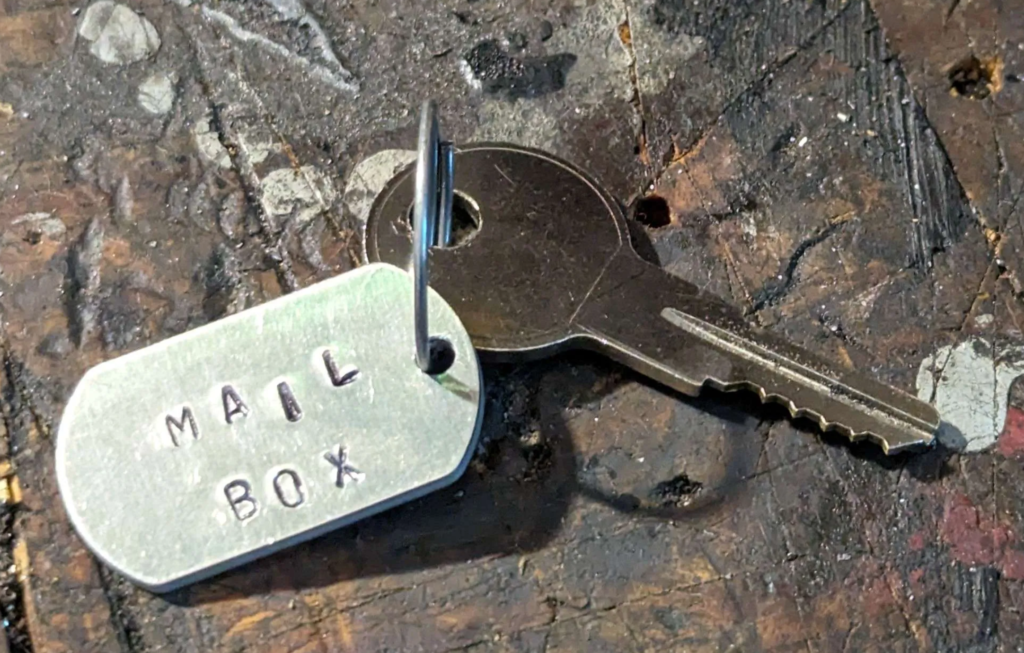
Keeping with the theme of the DJ Mail Jeep, I made a keychain by hand stamping a metal tag and then dry brushing the lettering.
Oh and the DJ has a nick name now. Mail Box!
New Tires and Wheels
The Jeep needed new tires bad. The ones it came with where dry rotted, leaked, and even one exploded on the previous owner with it just sitting in there driveway!
What to get? Well I want to keep the look of the Jeep as stockish as I can for the wheels and tires. These Jeeps had really thin tires and wheels.
Here is what the factory service manual said the Jeep came with. Tire size is E78 x 15 and Wheels are a 15″ 5.5″ K.
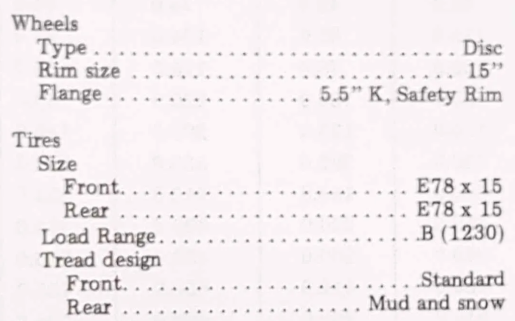
Well these are not modern sizes at all! But this makes sense. These jeeps came with bias ply tires with tubes.
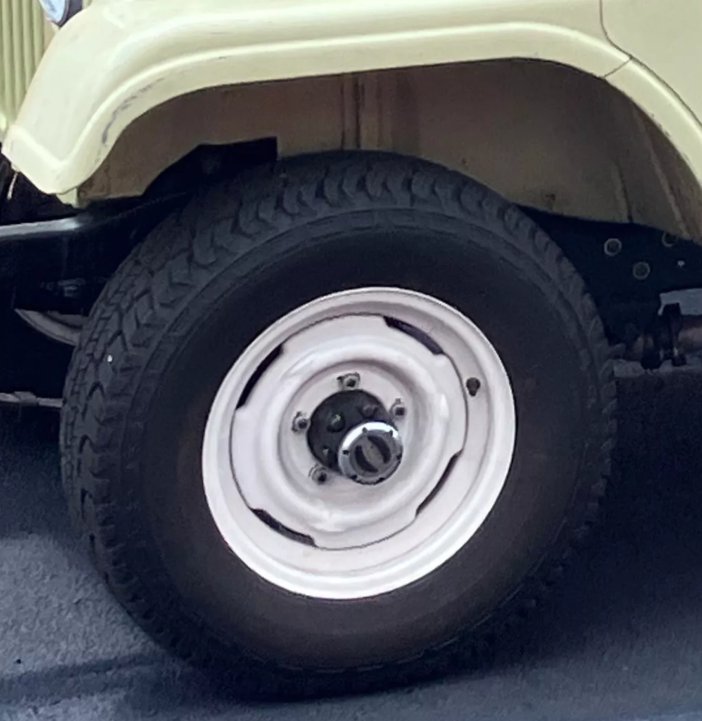
Lets try to find new wheels first. The bolt pattern on these Jeeps are 5.5″ x 5 pattern with a 4.25″ center bore. Common CJ Jeep pattern so that is good. Width is 5.5″ and 15″ diameter. The wheels the Jeep came with fit the Jeep but are actually 6″ wide. I know its only 0.5″ but i want to keep it skinny wheeled. I also don’t know what “K type” is as well? I have found some links on some old forums about the different type of wheels Jeep had but the link was dead.
I found this seller on Ebay that has original reproduction wheels for CJs that are 5.5″ wide and are for tubeless tires. Perfect!
Now on to the tires. E78 x 15 is an old school bias ply tire size.
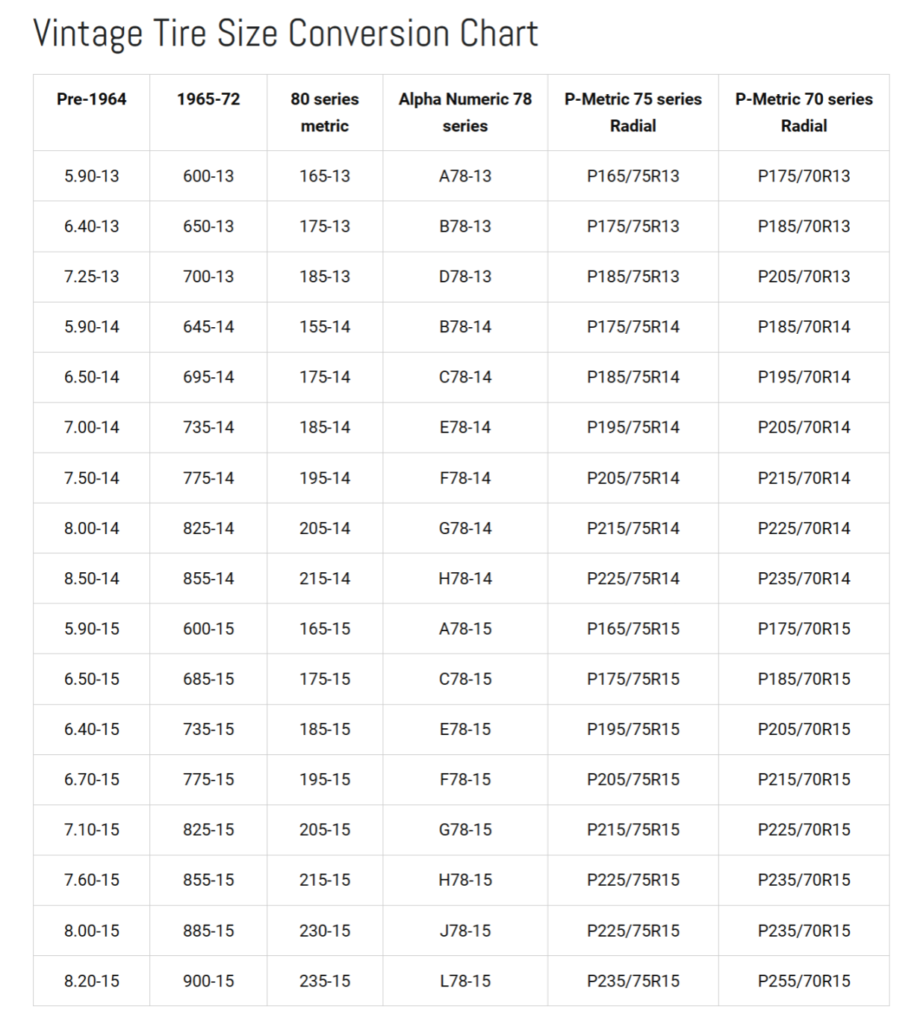
This chart says the tire should be around a 6.4″ wide tire. Modern size says P205/70R15.
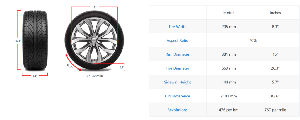
The modern tire is ~27″ diameter and ~8″ wide. That is way to wide! No wonder the turn stops on this jeep where jacked way out. The wider modern tires where rubbing at full steering lock.
I looked at some CJ-5 forums for tire sizes and found that 7.00-15 bias ply tires fit well and look the part. I found a set of Power King Extra Traction – Lt7.00x-15 on ebay.
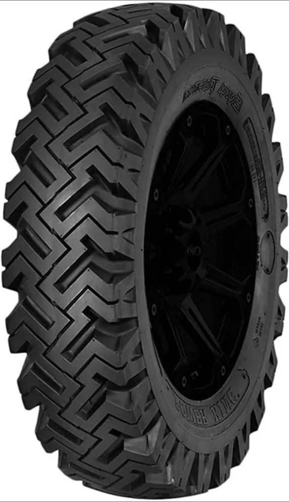
These tires are a bit taller then the stock ones that came on the DJ Jeep but atleast they are near the same width and look the part.
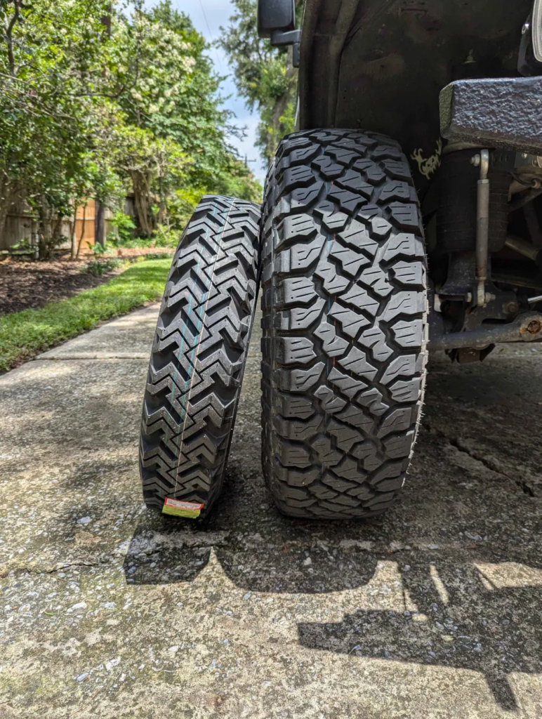
Here is how these 7.00-15 bias ply tires stack up next to my TJ Jeep’s 35″ x 10.5″ tires.
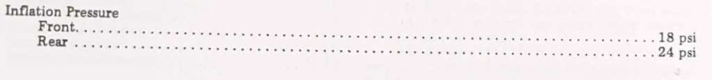
After mounting the tires and setting the pressure in the tires. 18psi in the front and 24psi in the rear.
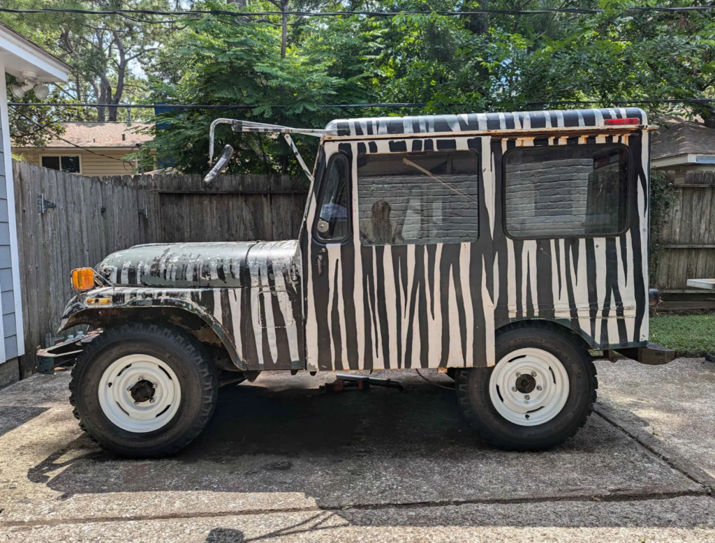
Tires and wheels look great on the DJ!
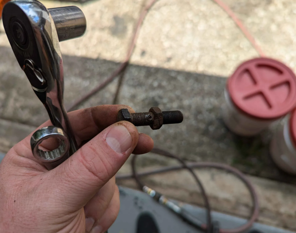
With the proper width of the tires, I adjusted the steering stops as far inwards as I could. Sometime in this Jeep’s previous life, someone welded the adjuster nut to the bolt so I could only adjust it so far. These are 3/8-24 fine thread bolts so next time I am at the hardware store I will pick up some so I can gain even more turning radius.
Fuel Tank Adventure
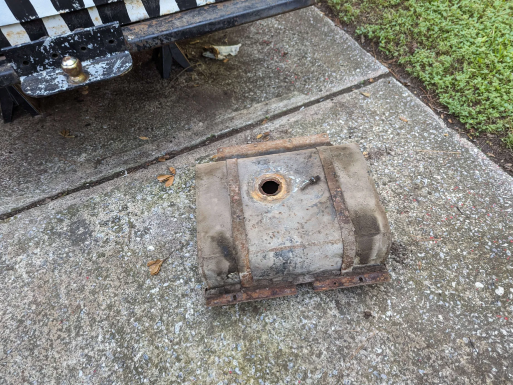
The previous owner of the DJ jeep mentioned that water kept getting into the fuel tank. This will be fun to get working. A flat blade screwdriver and a hammer tapping on the fuel sender locking ring and we can get a look inside.
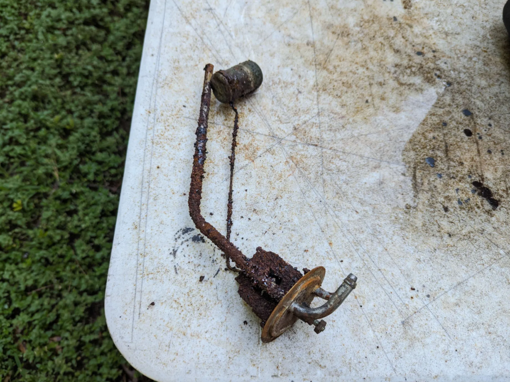
This fuel sender looks like it was on the Titanic.
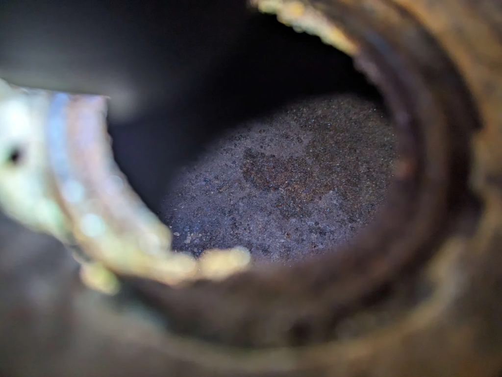
That is a lot of rust inside the tank :(
The tank dropped out with the removable of 6 bolts and tons of dirt and rust.
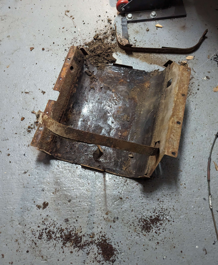
I took the fuel tank straps off and pulled the tank off the skid… The skid has traces of old gas and varnish on it… Not a good sign for the integrity of the tank.
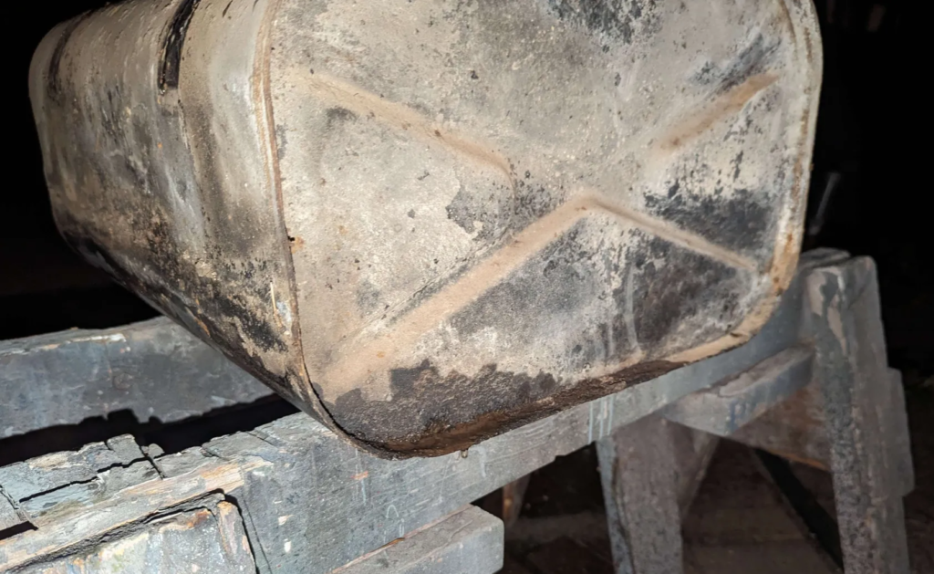
Filling the tank with water confirms my fears. The tank leaks.
I could try repairing the tank by removing all the rust and applying a liner but I think I am going to change to a CJ-5 Jeep Tank. Some searching online shows this won’t be a direct swap but it I should be able to make it work.
I ordered the following:
- MTS Company 0051 Fuel Tank
- Fits the 1978-1986 CJ Jeeps
- This is a plastic tank that fits CJ-5 and CJ-7 Jeeps
- Omix-Ada 17724.09 Fuel Pickup and Sender
- OE Reference: 5357373K
- Crown Automotive J5357023 Fuel Tank Skid
- My original skid does not fit the CJ-5/7 plastic tanks
- Spectra Premium ST60 Fuel Tank Straps
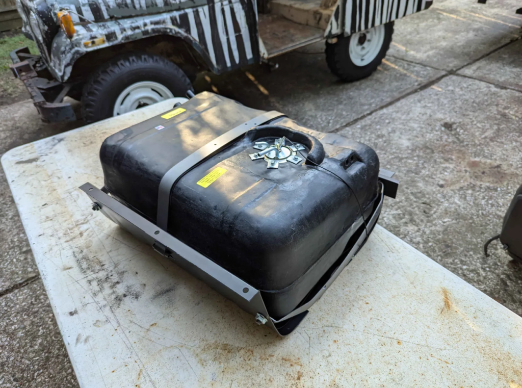
Tank assembled with the new sending unit, tank straps, and skid. I added some 1/16″ thick rubber between where the metal contacted the plastic tank.
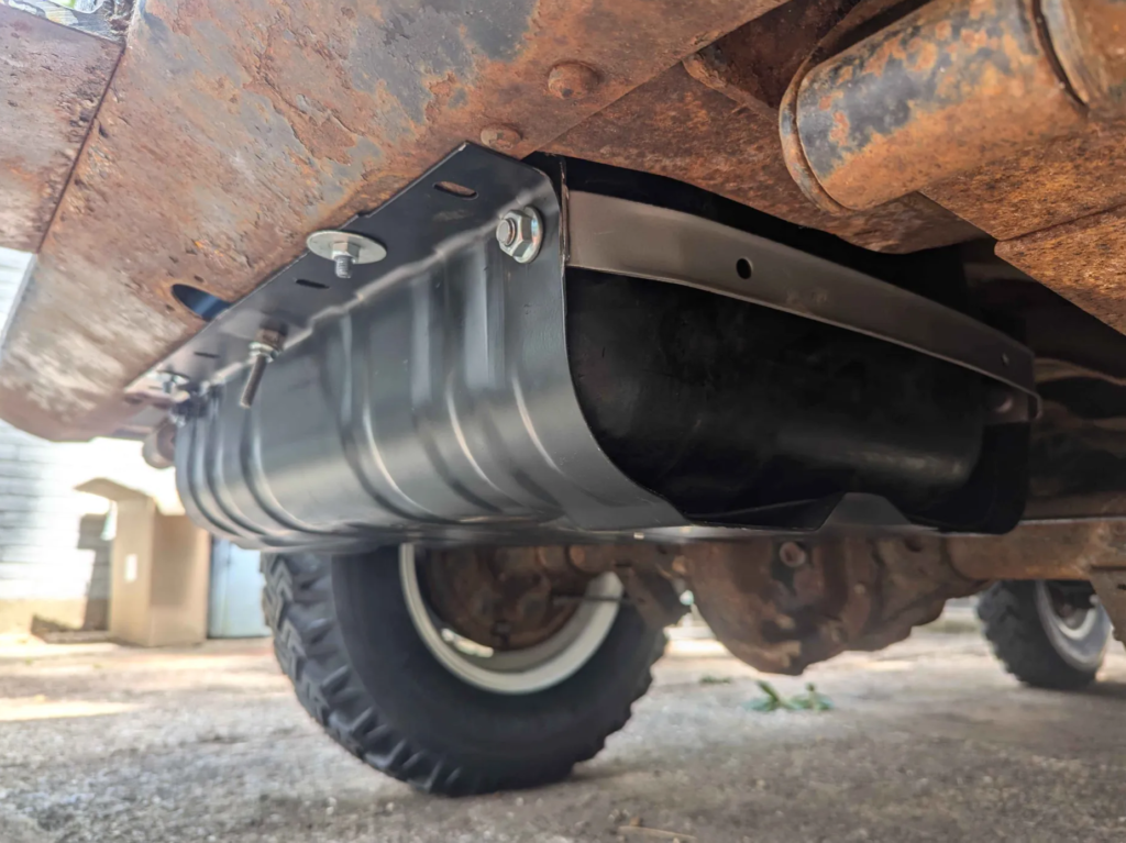
The skid needed some trimming and holes drilled to make it fit the DJ frame and cross members. The tank and straps did not need to be modified.
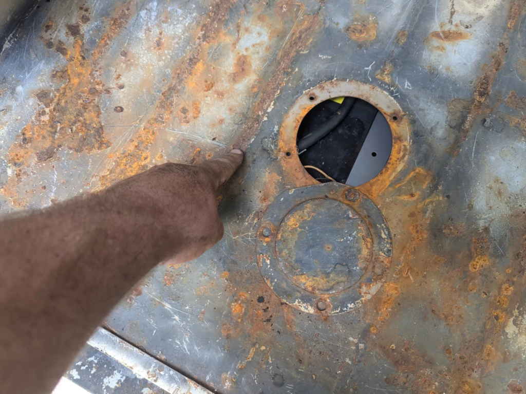
One of the problems with this tank is that it moves the sending unit. Not a problem for the wiring and fuel hoses but the access panel for the sender doesn’t line up anymore. Not a problem for a angle grinder though.
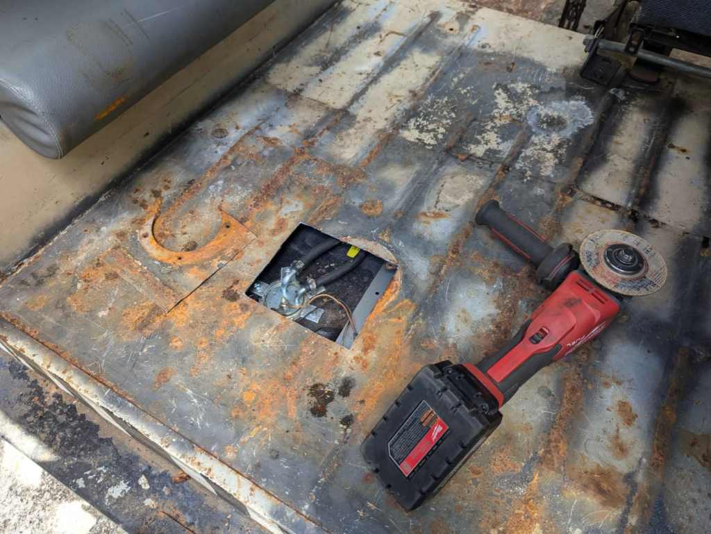
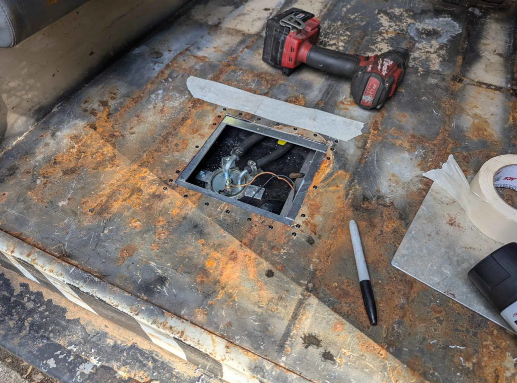
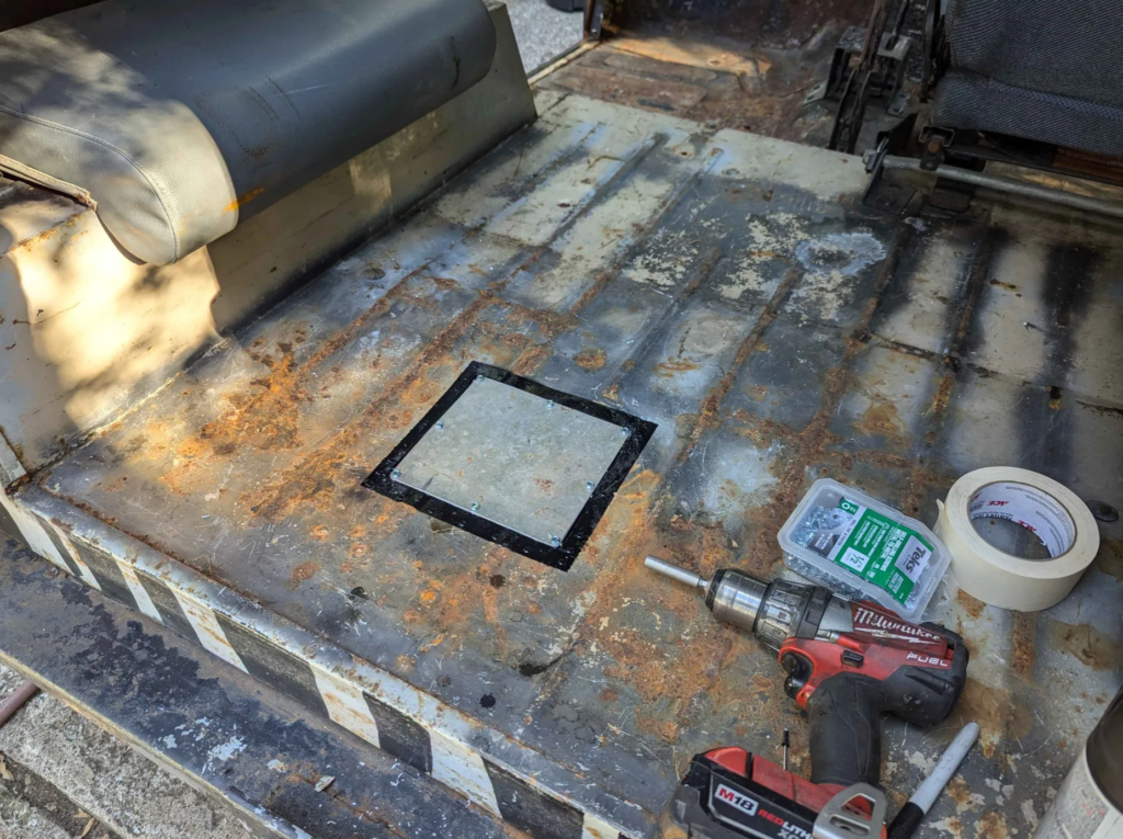
I cut the access panel large enough to access the new location of the sending unit and then riveted in some aluminum strips so I could screw down an aluminum plate to cover the hole.
Still need to see why the fuel gauge doesn’t work but the sender works and the tank hooks up to the stock filler hoses for this 1979 DJ.

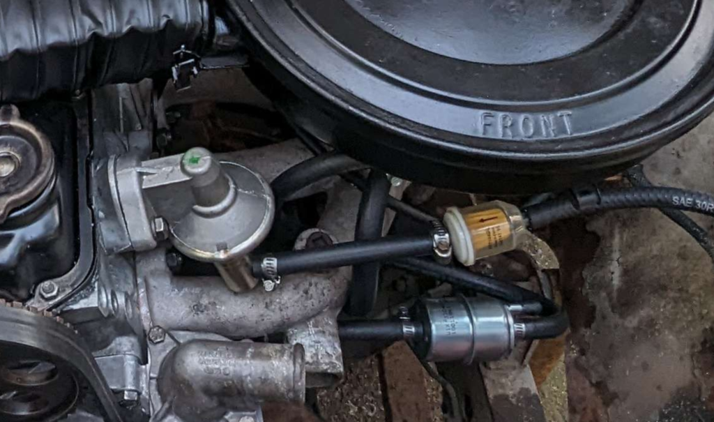
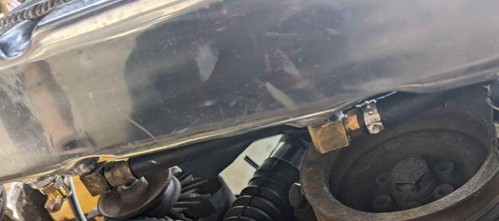
Here is how the fuel lines are routed up to the engine. The fuel comes from the tank in a 5/16″ line into a clear fuel filter. This goes into the intake side of the mechanical fuel pump. From the fuel pump it goes into another metal fuel filter. This fuel filter has a bypass line that has a restrictor inside. Bypass line is 1/4″ diameter and the smaller of the two barbs on the fuel filter. This goes back to the fuel tank. The other outlet of the fuel filter is 5/16″ and goes to the carburetor. The bypass line keeps fuel pressure down when the bowl float valve closes and allows the fuel pump to keep fuel moving in the lines to prevent vapor locking… in theory at least :)
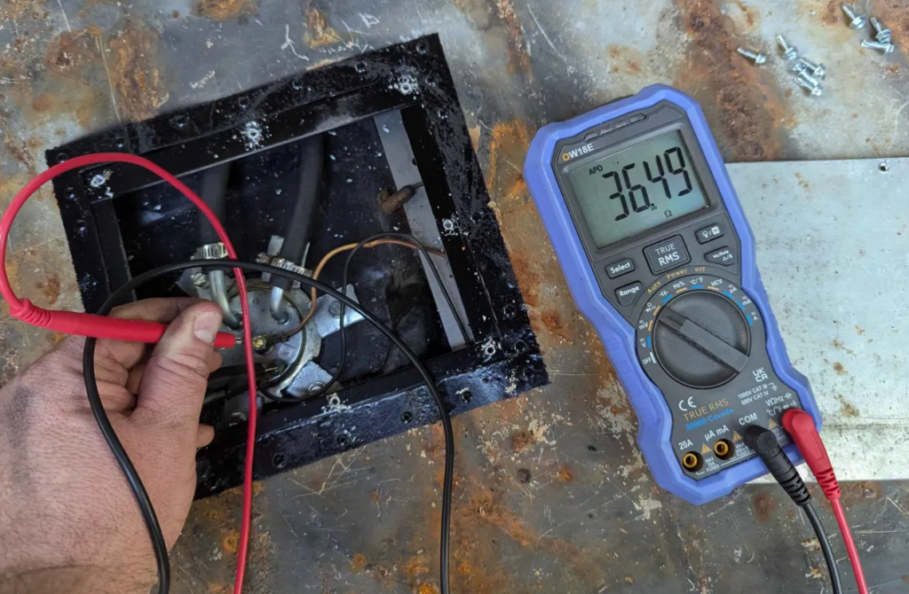
Now lets see if the new fuel sender works with the old crusty fuel gauge.
With some fuel in the tank we are getting 36 ohms. So we might be good!
The gauge didn’t work but taking apart and cleaning the gauge cluster got it to work correctly.

Contact cleaner and some adjustment and we have a working fuel gauge and tank!
Fixing The Headlights and Other Electrical
Almost all the electrical on the dash didn’t work besides the ignition switch. Over time stuff started to start working which lead me to believe that most of problems was due to connection and corrosion problems.
The Jeep came with a headlight switch so that was the first thing I replaced. This got the gauge lights and other interior lights working but the headlights didn’t work still. The wire from the headlight switch that goes to the headlights bulbs has 12V so the new headlight switch is working correctly.
Looking at the wiring diagram for the DJ Jeep, the power from the headlight switch goes to the hi/low beam switch on the floor. Poking at the hi/low beam switch with a multimeter showed that 12V was getting to the switch but not coming out. Time to see what is up.
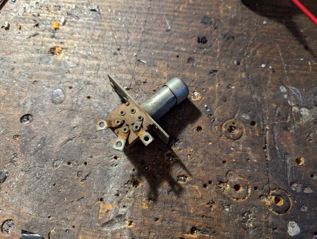
Here is the switch, doing a continuity test shows that no current is passing through. Opening up the switch shows it looks ok.
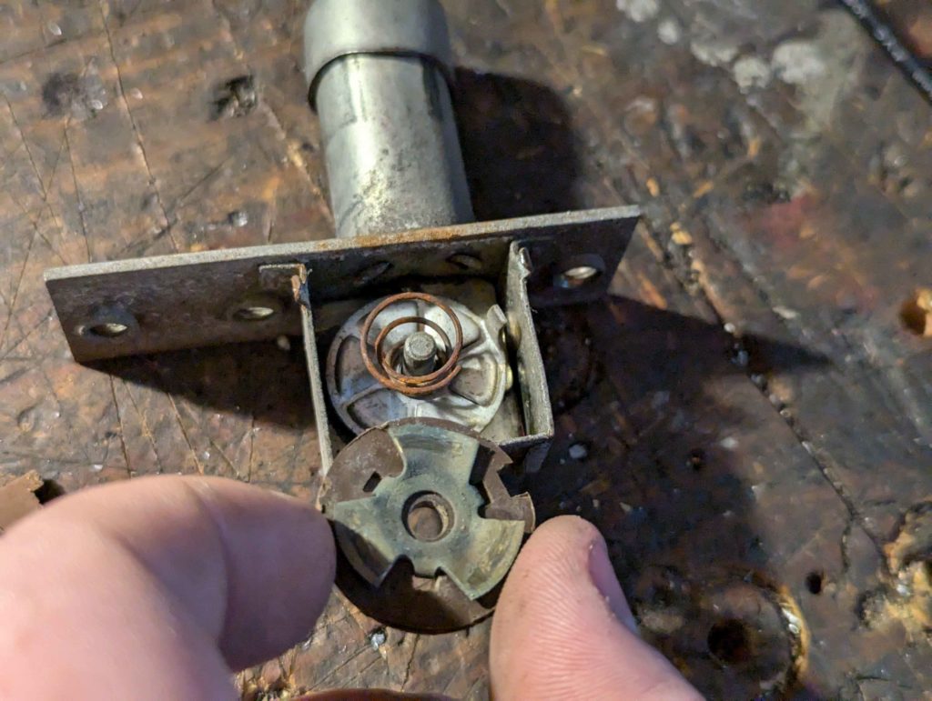
I cleaned the internal contacts with some contact cleaner anyways and reassembled. Switch still did not work. What I can figure, is that the pressed rivets that hold the contacts on have corrosion. I soldered the rivets together like this.
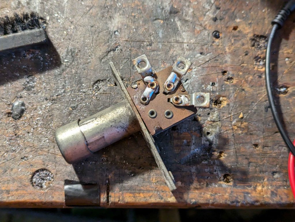
Which fixed the switch. This is the same switch used on the CJ jeeps so if this fails again I can just get a replacement.
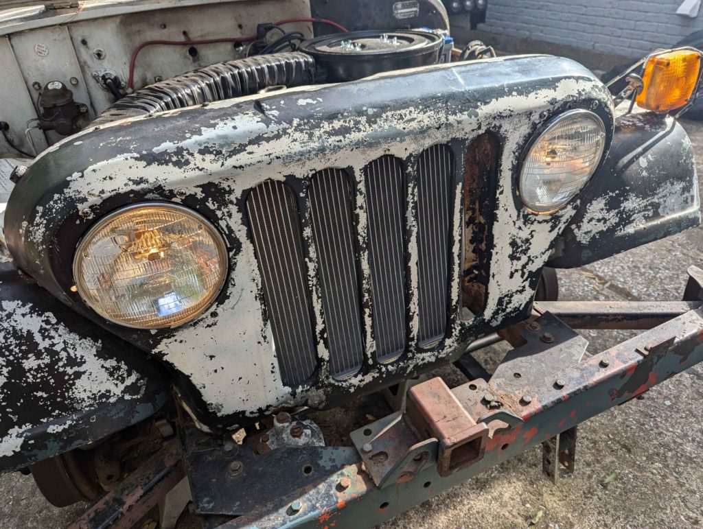
Headlights work! The gauges on the dash work but there is clearly a problem with the grounding or power to the gauges as they are not correctly reading. I will try replacing the ground strap from the engine to frame and add one from the frame to the dash like modern Jeeps have.
Fixing The Suspension
The DJ Jeep came with a set of new in box shocks. The ones on the Jeep where out of gas. I dunno how long these old new in box shocks will last but they are at least working for now.
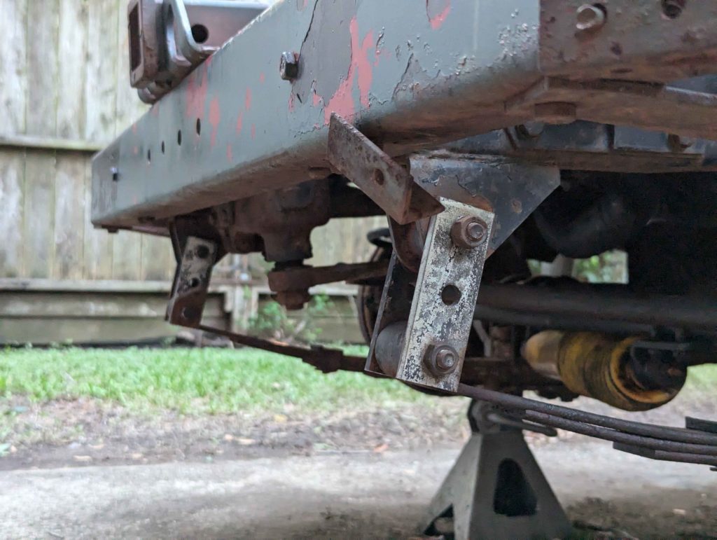
What is weird about the suspension is that the front shackles have been replaced at one point with lifting shackles.

The previous owner mentioned that this Jeep was once used as a boat ramp launching vehicle and suspected that these longer shackles where installed to prevent the suspension from bottoming out.
I dunno if this is true about the DJ Jeeps but every Jeep I have worked on, the front and rear shackles for the leaf springs are the same length.
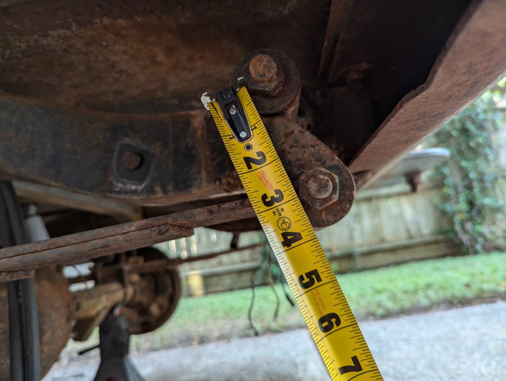
Rear shackle measures 3″ from bolt to bolt.
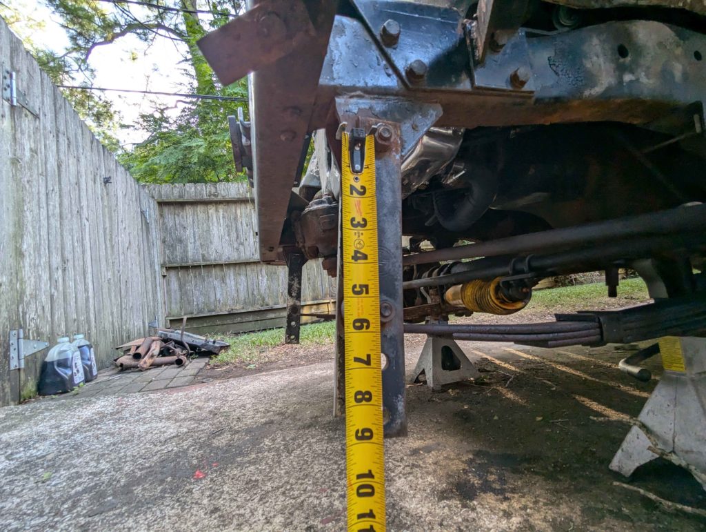
Here are the lift shackles. 5.5″ for a 2.5″ lift in the front. What is interesting is the bottom holes for adjustment.
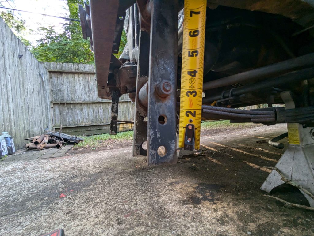
The holes are 1.5″ spaced so I can cut these long shackles down and make a normal 3″ long pair.
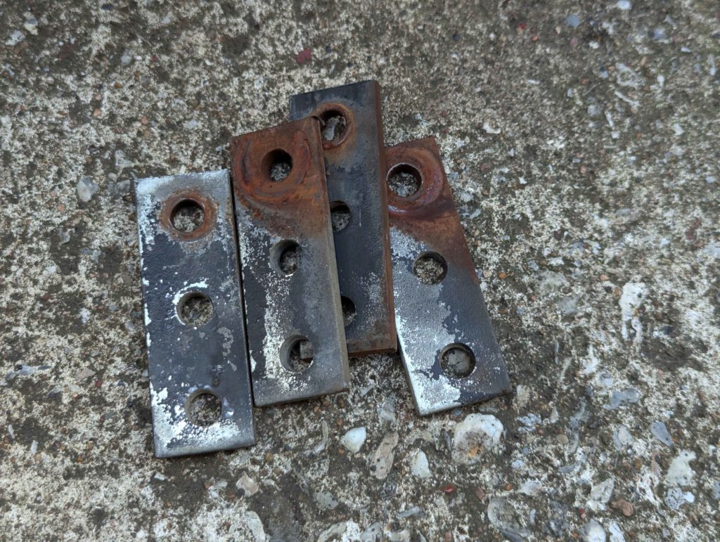
Just that easy!
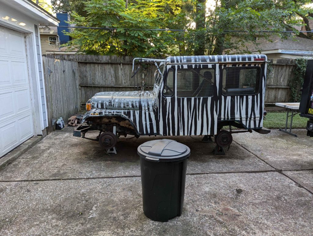
No more Carolina Squat for this Jeep.
Getting The Brakes To Work
The DJ Jeep is a 4 drum, manual braking system. Very basic but it works well and with only 100 HP and 2200lbs of curb weight, the drum system will work fine. We are just going to rebuild what is there.
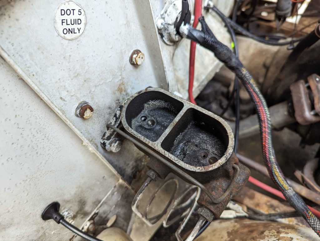
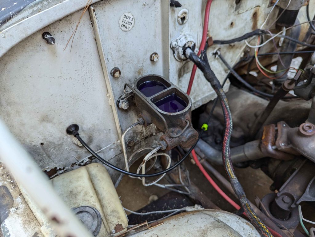
DOT 5! Interesting. DOT 5 is a silicon based fluid instead of the typical glycol based DOT 3, 4, 5.1 stuff. It has some interesting advantages over the glycol based fluid. DOT 5 does not absorb water like glycol based fluids, thus brake systems don’t rust out. Downsides are that it can’t be used in ABS systems. Both are not compatible with each other so we should stick with DOT 5. Maybe future car builds I should switch to DOT 5… I mean look at that master cylinder, just some dried out silicon fluid, no rust!
I cleaned out the master cylinder with some denatured alcohol and then flushed the entire system with the denatured alcohol. This gets rid of any residue and water that may be in the lines. I then took all the soft brake lines out and used compressed air to blow out the rest of the alcohol.
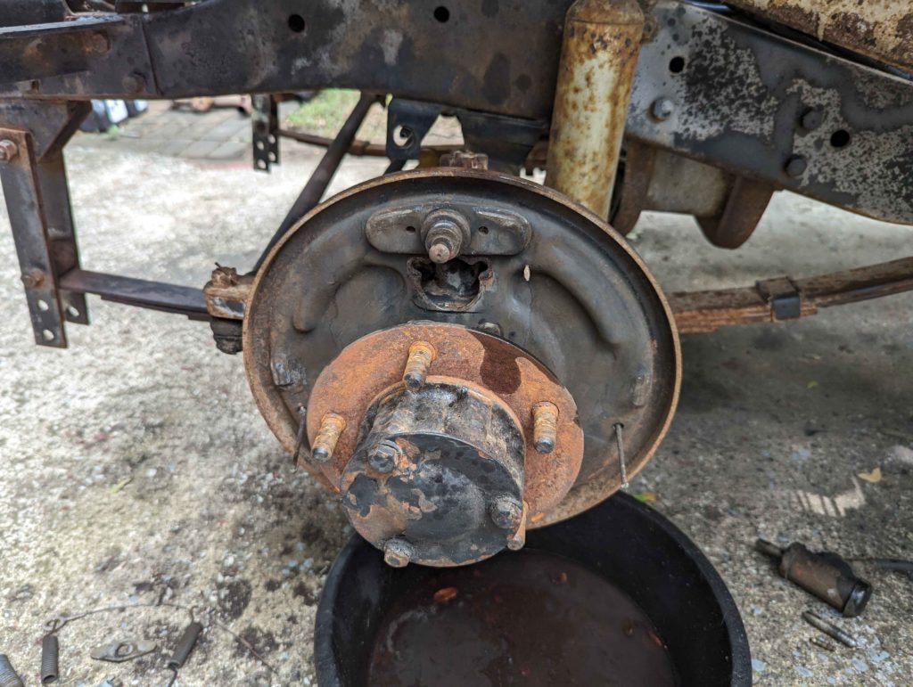
I then popped the drums off the brakes with a drum puller. Highly recommend getting a drum puller like an Astro 78830.
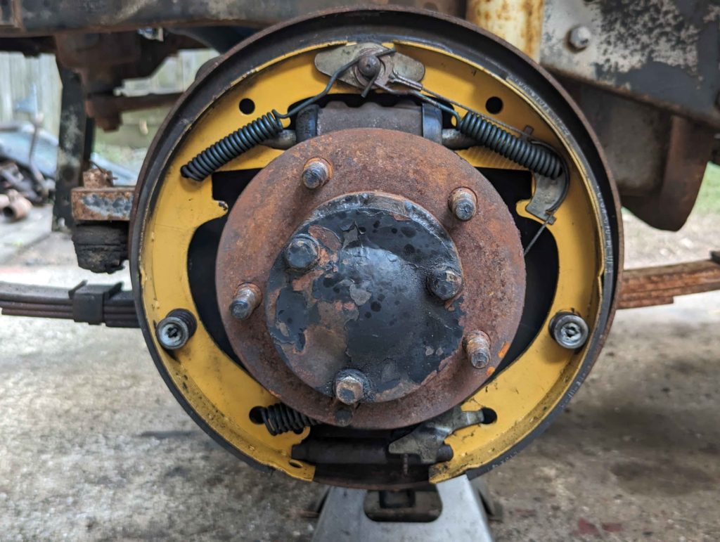
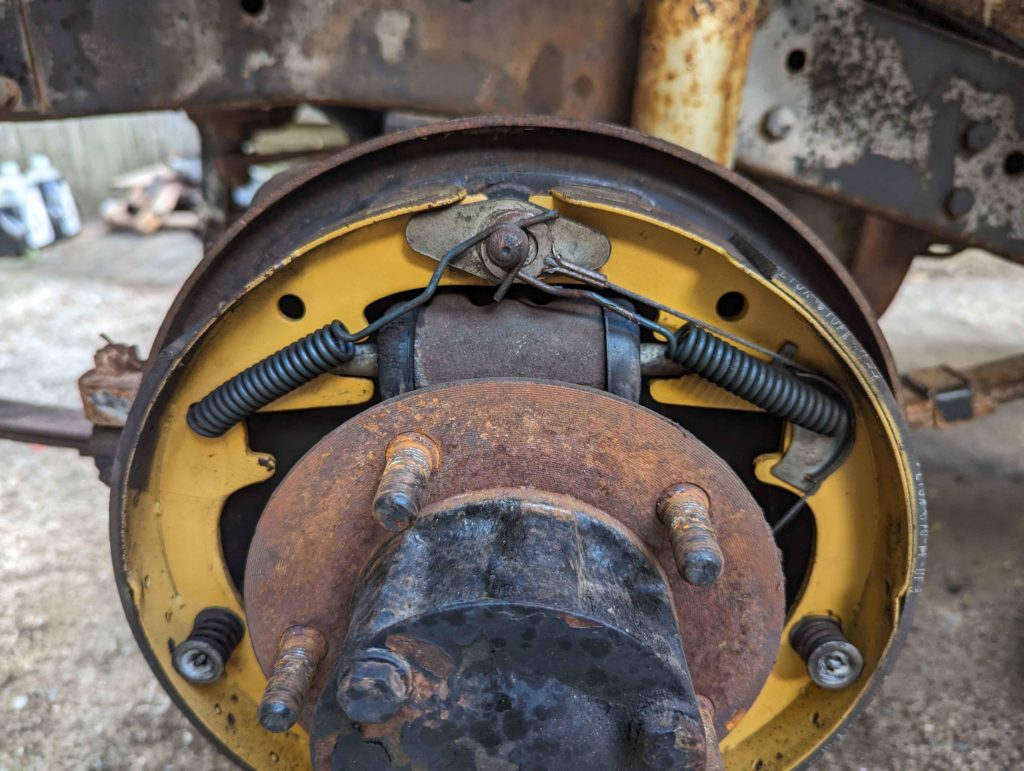
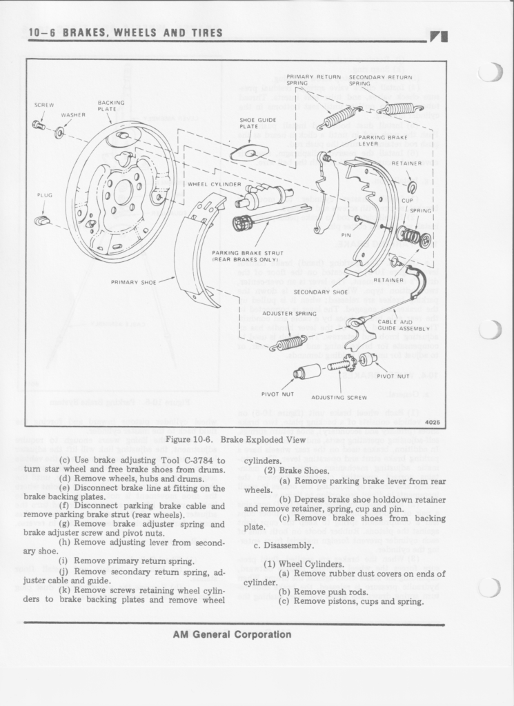
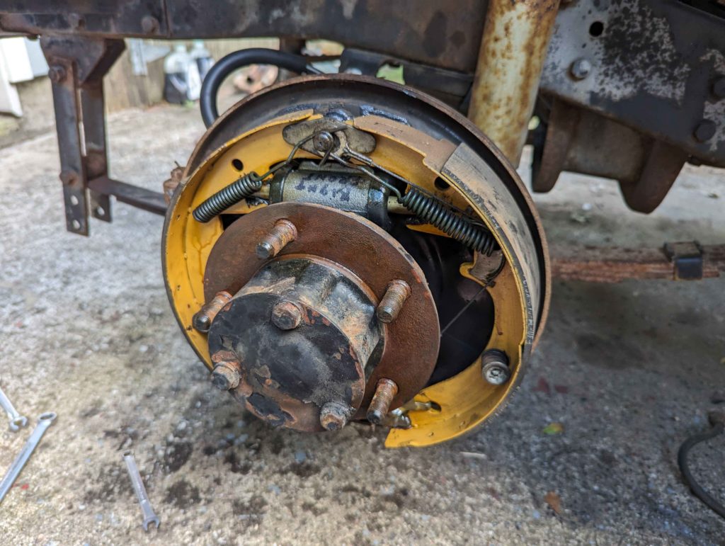
This is what the brakes look like before disassembly. Make sure to take pictures!
To easily remove the springs get a Lisle 44800 Heavy-Duty Brake Spring Tool.
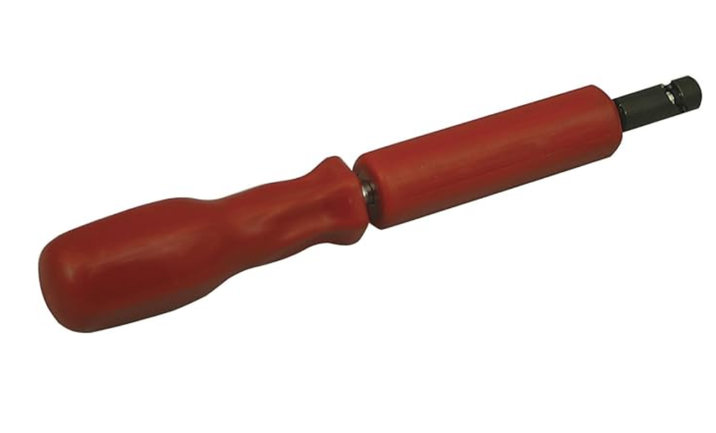
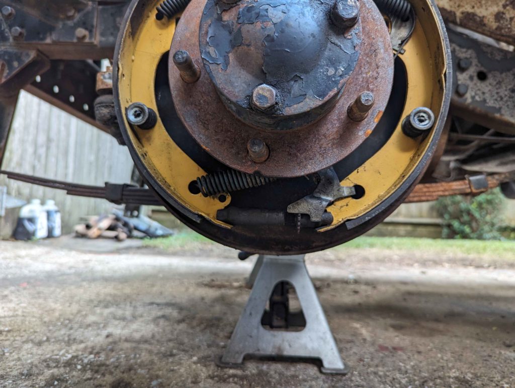
It screws onto the springs and grips them. I find it easier to remove the bottom spring first and then the top 2 springs on drums. After disassembly, clean all the parts with brake clean. Replace the drum cylinder with a new one and install a new rubber line. On all the surfaces where metal rubs on metal, apply some brake grease, don’t need a lot.
Reassembly is reverse of how it came apart. Make sure that self adjusting cable goes on correctly. Put the top two springs on before the bottom spring seemed to be the easiest way.
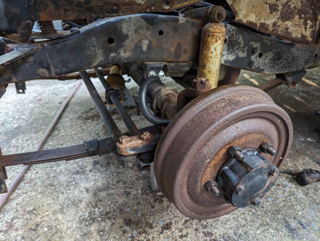
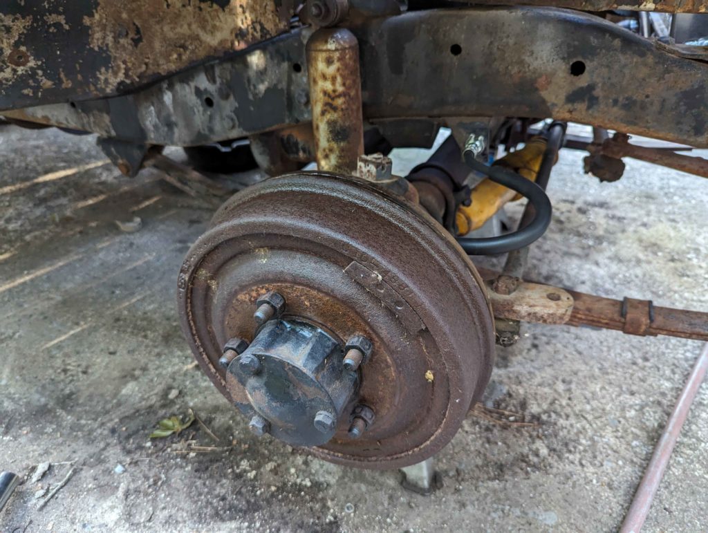
The outside of the drums I hit with a wire brush to knock off surface rust and then hit them with an anti corrosion spray. It will eventually bake off but atleast keeps them from rusting more for now. I want to eventually paint these drums.
Then fill and bleed the system with fresh DOT 5. This DOT 5 fluid had a dye in it so it was easy to know that the rest of the alcohol was flushed out when the purple DOT 5 fluid showed up in the vacuum bleeder.
Brakes tested and they work!
Replacing The Throttle Cable
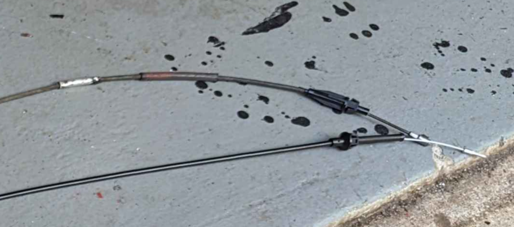
The throttle cable on the DJ was previously damaged and been repaired a couple times. This is causing the cable to grab and not allow the carburetor to close.
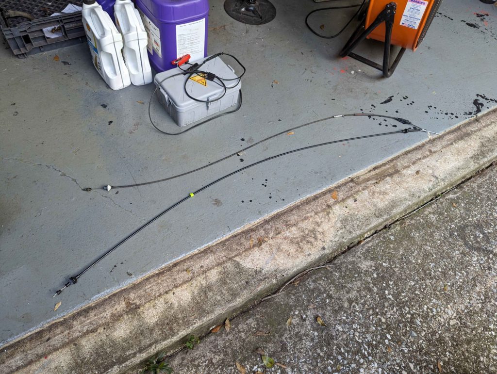
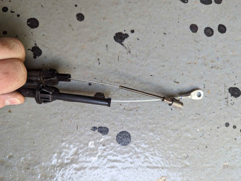
The replacement cable I was able to find was close in length but needed a different end for the carburetor.
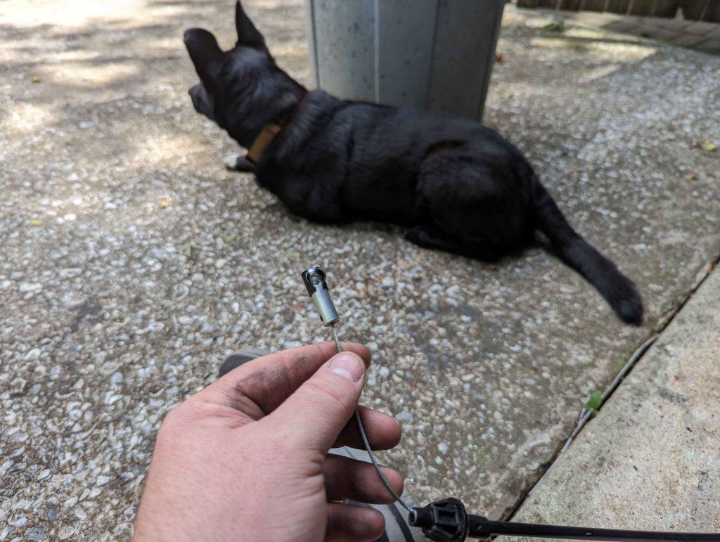
Cut off the original end and put on this ball end for the cable. This just clips onto the carburetor.
Transmission Cooler Lines and Oil Pressure
Since I replaced the radiator, the transmission cooler lines needed to be removed. I dunked these in the ultrasonic cleaner to get the grunge off.
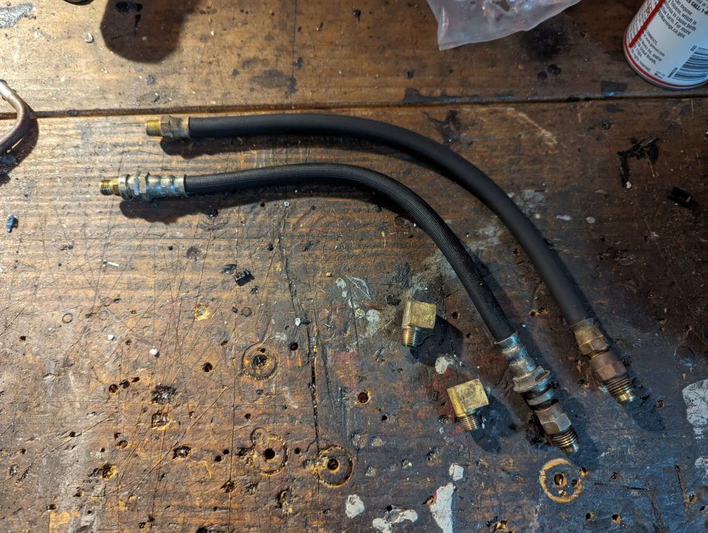
One of these lines is not like the other! A line was made from a converted brake line. The rubber of that hose was all gummy and starting to fall apart. I ended up replacing it with some barb fittings and a piece of transmission cooler hose.
I noticed while running the engine, that the oil pressure gauge never seemed to move once running. It was sitting at ~30-40lbs of pressure. I read on Porsche 924 forums that the oil pressure of these engines is supposed to be high. Looking in the service manual we have.
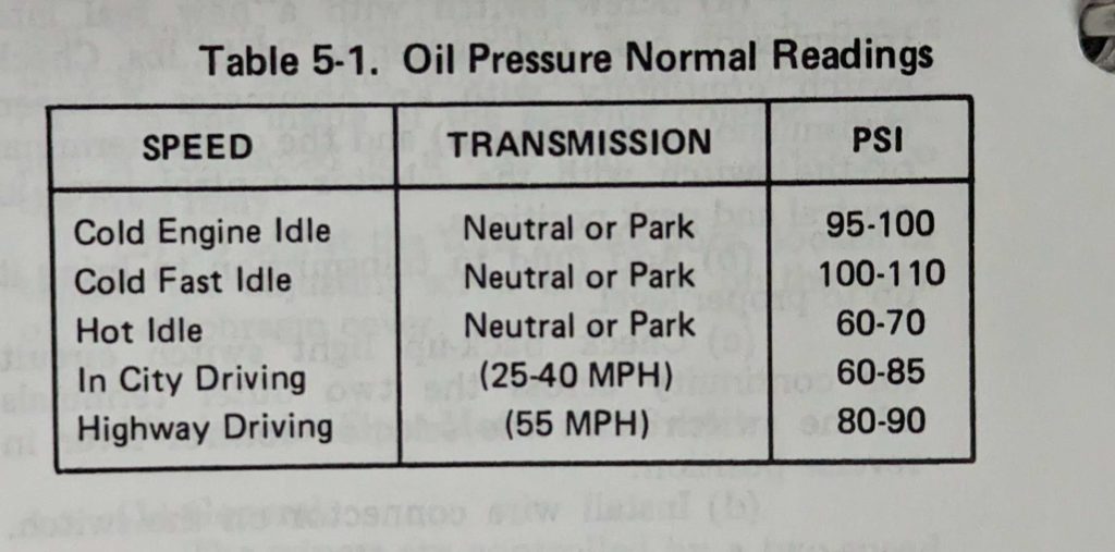
Cold idle should be around 100 PSI! 30 is much too low. But before figuring out if there was an oil problem or bearing problem, lets just check the gauge and sender. The gauges on this jeep are old and probably way out of calibration.
Measuring the sensor off the back of the engine with a multimeter I was reading ~140ohms at cold idle. The service manual has a way to calibrate the oil pressure gauge and specifies two points.
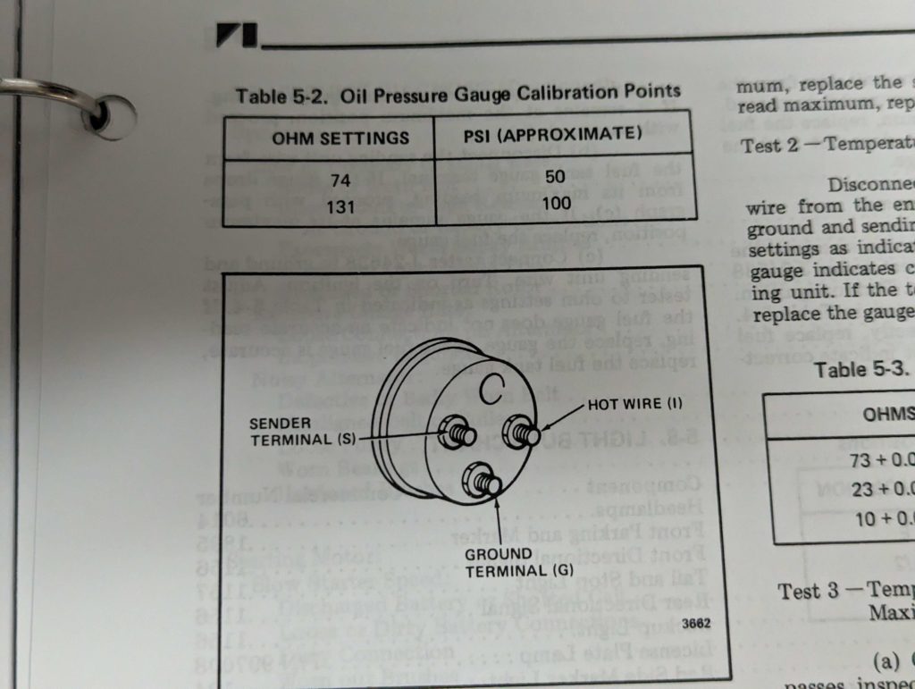
So 140ohms would be around 110psi. Looks like the engine is happy with oil pressure! Will have to figure out what is up with the gauges. I am betting that the ground for the dash has a bad connection.
It ended up just being some dirt in the gauge preventing the needle from moving.