Changing hosts….be back soon!
Raspberry Pi Laptop
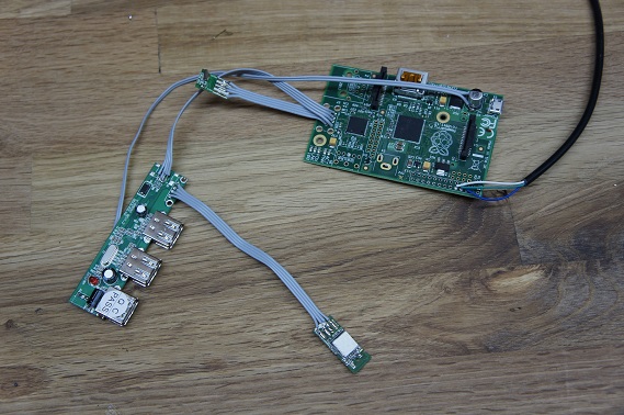
Working on a small Raspberry Pi Laptop. So far I have stripped the pi of all of its large connectors. I have the USB hub wired directly to the pads. The wifi adapter and dongle for the keyboard are also stripped of there case and soldered directly to the connections.
I have a 7″ screen I will be using for the display. Looking into HDMI switches so I can use an external display.
Prop Dev Stick REV 0B
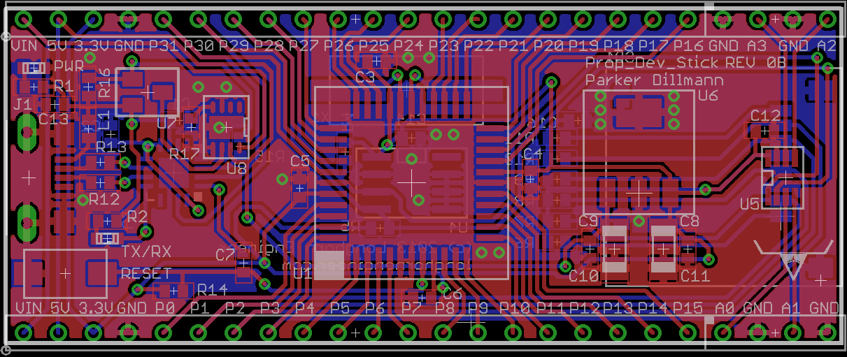
Finished REV 0B for the Prop Dev Stick. I minimized the size of the board from 1.5″ to 1″ wide. It is now thin enough to plug into a bread board. Width between the two rows of headers is 0.9″.
Some quick specs. Running the propeller at 96MHz, Micro SD card slot, 4 channel 8-bit ADC, built in USB, and all I/O brought out to the edge. A power MUX controls whether or not the Prop Dev Stick uses USB power or power from an external source like a battery. This way you can have the unit running off battery or solar and still use the USB connection for serial data. When an external power source is absent the mux switches over to USB power.
Prop Dev stick…a PCB?
In this case PCB stands for Phoenix Circuit Board. I have not worked on this project since September 2011.
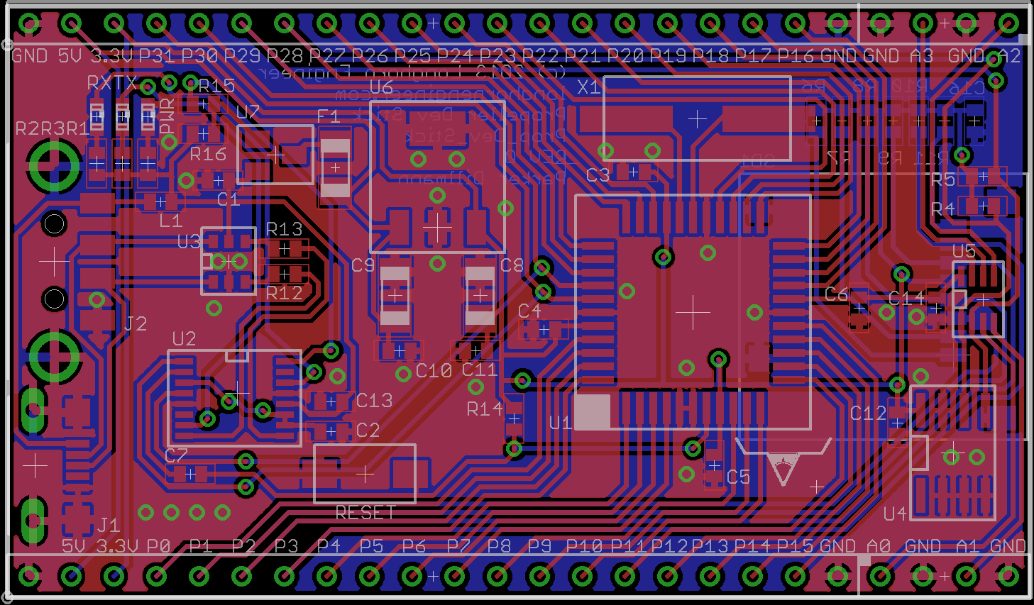
The Prop Dev Stick is a Parallax Propeller development platform that is designed to just plug into a computer like a USB thumb drive. The old design was just the Propeller MCU with no frills. This time around I added a micro SD card slot and a ADC for reading sensors.
ISR PWM Motor Control
This code runs the Low Voltage Motor Booster Pack for the MSP-430 with the MSP430G2553 chip but could easily be adapted to any microcontroller. This uses Timer1_A0 to make a timing interrupt. Using the timing interrupt it changes the duty cycle of the PWM. Supports reverse by sending the “move_motors” command negative values.
Default is P2.0, P2.1, P2.2, and P2.3 for controlling the motor driver. P1.0 is toggled (on board LED) in the ISR.
Code: CCS V5
isr_motor_pwm.c
isr_motor_pwm.h
Project File Ver1.0
/*
*isr_motor_pwm.c
*Version: 1.0
*Parker Dillmann
*The Longhorn Engineer (c) 2013
*www.longhornengineer.com
*
*Check bottom of file for License.
*
*/
#include "msp430g2553.h"
#include "isr_motor_pwm.h"
#define Motor_DIR P2DIR
#define Motor_OUT P2OUT
#define Motor_A1 BIT0
#define Motor_A2 BIT1
#define Motor_B1 BIT2
#define Motor_B2 BIT3
volatile int Motor_Speed_A;
volatile int Motor_Speed_B;
volatile int Motor_isr_cnt;
void init_motors(void)
{
TA1CCTL0 = CCIE; //Enable the CCR0 interrupt
TA1CCR0 = 50000; // Set the interrupt register to "trip" each 50000 cycles"
TA1CTL = TASSEL_2 + MC_2 + TACLR; //Timer_A Source Select; Set source to SMCLK, continuous mode, clear TAR
P1DIR |= 0x41; // P1.0 output
Motor_DIR |= (Motor_A1 | Motor_A2 | Motor_B1 | Motor_B2); //Set Motors to output
Motor_OUT &= ~(Motor_A1 | Motor_A2 | Motor_B1 | Motor_B2); //Set Motor outputs to 0
Motor_isr_cnt = 1;
return;
}
void move_motors(int Speed_A, int Speed_B)
{
Motor_Speed_A = Speed_A;
Motor_Speed_B = Speed_B;
return;
}
void stop_motors(void)
{
Motor_Speed_A = 0;
Motor_Speed_B = 0;
return;
}
#pragma vector = TIMER1_A0_VECTOR
__interrupt void Timer1_A0_ISR(void)
{
//Upkeep Time
Motor_isr_cnt++;
if (Motor_isr_cnt == 512)
{
Motor_isr_cnt = 1;
}
//Motor_A PWM
if (abs(Motor_Speed_A) >= Motor_isr_cnt)
{
if (Motor_Speed_A > 0)
{
Motor_OUT |= Motor_A1;
Motor_OUT &= ~(Motor_A2);
}
else
{
Motor_OUT |= Motor_A2;
Motor_OUT &= ~(Motor_A1);
}
}
else
{
Motor_OUT &= ~(Motor_A1 + Motor_A2);
}
//Motor_B PWM
if (abs(Motor_Speed_B) >= Motor_isr_cnt)
{
if (Motor_Speed_B > 0)
{
Motor_OUT |= Motor_B1;
Motor_OUT &= ~(Motor_B2);
}
else
{
Motor_OUT |= Motor_B2;
Motor_OUT &= ~(Motor_B1);
}
}
else
{
Motor_OUT &= ~(Motor_B1 + Motor_B2);
}
  P1OUT ^= 0x40;    // Toggle P1.0
TA1CCR0 += 500;  //Add offset to CCR0
}
DIY for the Homebrew Temperature Controller Uploaded!
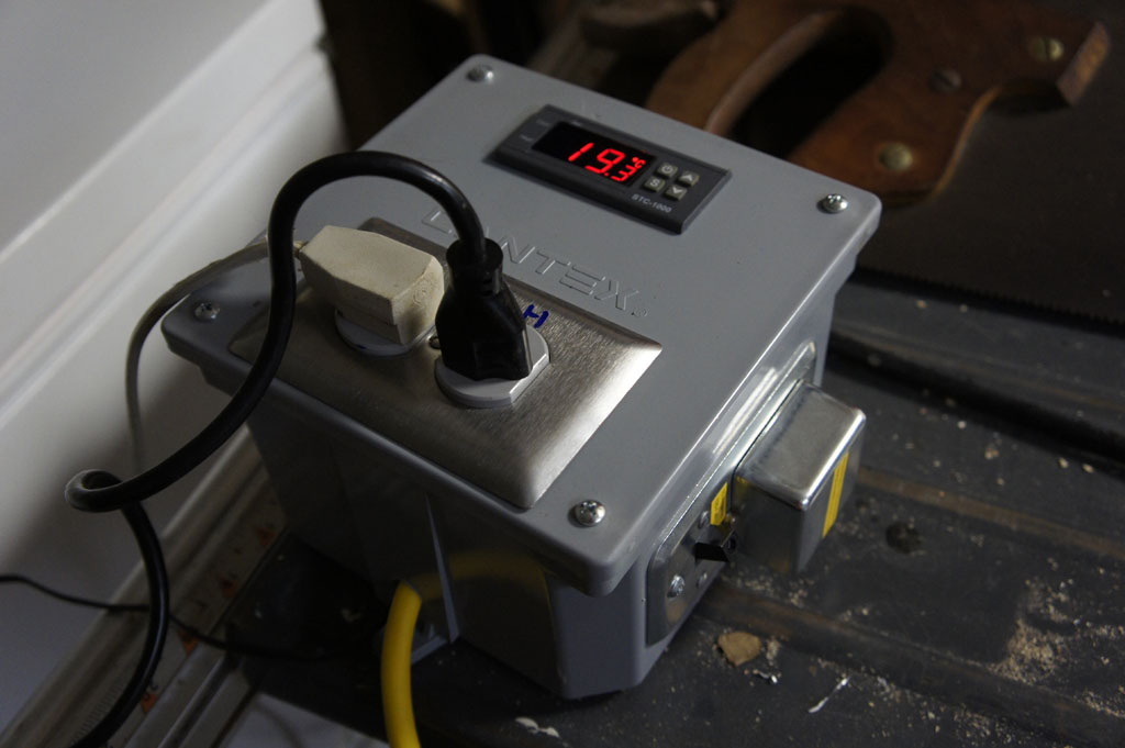
One of the best ways to improve your homebrew is to temperature control your fermentation. My setup for my fermentation container is a 15 sqft chest freezer with a 60 Watt space heater inside it. To control this I made a temperature controller which is detailed below.
Please read the Disclaimer before attempting.
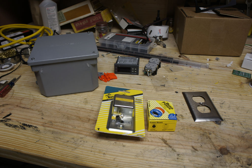
Part List:
Electrical Box – Any project box large enough will work. I am using an outdoor electrical box I found at Homedepot. Size is 8″x8″x7″.
Digital STC-1000 Temp Controller – Make sure to get the 120V one.
Electrical Socket – Get the cheapest one. Grab a face plate as well. Homedepot sourced.
14 AWG Extension Cord – This will be used to supply power to the unit and supply the wiring for inside the box. Homedepot sourced.
Bussmann Switch and Fuse Holder – Grab some 10 Amp fuses to. Homedepot sourced.
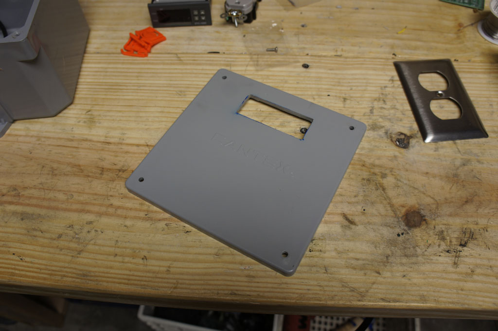
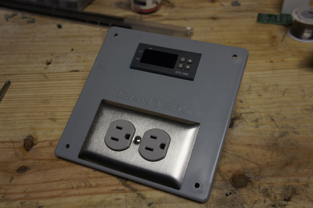
Cut a hole in the front panel using a Dremel like tool for the Temperature Controller. I just traced the profile of the controller.
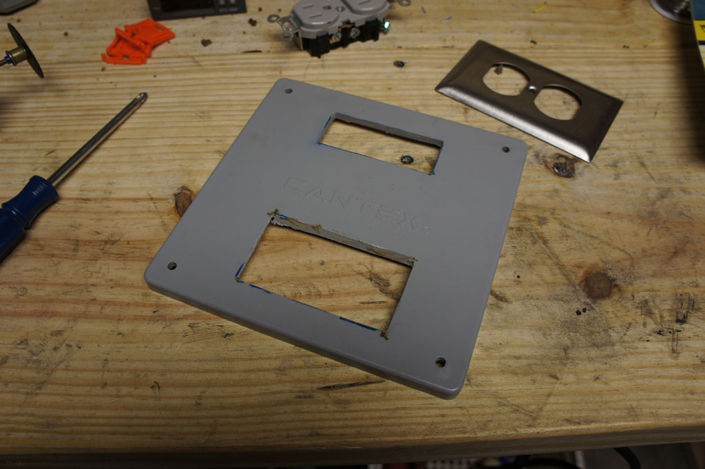
Below that cut the hole for the Electrical Socket. No need to cut it exactly the right size. The faceplate will go over this.
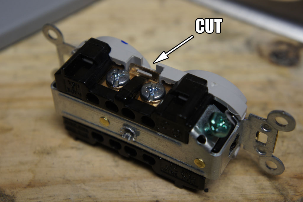
Using your Dremel again cut this tab all the way through. This disconnects the Live side (black wire) of the socket. This way one socket is for the heater and one is for the compressor (cooler).
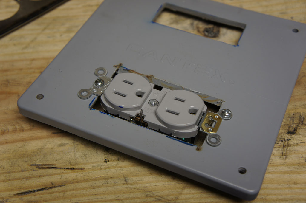
Screw in the socket.
Face plate and Temperature Controller inserted.
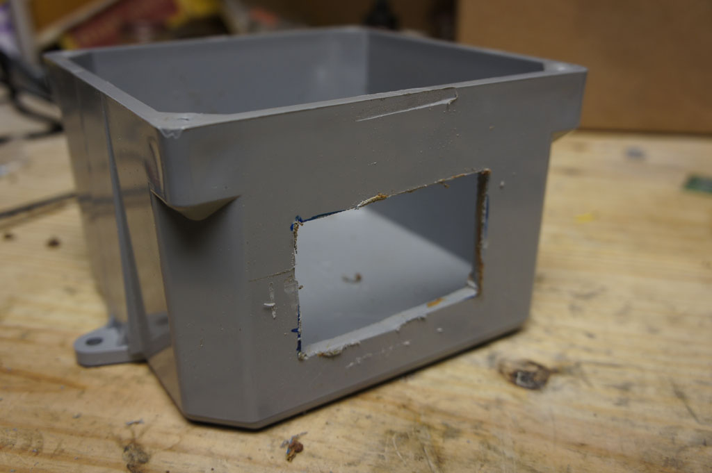
Cut a hole in the side for the Bussmann Switch and Fuse.
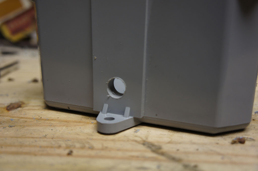
Drill a 1/2″ hole at the bottom. The power cord and temp sensor will come out of here.
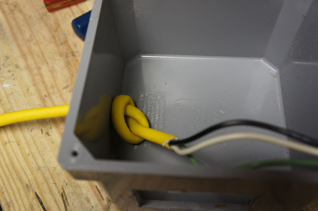
Cut the plug off the extension cord and strip about 1′ of insulation off. Feed the cord through the hole and tie it into a knot like above. This prevents the cord from being pulled out. Time to wire it up now.
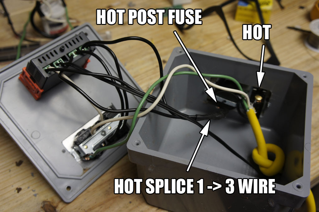
Complete overview of the wiring. Everything is color coded. Black is Hot, White is Neutral, Green is Ground. The only splicing you will need is on the Hot wire coming off the Bussmann. I soldered and heat shrinked this connection but you can just wire nut it.
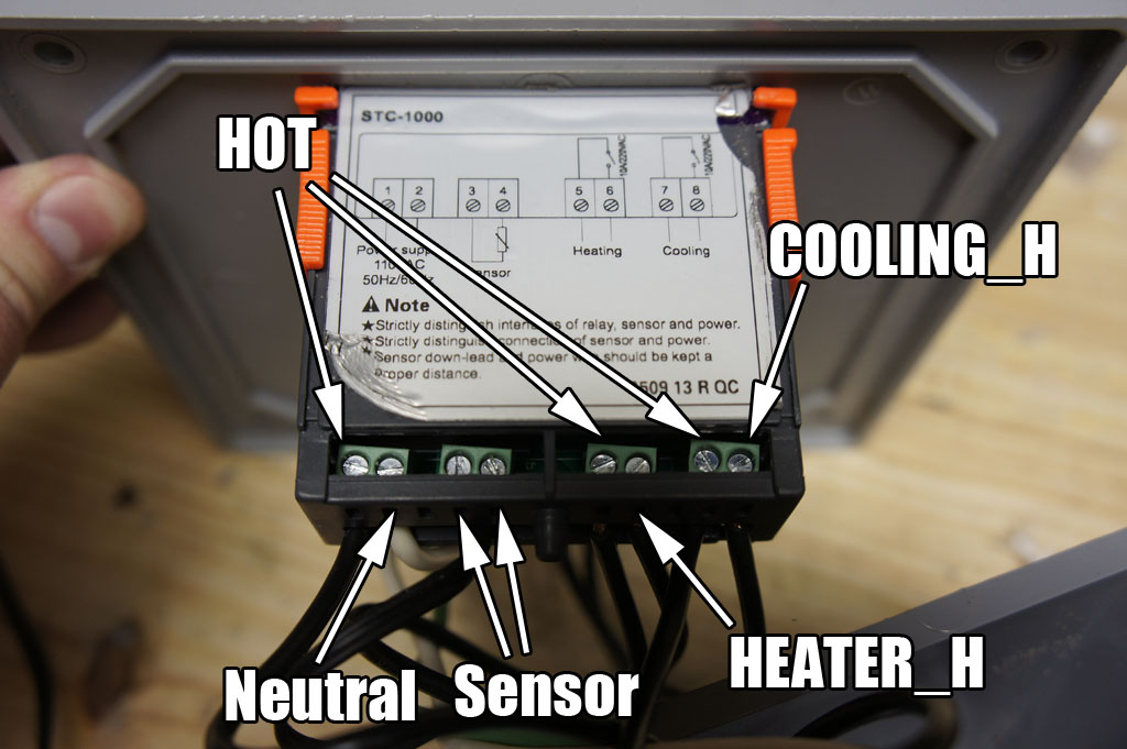
View of the back of the controller. The Hot locations come from the 1 to 3 splice that comes off the Bussmann fuse. Cooling_H and Heater_H are the Hot wires that go to the Electrical Socket. The Sensor wire gets wired in as well.
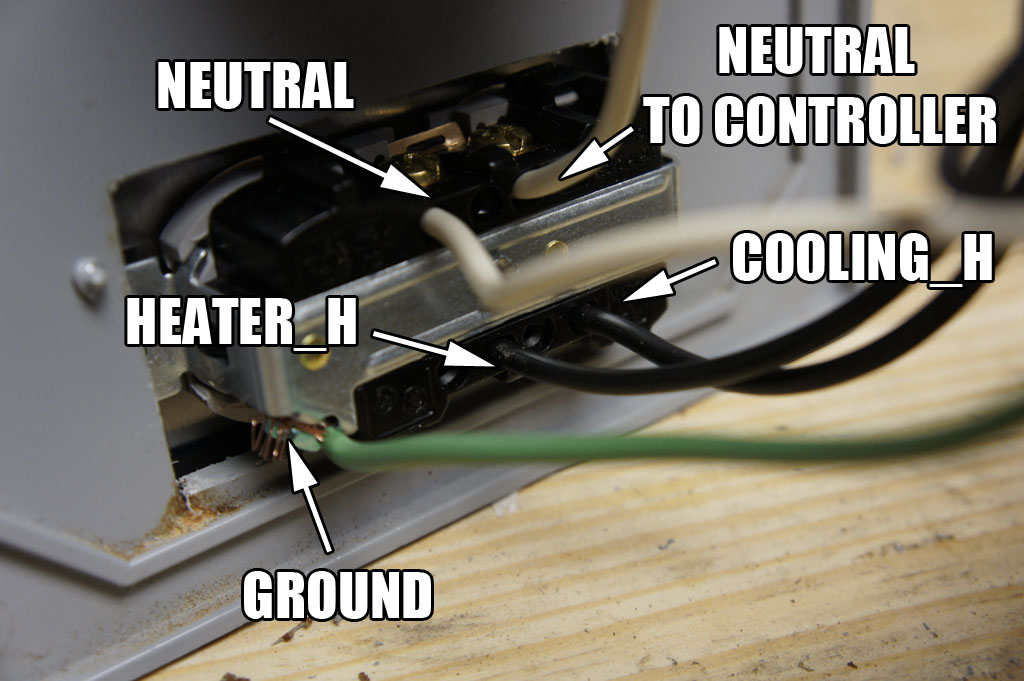
Back view of the socket. The Neutral from the extension cord comes here first then another wire goes up to the controller. The Heater_H and Cooler_H wire into the side that the tab was cut on.
After all that you should be done. Test is to ensure it is working correctly.
Happy Brewing!
Homebrew Fermentation Temperature Control
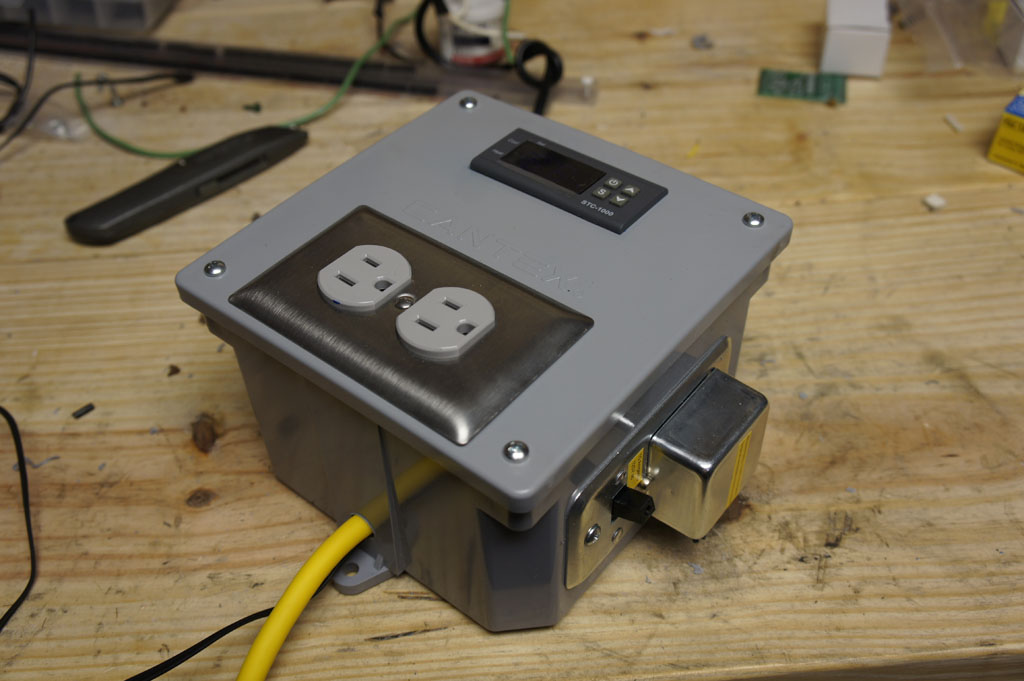
This is my Temperature Controller for my fermentation freezer for homebrew beer. It uses a Digital STC-1000 Temperature Controller which controls two relays. One relay for the cooling and one for heating. The cooling relay is hooked up to the compressor of a chest freezer and the heating relay is hooked to a 60 Watt space heater.
I will be uploading the DIY guide tomorrow.
Dual Motor Driver LaunchPad Booster Pack Built….IT WORKS!
NES2 3D Printed Portable Wrapup!
I finished this project last year for San Mateo Maker Faire but never made a video….TILL NOW!
Been awhile since I last posted but I am pretty much moved into my new place in Houston and getting back to my personal projects.

