Category Archives: PCBA & ENG

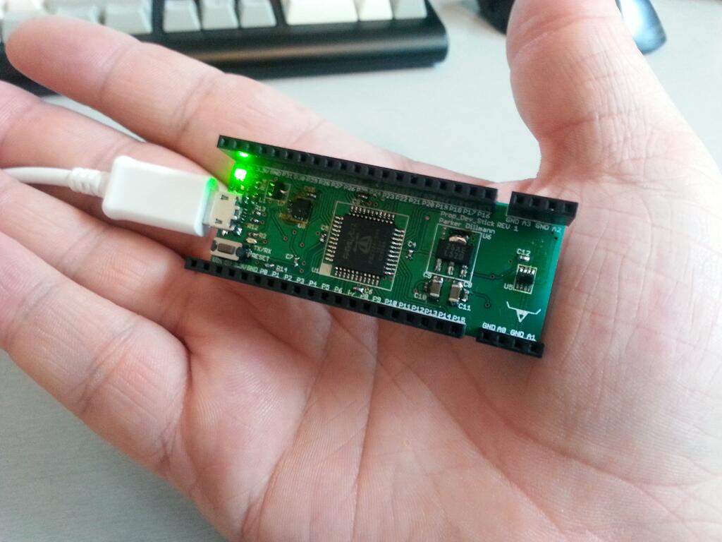
Prop Dev Stick Rev 1 Tested. Fully working.

The Propeller Development Stick (PDS or Prop Dev Stick for short) is a simple development board for the Parallax Propeller Microcontroller. I already had an older design but I wanted to expand the usefulness of the platform. The Redux version throws out the old version completely and starts over from scratch.

The new PDS features a ADC and a micro SD card slot for storage. Also the speed of the Propeller gets a 16MHz speed bump (from 80MHz to 96Mhz) with the addition of a 6Mhz crystal. Form factor is improved by slimming down the design which enables it to fit on a breadboard. The old USB male plug is gone and it now uses a standard micro USB. This way the user can embedded the device and still program or pull data off of it.

It fully complies with the USB standard. The device uses the FT230X USB to Serial chip and waits to turn on the power buss in till the PC gives the device permission to pull power. This is done by a p-channel mosfet. To switch from USB power to external power (like a battery) a power mux is used. The mux has built in current limiting which is set to 500mA.

BPl27j-CEAEXjB0

Last night I soldered the new REV 1 board. Everything is working correctly and the footprints/silkscreen are also correct. Will be working on the page documenting the progress of the PDS. Will also upload the design files.

BPodMdVCIAAVsm4

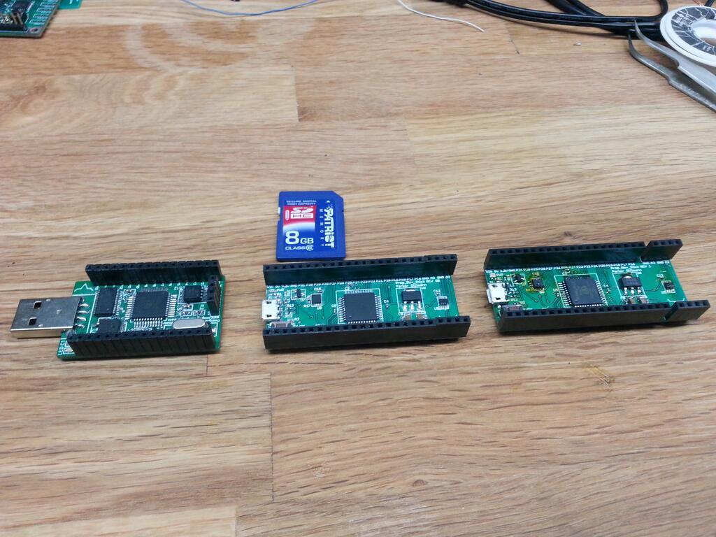
Progression from the first PDS on the left to the newest one on the right. Slightly longer but slightly thinner now. Changed the USB port to a micro usb port. Added an ADC and mirco SD card slot.

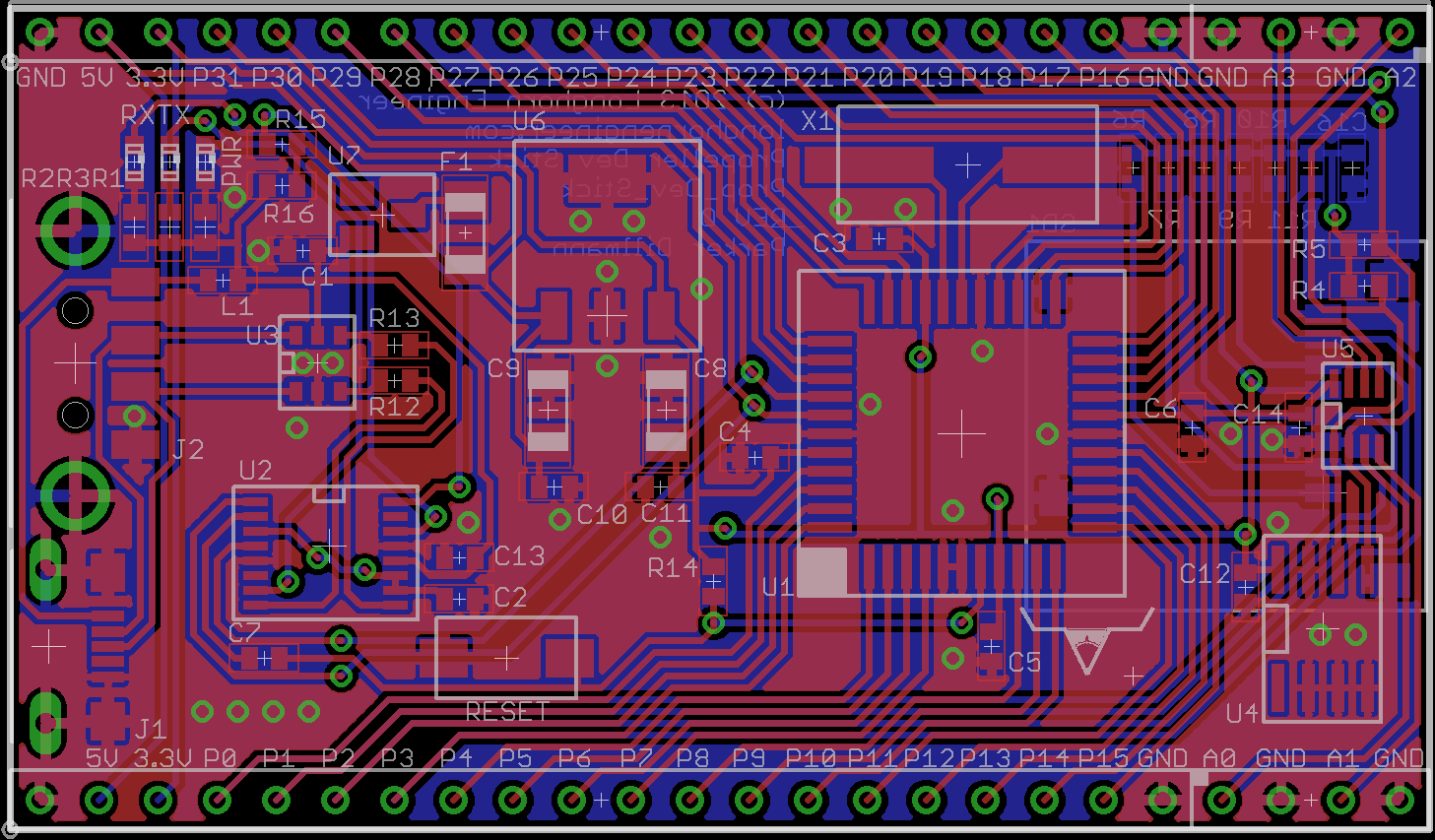
Layout_PDS_REV1

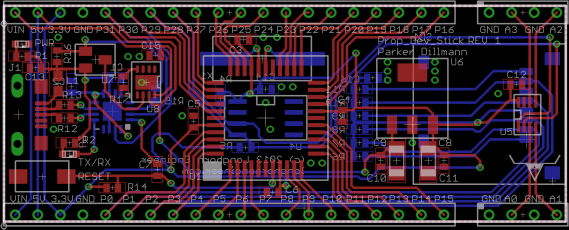
Layout of the PCB.

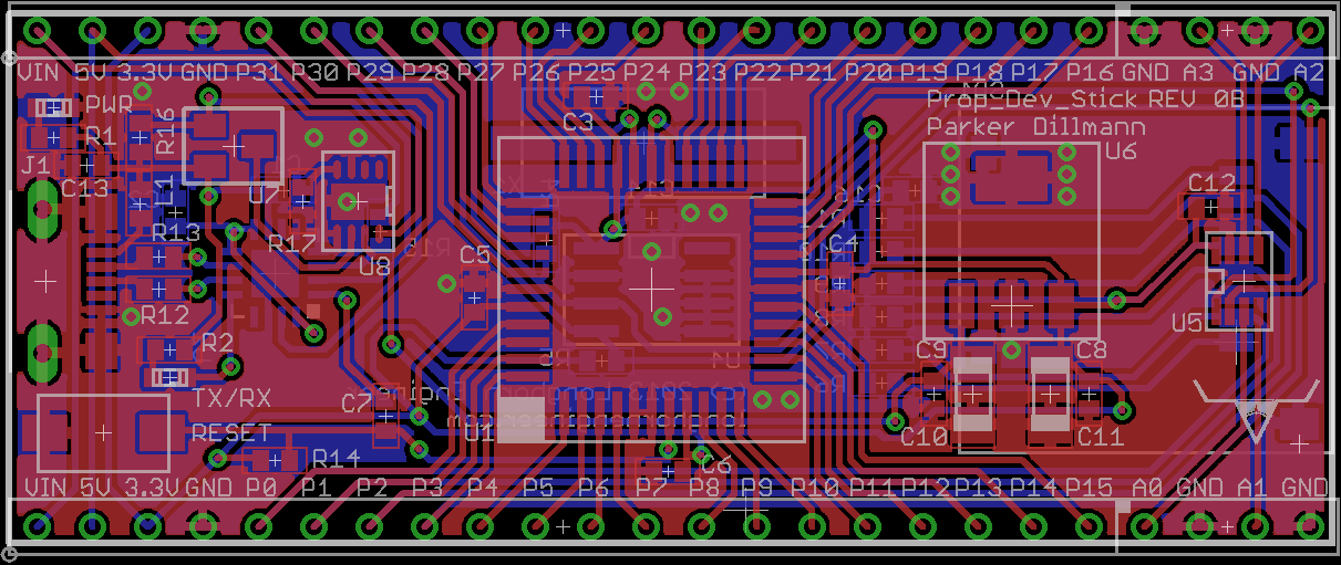
Prop Dev Stick REV 0B

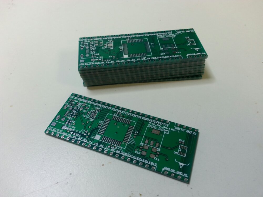
Finished REV 0B for the Prop Dev Stick. I minimized the size of the board from 1.5″ to 1″ wide. It is now thin enough to plug into a bread board. Width between the two rows of headers is 0.9″.

Some quick specs. Running the propeller at 96MHz, Micro SD card slot, 4 channel 8-bit ADC, built in USB, and all I/O brought out to the edge. A power MUX controls whether or not the Prop Dev Stick uses USB power or power from an external source like a battery. This way you can have the unit running off battery or solar and still use the USB connection for serial data. When an external power source is absent the mux switches over to USB power.

Prop Dev stick…a PCB?

In this case PCB stands for Phoenix Circuit Board. I have not worked on this project since September 2011.

The Prop Dev Stick is a Parallax Propeller development platform that is designed to just plug into a computer like a USB thumb drive. The old design was just the Propeller MCU with no frills. This time around I added a micro SD card slot and a ADC for reading sensors.

ISR PWM Motor Control

This code runs the Low Voltage Motor Booster Pack for the MSP-430 with the MSP430G2553 chip but could easily be adapted to any microcontroller. This uses Timer1_A0 to make a timing interrupt. Using the timing interrupt it changes the duty cycle of the PWM. Supports reverse by sending the “move_motors” command negative values.

Default is P2.0, P2.1, P2.2, and P2.3 for controlling the motor driver. P1.0 is toggled (on board LED) in the ISR.

Code: CCS V5


isr_motor_pwm.c
isr_motor_pwm.h
Project File Ver1.0


/*
*isr_motor_pwm.c
*Version: 1.0
*Parker Dillmann
*The Longhorn Engineer (c) 2013
*www.longhornengineer.com
*
*Check bottom of file for License.
*
*/

#include "msp430g2553.h"
#include "isr_motor_pwm.h"

#define Motor_DIR P2DIR
#define Motor_OUT P2OUT

#define Motor_A1 BIT0
#define Motor_A2 BIT1
#define Motor_B1 BIT2
#define Motor_B2 BIT3

volatile int Motor_Speed_A;
volatile int Motor_Speed_B;

volatile int Motor_isr_cnt;

void init_motors(void)
{
TA1CCTL0 = CCIE;             //Enable the CCR0 interrupt
TA1CCR0 = 50000;             // Set the interrupt register to "trip" each 50000 cycles"

TA1CTL = TASSEL_2 + MC_2 + TACLR;     //Timer_A Source Select; Set source to SMCLK, continuous mode, clear TAR

P1DIR |= 0x41;                            // P1.0 output

Motor_DIR |= (Motor_A1 | Motor_A2 | Motor_B1 | Motor_B2);    //Set Motors to output
Motor_OUT &= ~(Motor_A1 | Motor_A2 | Motor_B1 | Motor_B2);    //Set Motor outputs to 0

Motor_isr_cnt = 1;

return;
}

void move_motors(int Speed_A, int Speed_B)
{
Motor_Speed_A = Speed_A;
Motor_Speed_B = Speed_B;
return;
}

void stop_motors(void)
{
Motor_Speed_A = 0;
Motor_Speed_B = 0;
return;
}

#pragma vector = TIMER1_A0_VECTOR
__interrupt void Timer1_A0_ISR(void)
{
//Upkeep Time
Motor_isr_cnt++;
if (Motor_isr_cnt == 512)
{
Motor_isr_cnt = 1;
}

//Motor_A PWM
if (abs(Motor_Speed_A) >= Motor_isr_cnt)
{
if (Motor_Speed_A > 0)
{
Motor_OUT |= Motor_A1;
Motor_OUT &= ~(Motor_A2);
}
else
{
Motor_OUT |= Motor_A2;
Motor_OUT &= ~(Motor_A1);
}
}
else
{
Motor_OUT &= ~(Motor_A1 + Motor_A2);
}

//Motor_B PWM
if (abs(Motor_Speed_B) >= Motor_isr_cnt)
{
if (Motor_Speed_B > 0)
{
Motor_OUT |= Motor_B1;
Motor_OUT &= ~(Motor_B2);
}
else
{
Motor_OUT |= Motor_B2;
Motor_OUT &= ~(Motor_B1);
}
}
else
{
Motor_OUT &= ~(Motor_B1 + Motor_B2);
}

  P1OUT ^= 0x40;    // Toggle P1.0
TA1CCR0 += 500;  //Add offset to CCR0
}

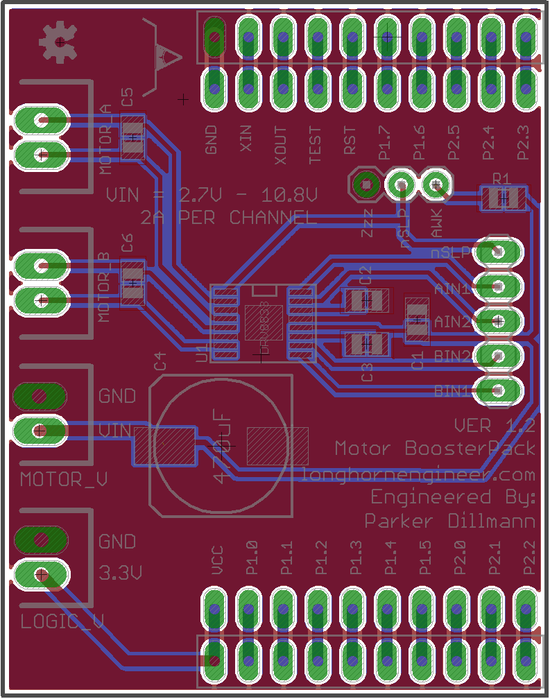
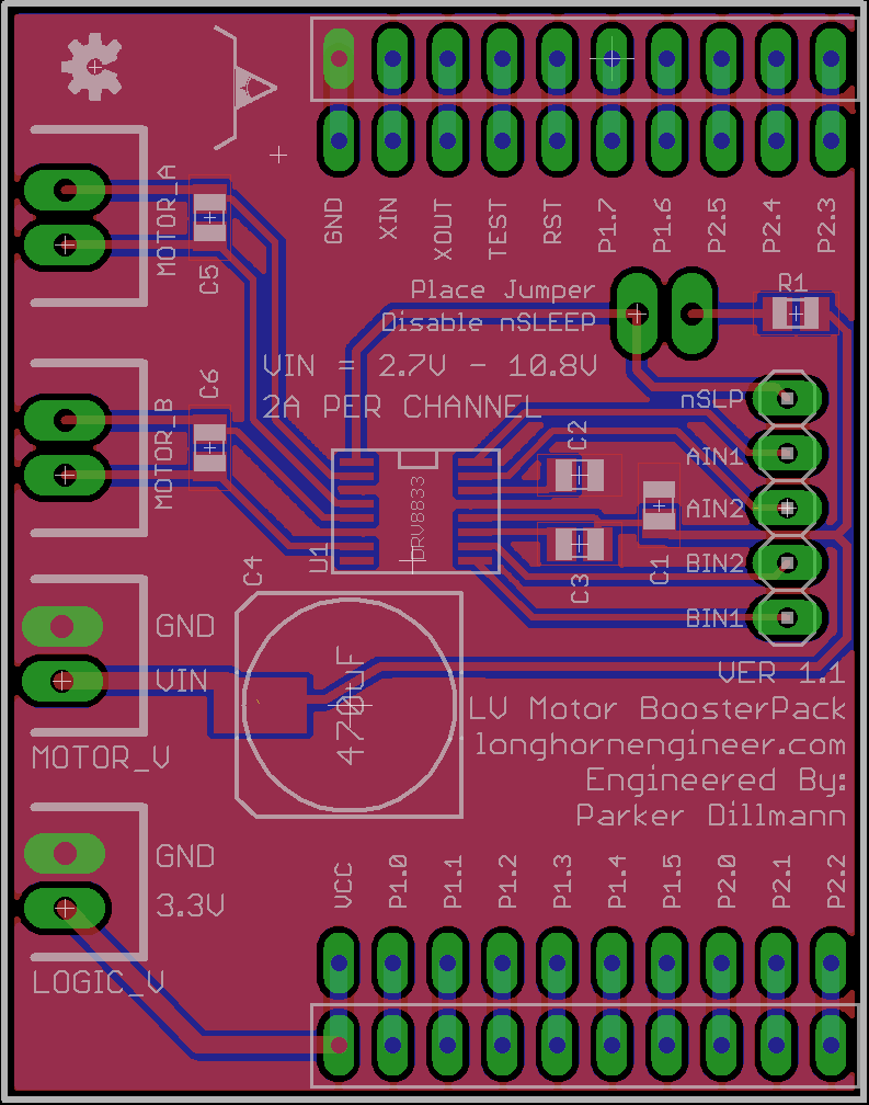
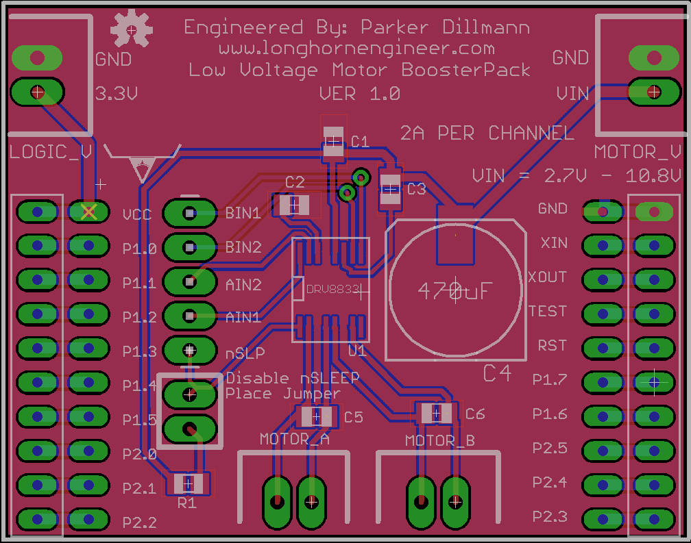
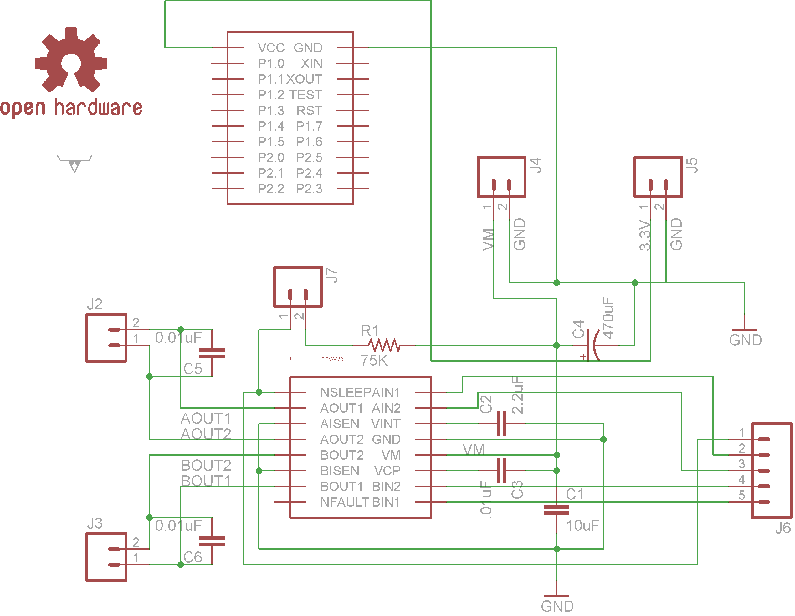
2A Low Voltage Motor Driver BoosterPack Ver1.0

This is a Low Voltage, 2A motor controller BoosterPack for the Ti LaunchPad. So far I have not found a motor controller yet so I decided to make one. This is the first in many BoosterPacks I will be designing and selling. It uses the Ti DRV8833PWPR Dual H-bridge Motor Driver chip. The chip is capable of 2Amps per motor channel and a motor voltage from 2.7V to 10.8V. Logic voltage for the DRV8833 is 3.3V which makes it a perfect match for the MSP-430 LaunchPad.

The BoosterPack has the nSleep pin broken out from the DRV8833. Using this pin will put the DRV8833 to sleep to minimize current draw. If this pin is not needed or the LaunchPad is lacking I/O there is a jumper to pull the nSleep pin high.