To read oil and coolant temperature on the Jeep I wanted to use automotive parts for the sensors. Most temperature sensors in the automotive world are thermistors. I searched around for some in 1/8″ NPT and found some designed for aftermarket gauges. Only problem was there was no datasheet for them…which is necessary to accurately read the thermistors since they are non linear devices. At under $4 a piece I ordered them anyways.
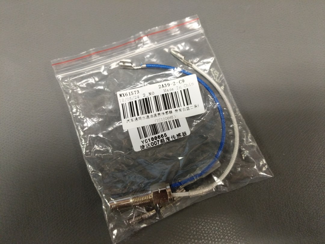
Fortunately when they arrived they had a part number on them and after some googling I managed to find a temperature chart.
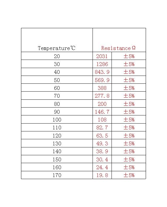
I double checked the values with a multimeter and setting the hot air gun to the temperatures in the chart above and seeing what the resistance was. Everything matched.
To read the thermistors I decided to use the MAX6682 IC. This IC gets rid of power supply noise and thermal self heating of the thermistor.
The only thing I had to calculate was the REXT value. I used the 2031 ohm (20C) for RMAX, 108 ohm (100C) for RMIN, and 388 ohm (60C) for RMID. This came out to a value of 287 ohms. Which the resistor ERA-3AEB2870V by Panasonic works. See page 6 of the datesheet for the formula to calculate REXT.
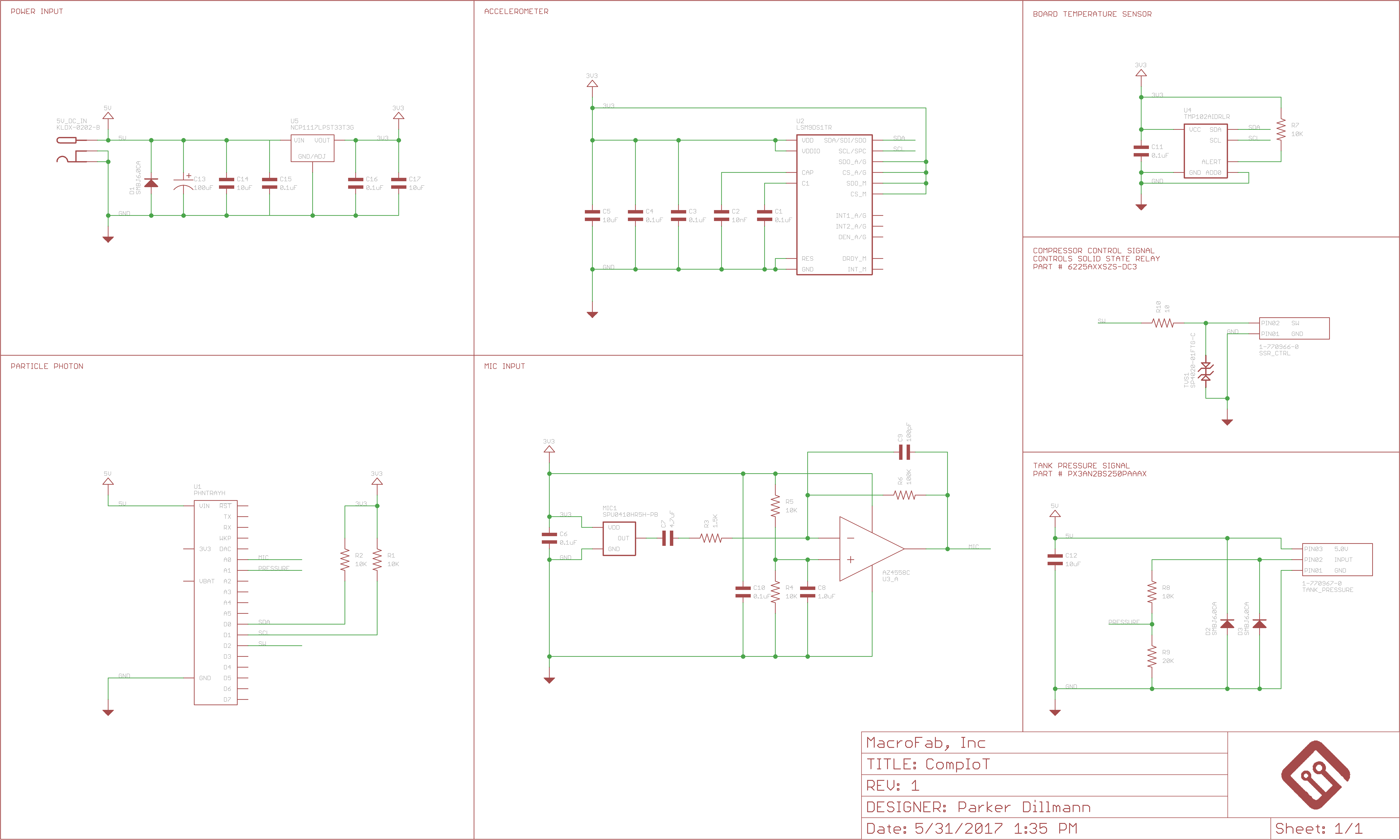
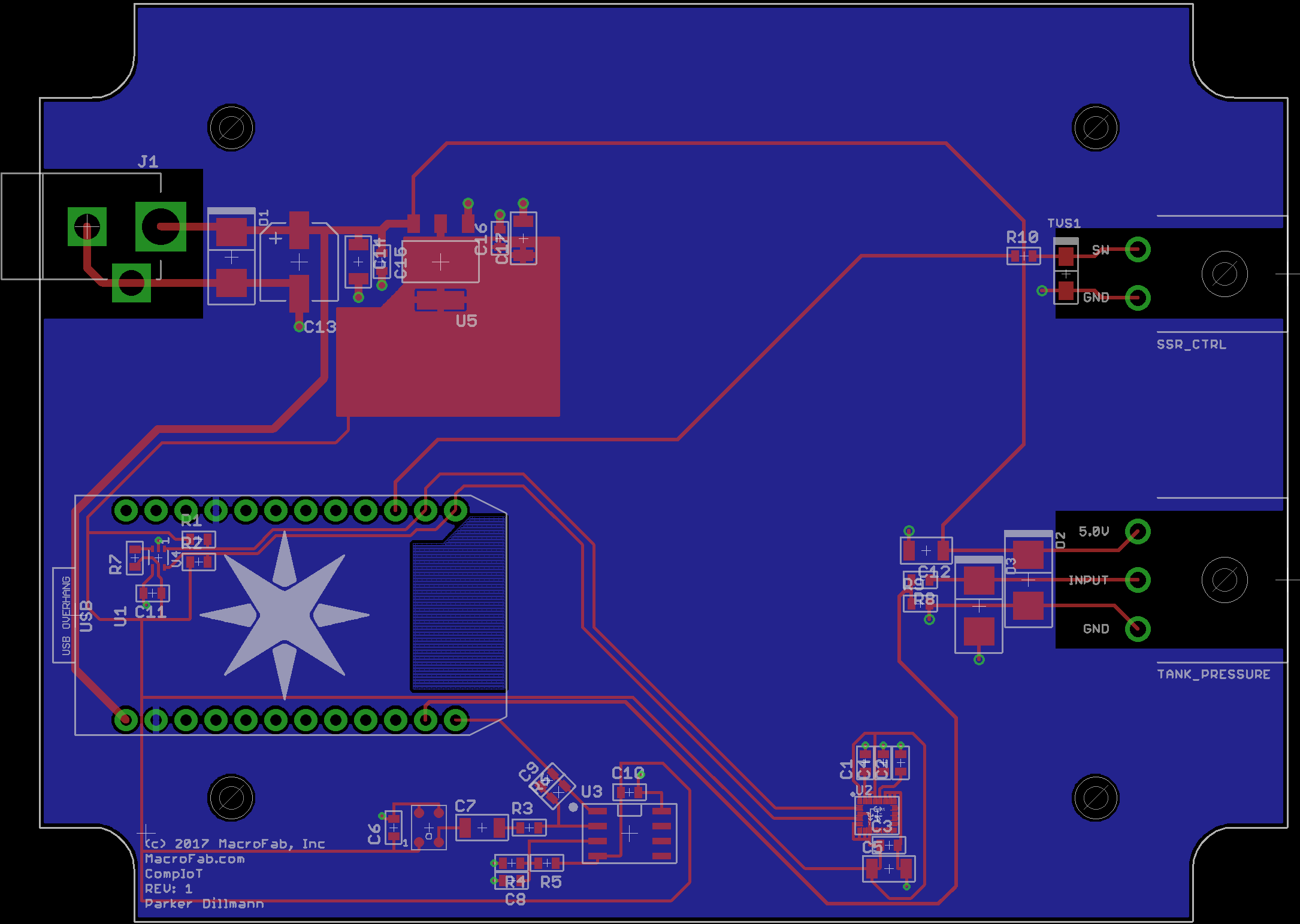
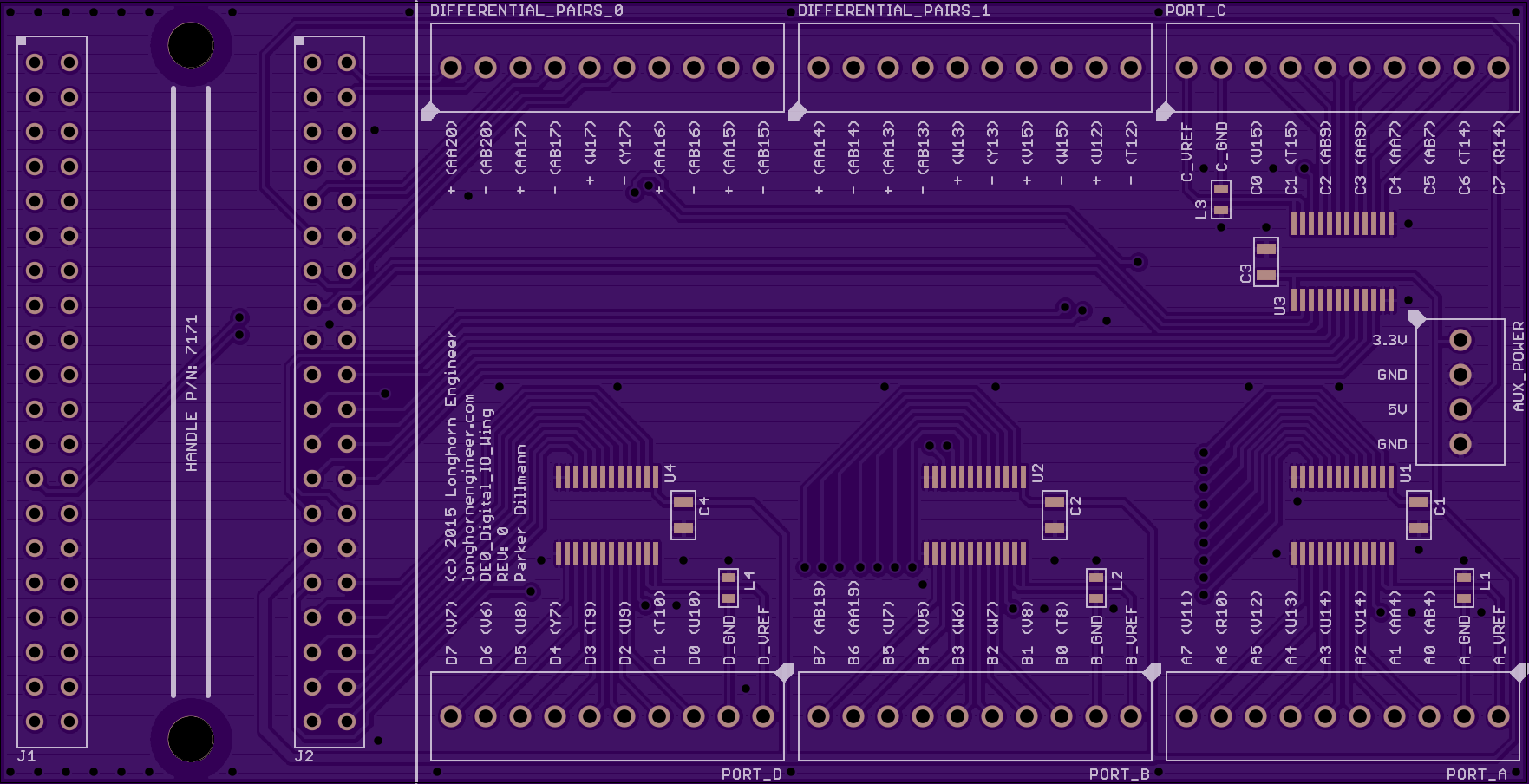
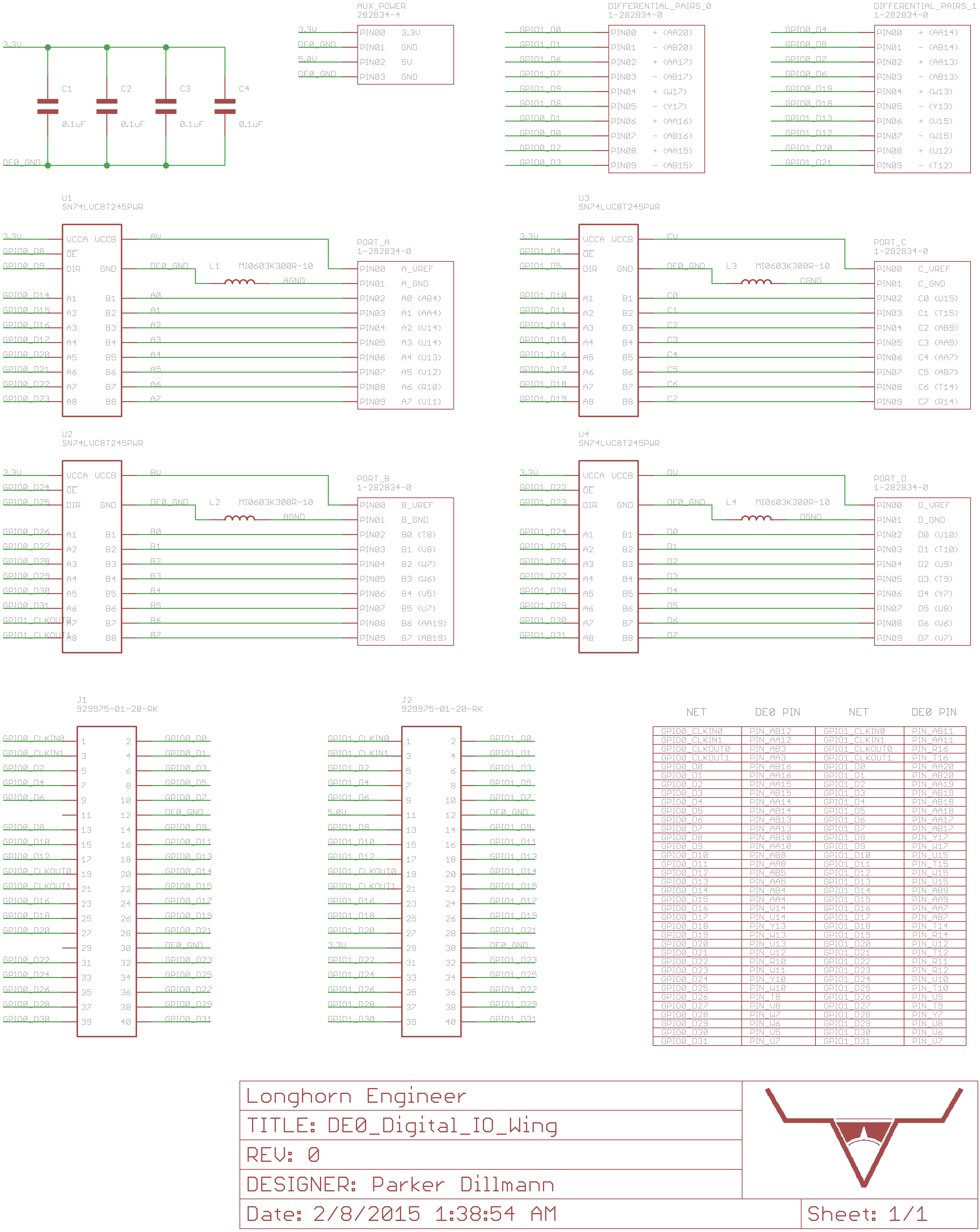
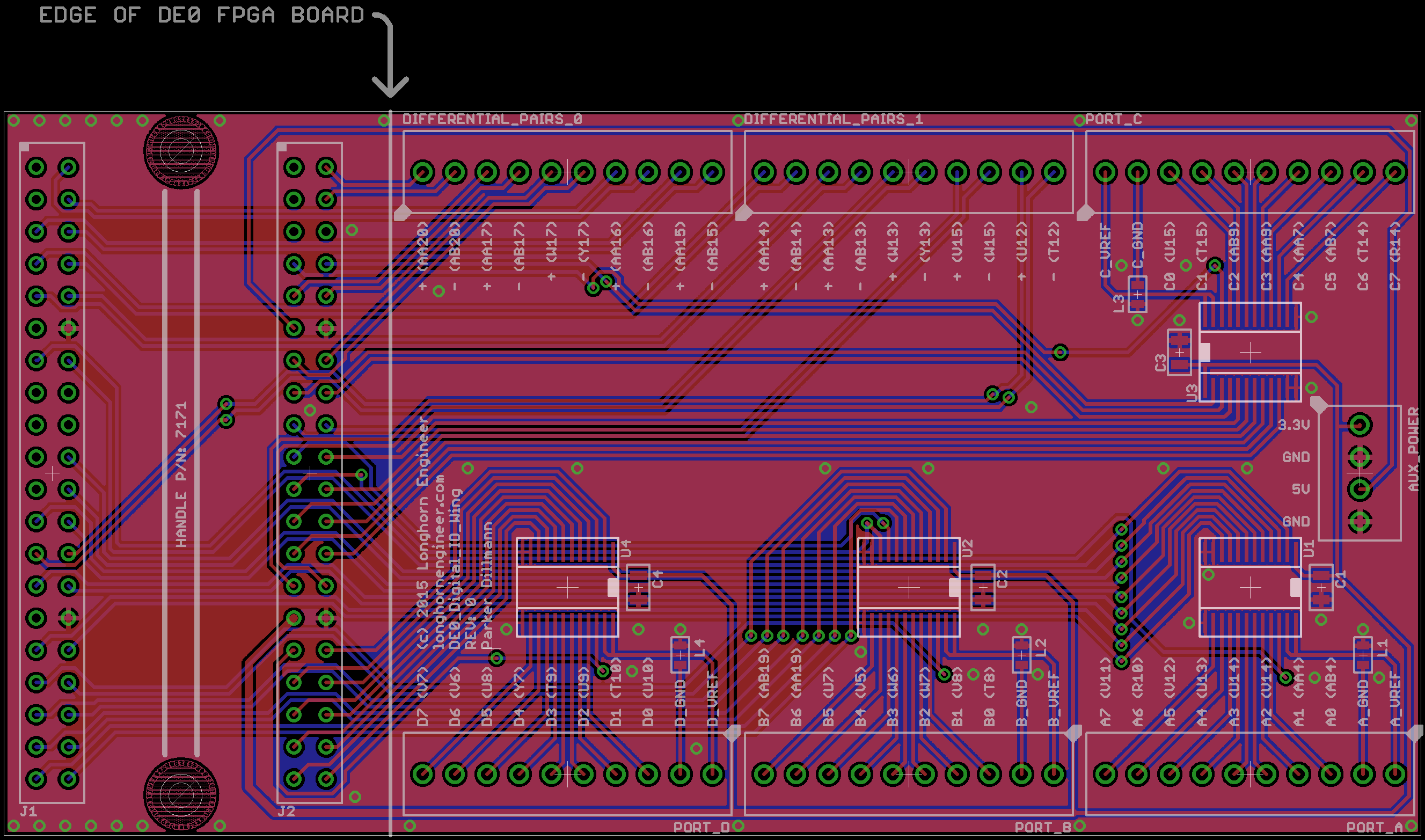
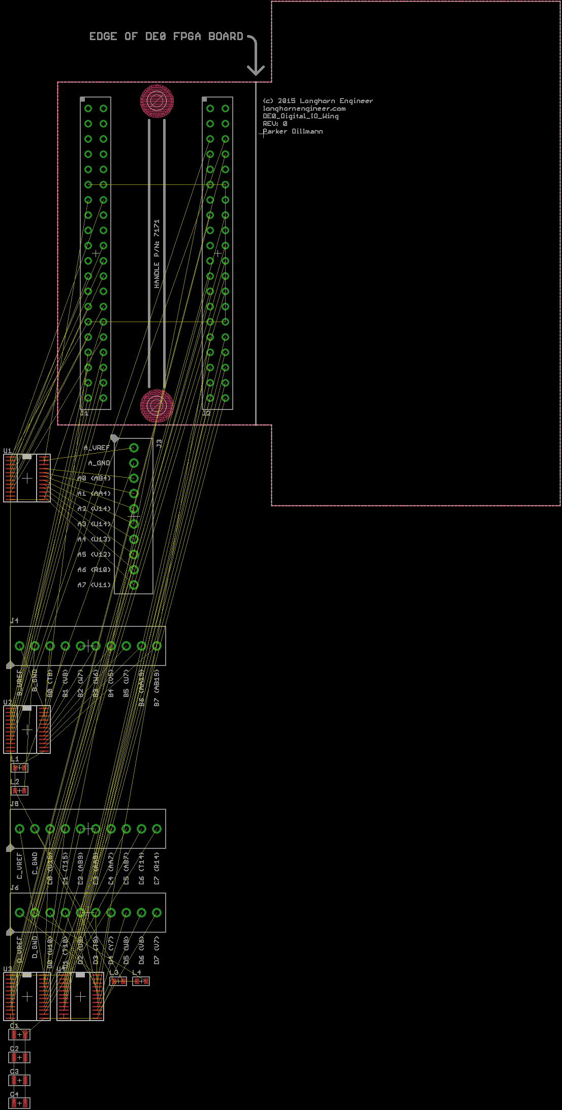
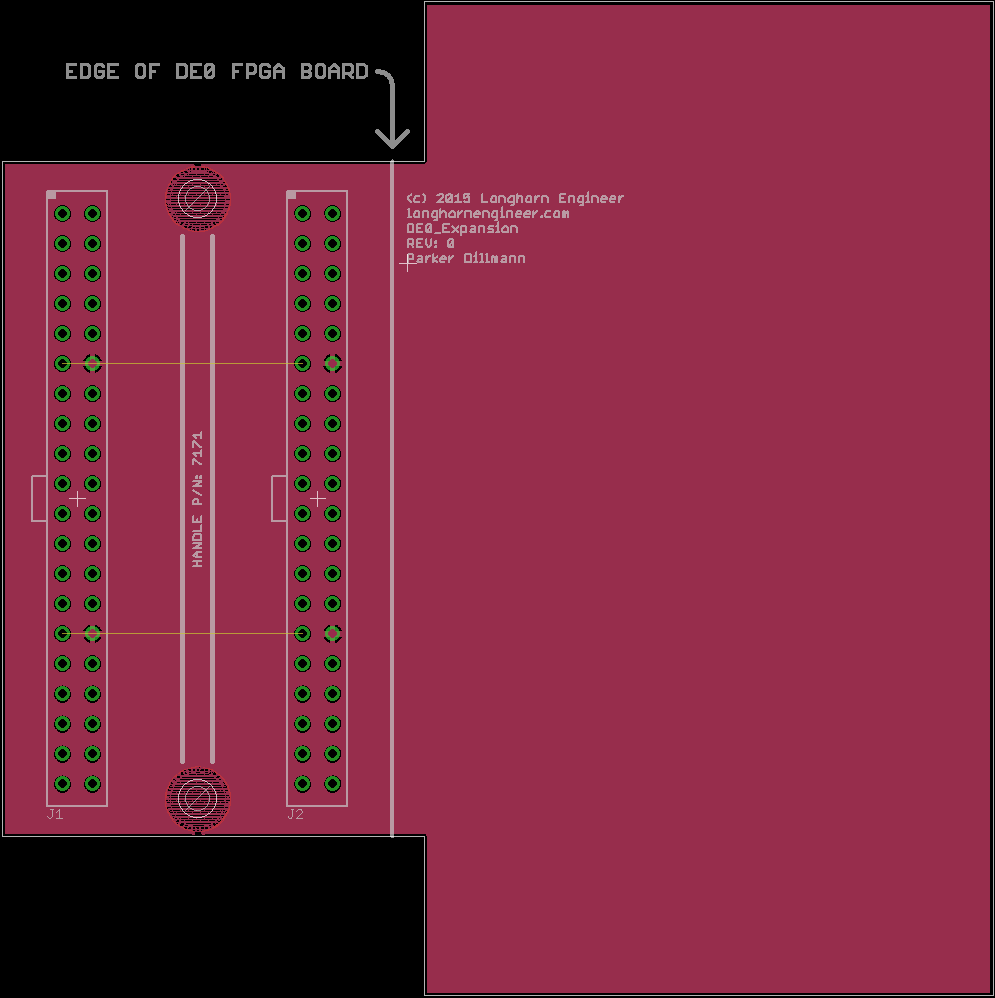
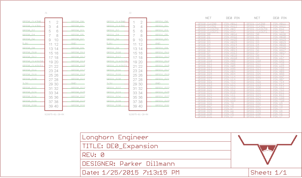
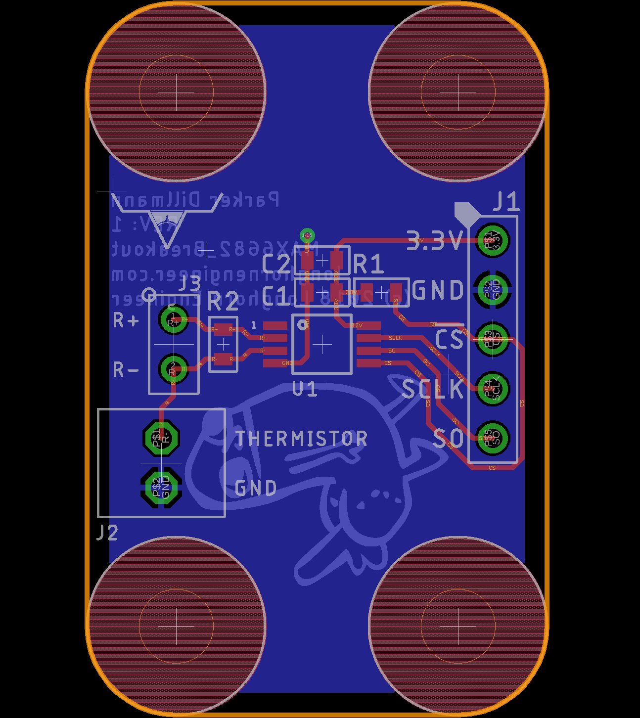
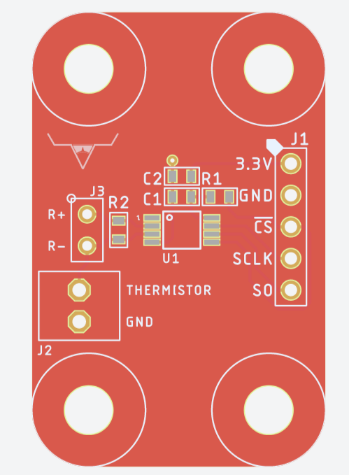
Then I drew up the schematic and layout for the breakout board.
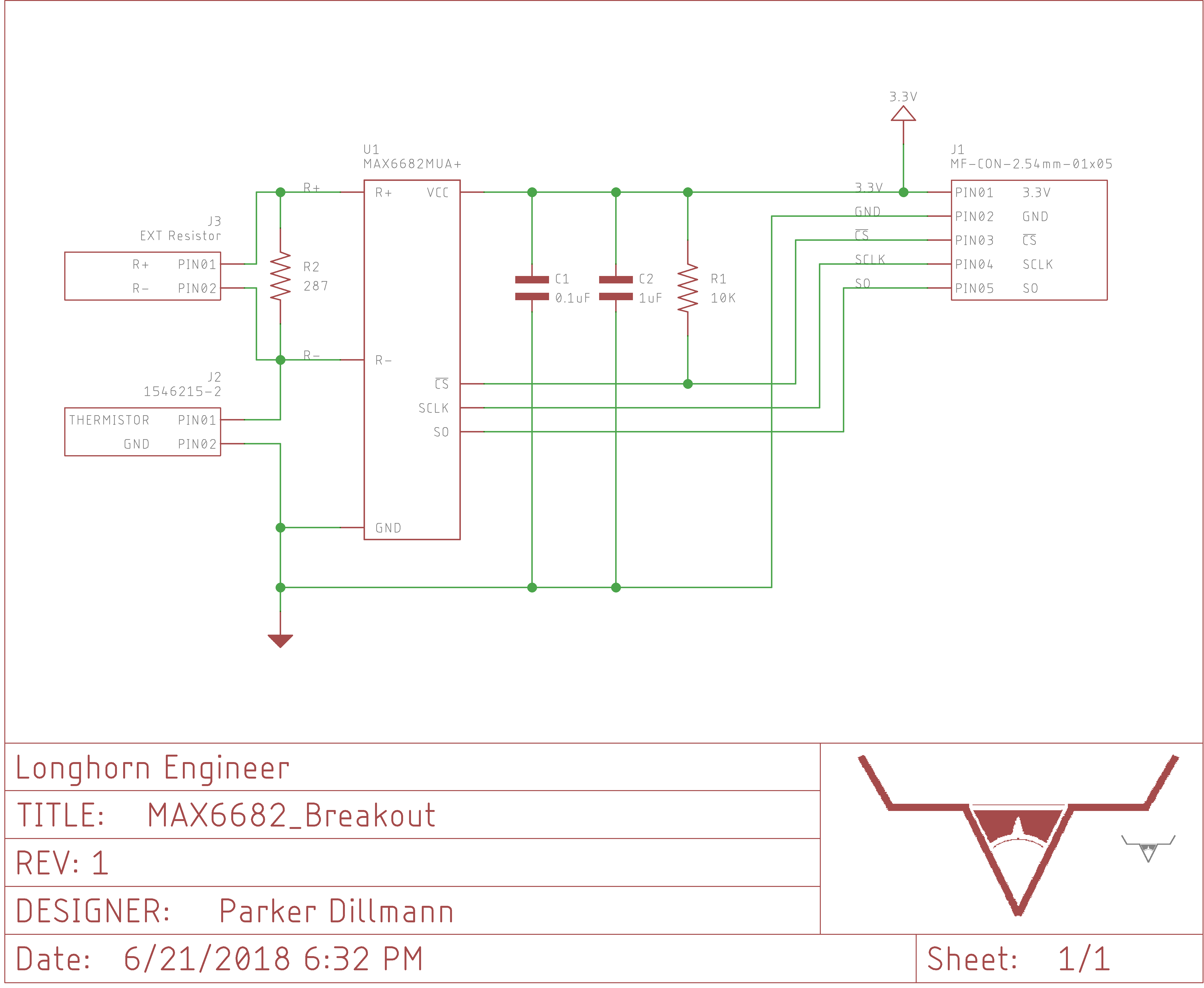
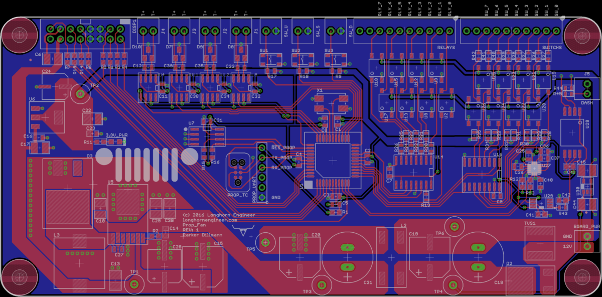
I added a little header (J3) that will allow me to easily change the REXT value for other thermistors.
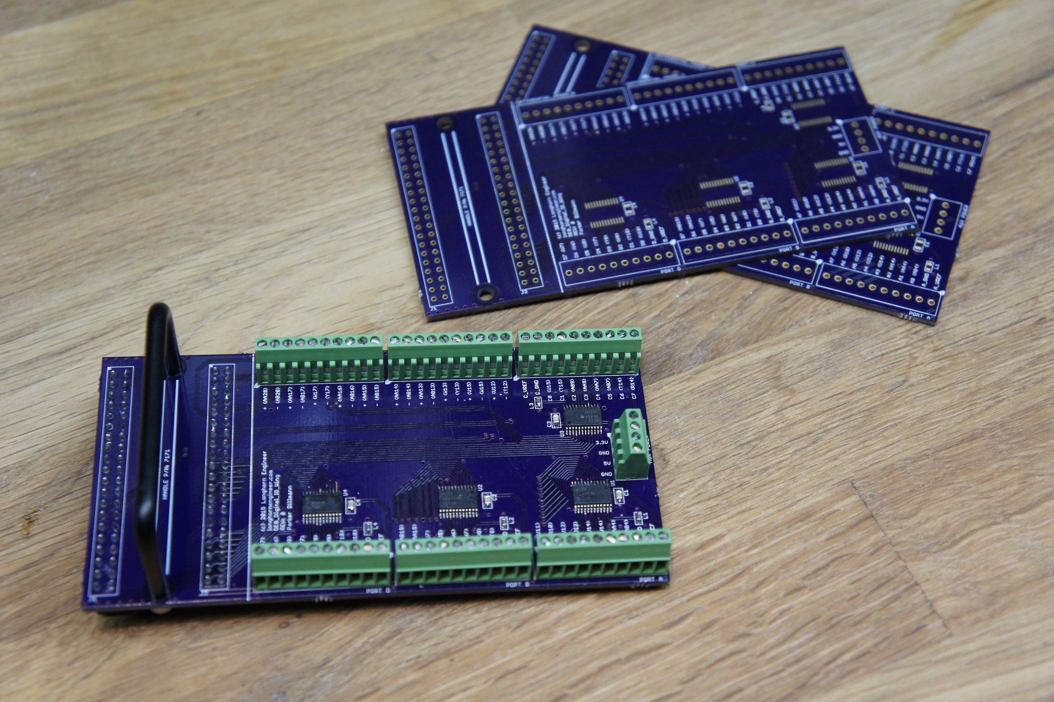
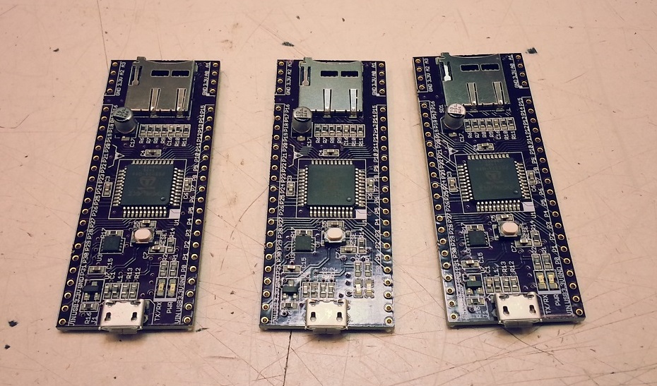
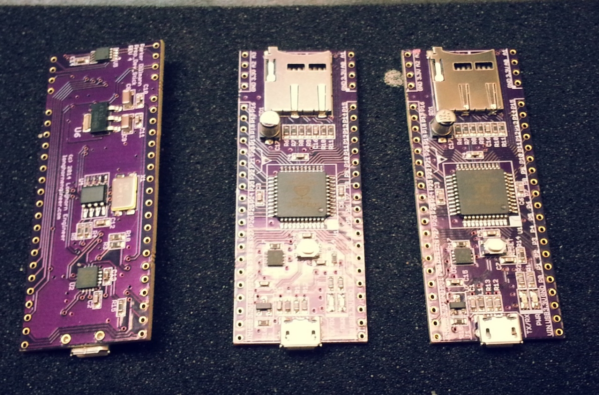
Boards ordered!