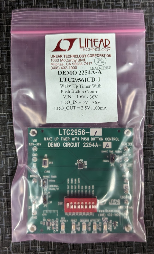
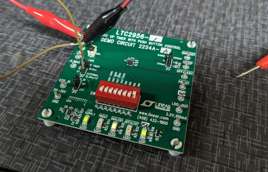
For keeping the time for the Cat Feeder Unreminder I am planning on using the LTC2956-1 which is a super low power timer that has push button reset control. It can accurately handle very long timers that a traditional RC style timers (think 555 timer) wouldn’t be able to do.
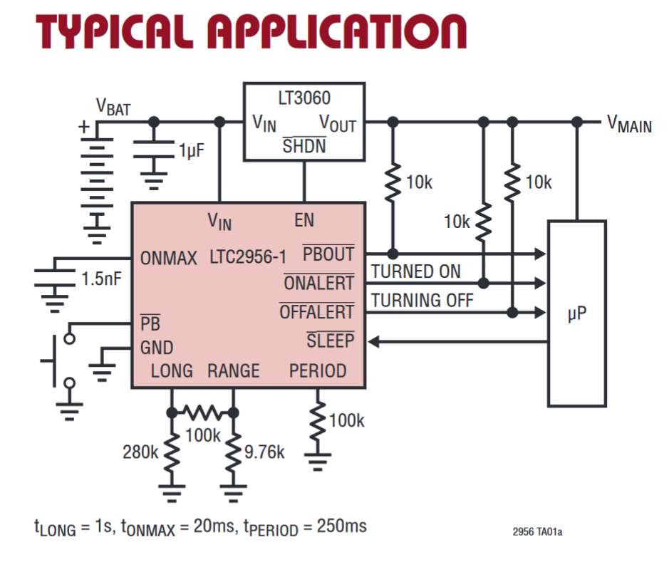
For my use case, I am going to pull ONMAX to GND which will disable the timer that turns off the AWAKE timer. I will toggle the Sleep pin from low to high to low to reset the timer.
To handle the timing aspect of the Cat Feeder Unreminder I am going to use the Analog (It is actually a Linear Technology part!) LTC2956 timer component.
This is a wake up timer IC that has built in push button support for reset. Perfect for this project.
The timer itself is configured with just a few resistors and can range from 250ms to 39 days. Setting it to the required 22 hours is a piece of cake for this timer.
In shutdown, it only pulls 800nA while active and 300nA in shutdown mode which is one of the lowest current use for a timer that I can find.
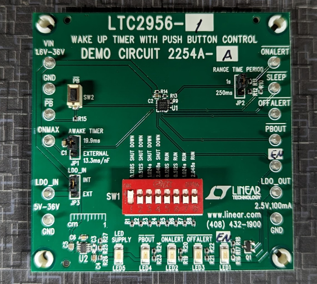
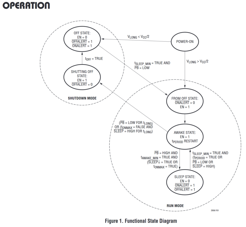
To set this up for the Cat Feeder Unreminder we need to stay in RUN MODE. The device can’t leave SHUTDOWN MODE without interacting with the PB switch and that would make for a hungry cat. The AWAKE STATE with EN=1 is when the device will tell us to feed the cat. SLEEP STATE with EN=0 is in standby counting till next feeding
ONMAX to GND
This sets the T ONMAX time to the max
T ONMAX will stay FALSE
We don’t want the device to auto fall into the SLEEP STATE
SLEEP to a switch
We will use this to send the device to the Sleep State
Active Lowq
Set LONG to max time
Tie PB HIGH
Makes sure we don’t fall into SHUTDOWN MODE
Set Period/Range for timer to activate in 22hrs
This should allow the EN pin to go high every 22 hours and will reset low when the push button on PB is pressed.
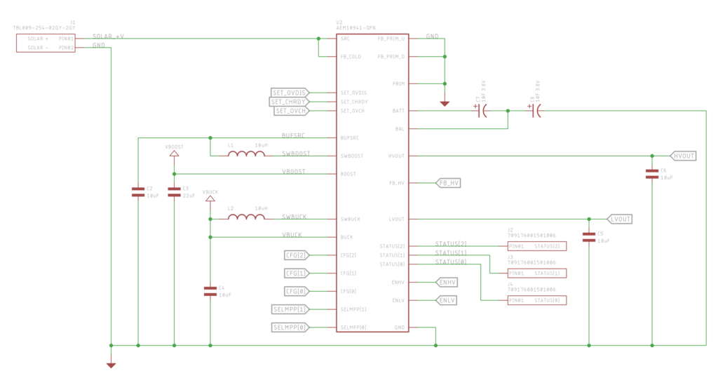
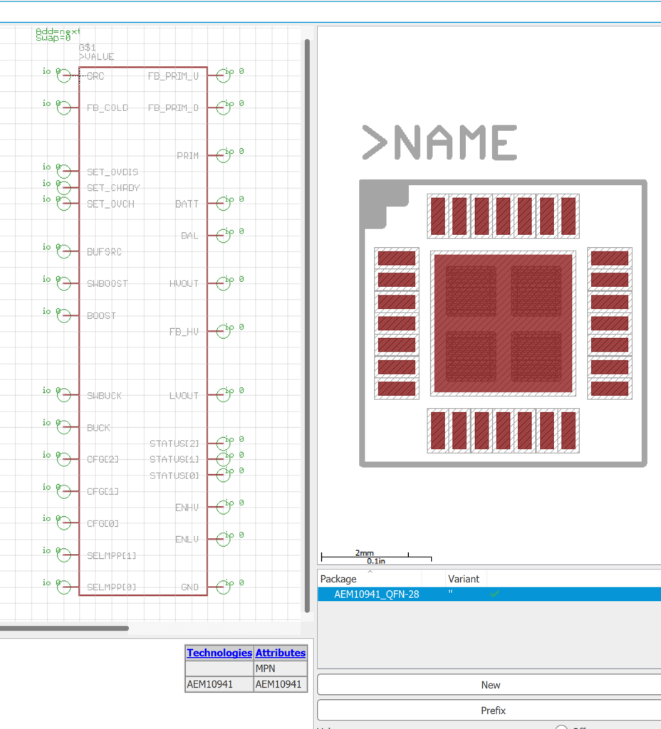
Just wrapped up the schematic side for the AEM10941 portion of the Cat Feeder Unreminder.
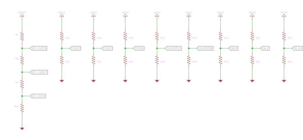
I broke out all the configuration pins to their own pullup / pulldown combos so I can experiment with voltage cutoffs for the super capacitors. Most likely leave most of configuration resistors unpopulated!
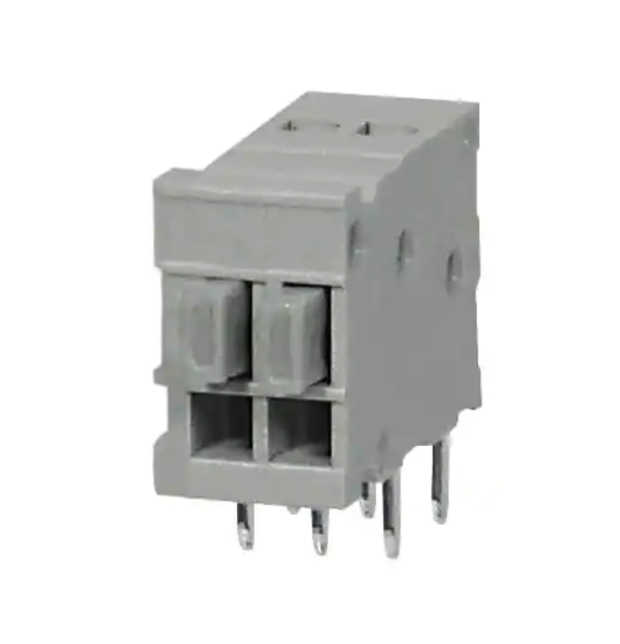
I found these really neat push button terminals that I am going to try to use for attaching the solar panel to the PCB. Part Number: TBL009-254-02GY-2GY
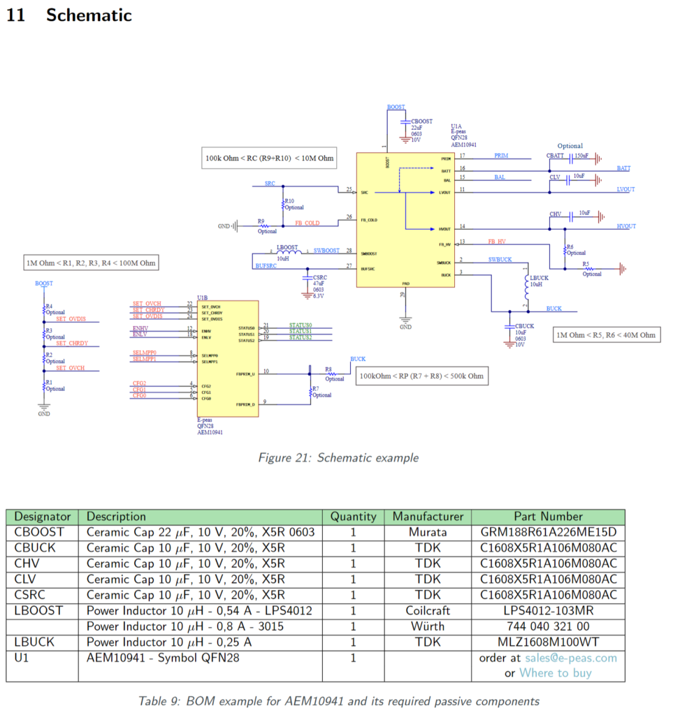
For the Cat Feeder Unreminder, the AEM10941 “ambient energy manager” has built in boost and buck regulators. These need external components like capacitors and inductors to function.
The example schematic in the datasheet for the AEM10941 looks like this and has these recommended components.
Schematic from the Datasheet for the AEM10941
The capacitors are just your standard 0603, which are kinda small for the values. My project can handle larger sizes which will net better performance and lower leakage current.
For example GRM32ER61A106KA01L (10uF 10V X5R 1210) vs GRM155R61A106ME11 (10uF 10V X5R 0402). While its hard to specify leakage current as it varies with voltage, temperature, and frequency you can look at the insulation resistance and the larger the package the larger the insulation resistance.
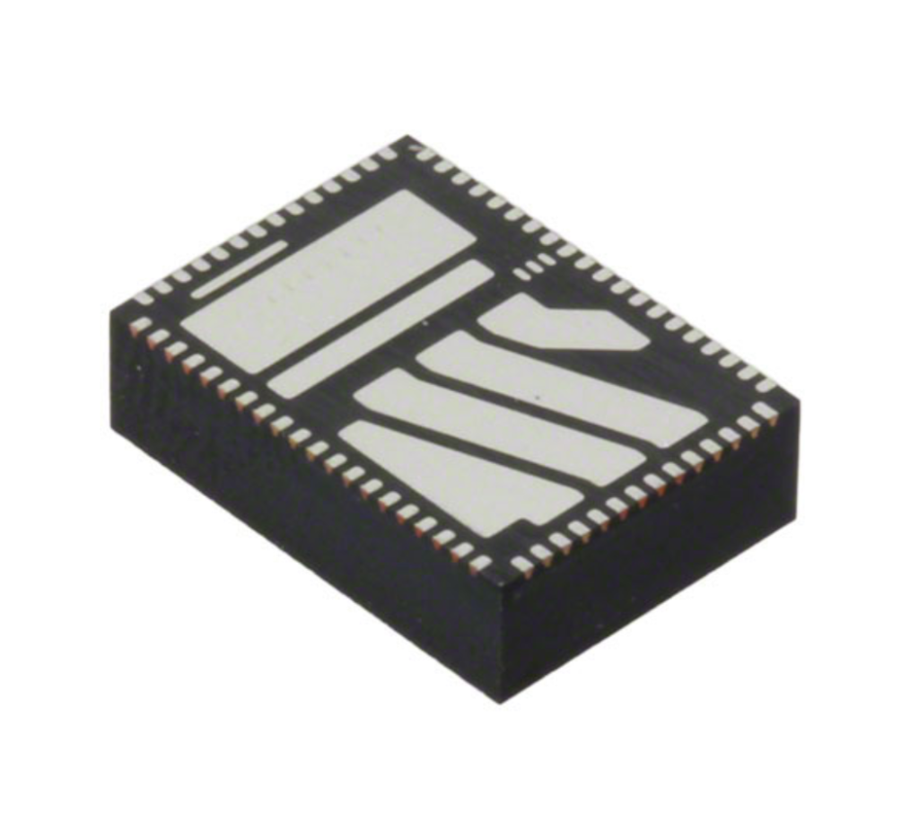
Anyways, enough about capacitors. The Coilcraft inductor the schematic specs is from the LPS4012 series. I didn’t have this family in my EDA tool already designed so I opened up the datasheet to this horror.
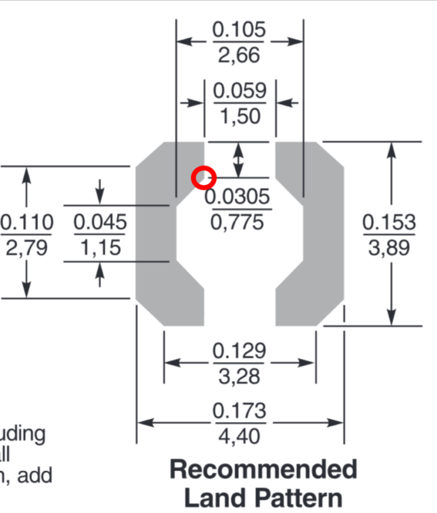
Land pad for the LPS4012 series inductor
This doesn’t look too bad but this showcases one of my pet peeves about how part manufactures dimension parts. Its pretty clear that mechanical engineers dimension parts. PCB Design tools don’t dimension like Mechanical Design Tools. In PCB tools, you typically specify the absolute location of the point/vertex of the line. This is different then Mechanical Design tools where you specify lengths and relationships between points.
For example look at this point right here that I circled in red.
For the EDA tool I use (Eagle) the only way to do this is to tell that point of that polygon is at point (-0.75mm, 1.17mm) assuming the center of the part is (0, 0). X is easy, 1.5mm / 2. Y on the other hand is (3.89mm/2) – 0.775mm. Again just some arithmetic, but this is where the problems occur on validating new footprints and having to spin a prototype again just due to a slip of math.
Part manufacturers either need to give the data in a way that makes it easy to translate into the tools the electrical engineer uses or EDA tools need to become more like Mechanical tools in how you parametrically associate line edges and dimension footprints.
The component EN2342QI, found on the CursedFootprint twitter account.
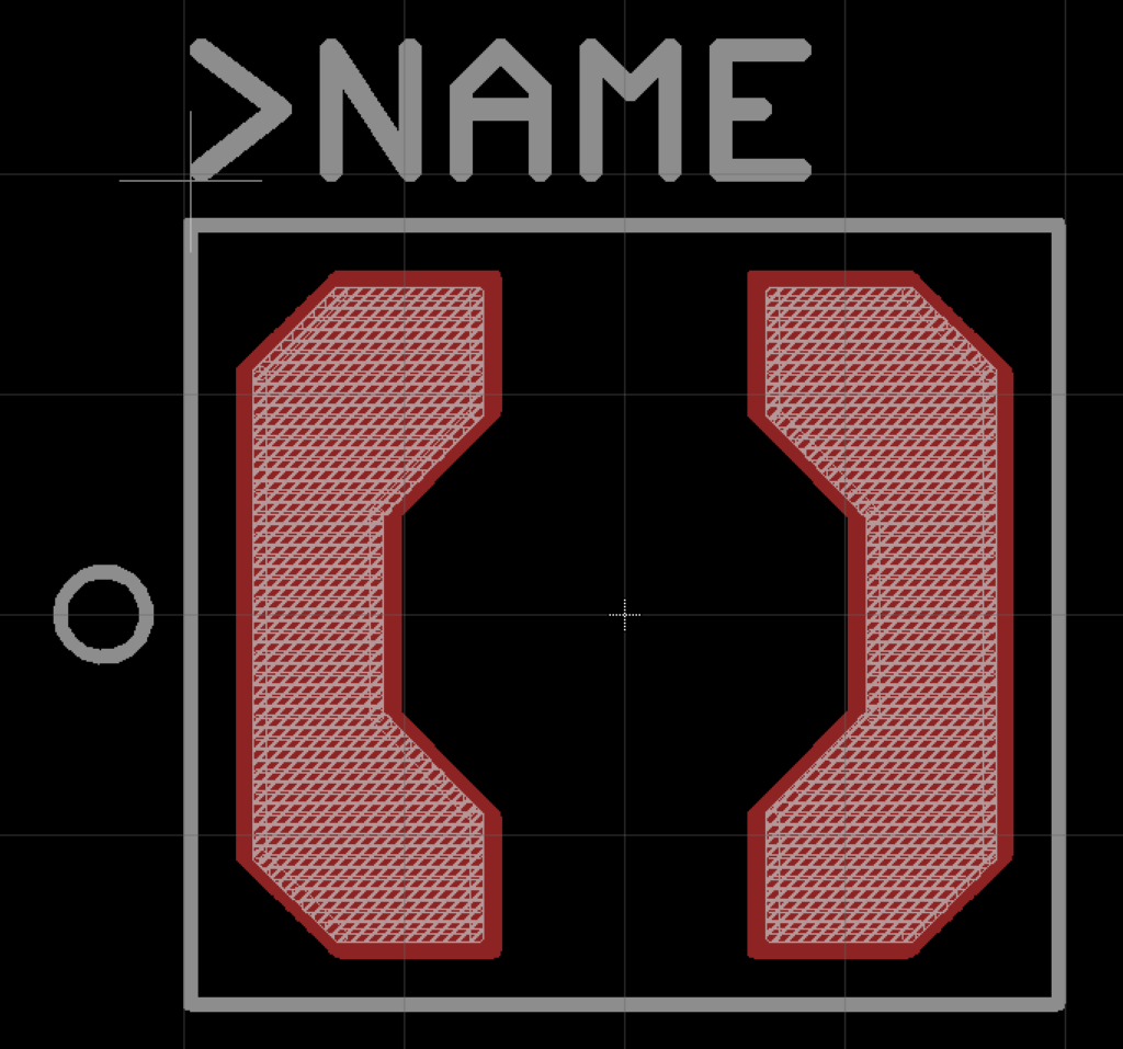
Now, I know that Autodesk has been working on bringing PCB layout design (and maybe schematic?) to the Fusion 360 ecosystem which would solve this problem. I don’t know how far along that product is but I should look into it for the next board I design. If Eagle libraries can be ported over then that would be rad.
Anyways there is the part designed in Eagle. You can get it in my part library which is on github.
In trying to reduce the power consumption of the Cat Feeder Unreminder, I am going to explore using some really low power comparators to build the AC drive voltage I need to run the TN LCD segments.
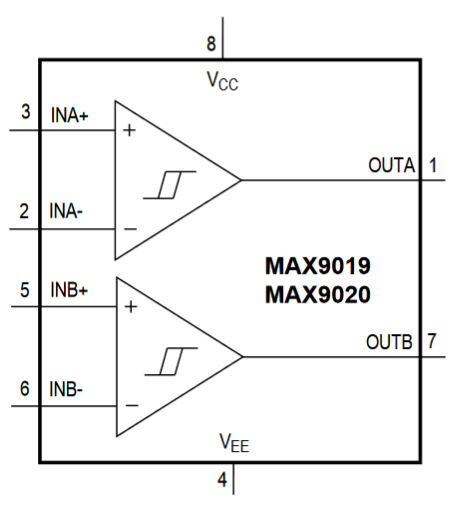
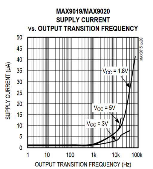
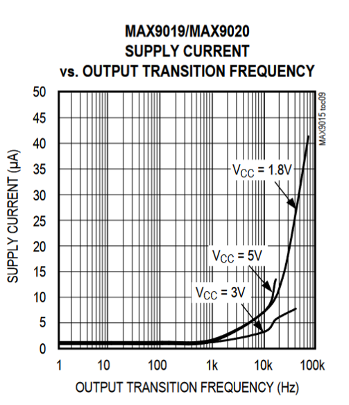
The MAX9019 is a dual package comparator fits the bill in the power requirements.
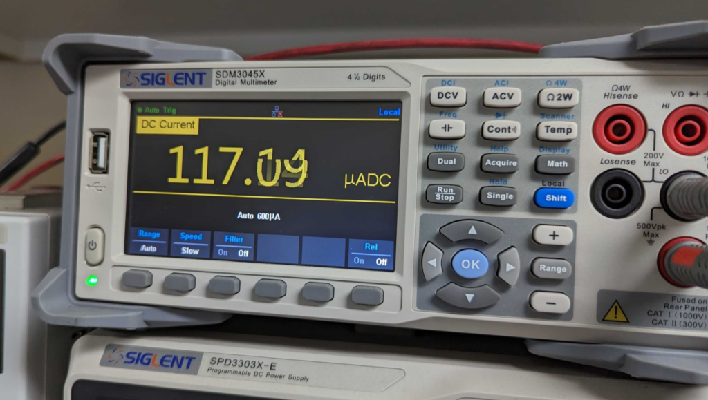
In the switching frequencies I am using (50-100Hz) it should only need a supply current of ~1uA.
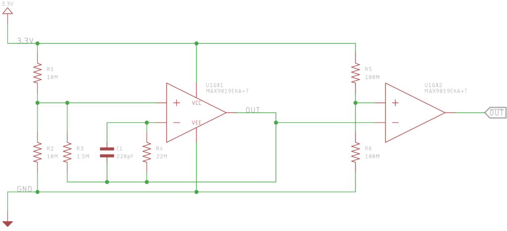
We setup the first comparator to generate a square wave and then the second comparator in the package as an inverter.
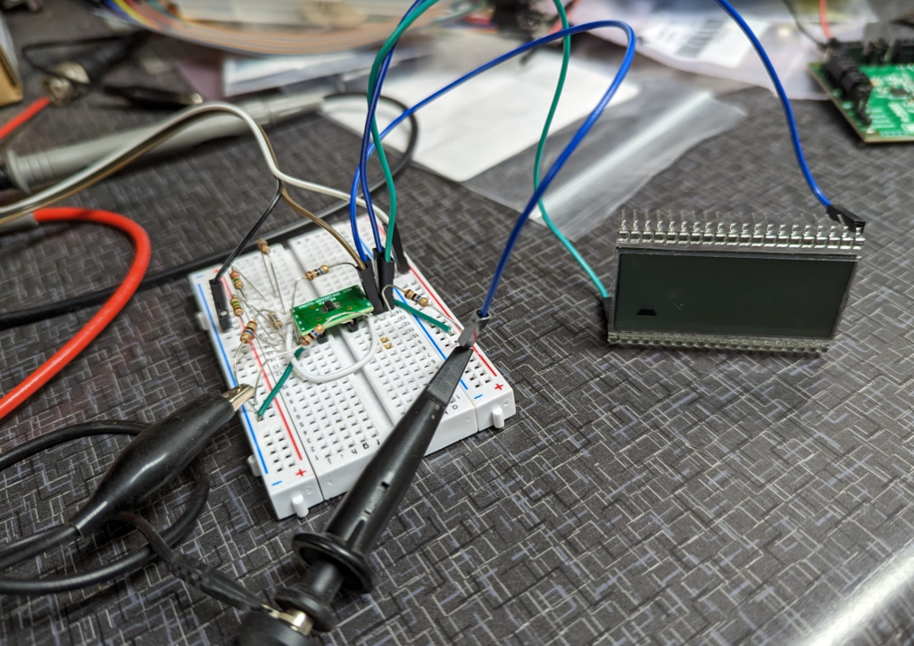
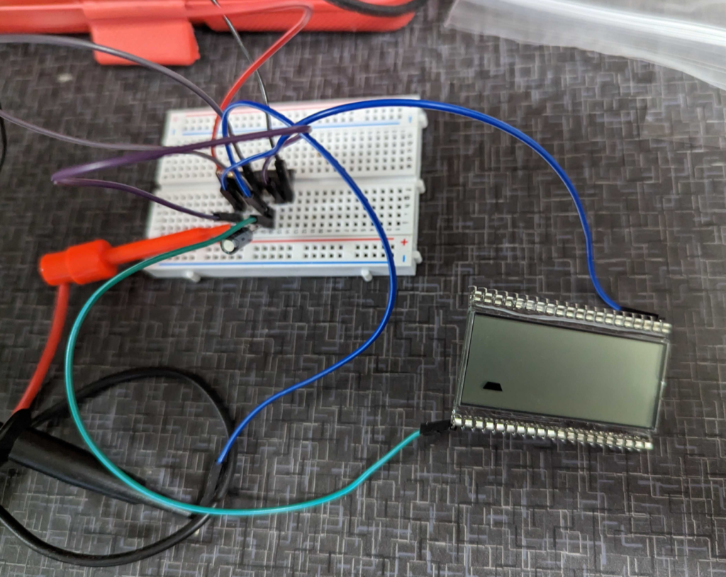
The design breadboarded up. It drives the screen!
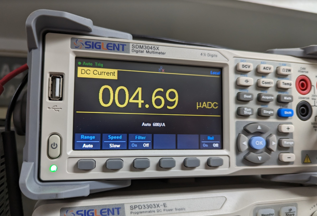
This is well under the resolution of my Siglent SDM3045X. Will have to wait to get the right equipment to measure the actual current the circuit is drawing.
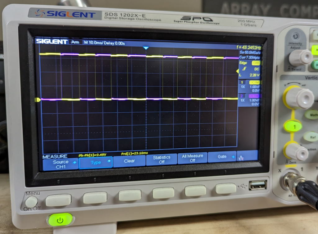
Here are the two output drive signals on the scope.
Next step to work on is the power retention system. The largest draw on the system right now is the leakage on the super capacitors! I found some super capacitors made by Eaton, HSL0814-3R8106-R, that specialize in having low leakage. Slightly higher ESR then some super capacitors but that isn’t that important for this project.
For the Cat Feeder Unreminder, I am going to pivot from using LEDs to indicate the “feeding” status and use a TN-Effect Display instead. These displays are much lower power then illuminated LEDs but they require slightly more circuitry to drive.
TN LCDs run off low AC voltage from around 3VAC to 6VAC depending on the screen. The one I picked, Varitronix‘s VI-422-DP-RC-S, operates over this range. They are not particular picky about the quality of AC voltage, just that it has zero DC offset. Driving the displays with square waves seems common. Anything north of 50Hz should do as well.
This application note from NXP shows how to drive these displays from logic level DC devices like microcontrollers.
Looking in my spare parts bin I found some old CD4049 hex inverters that I made into a simple RC based oscillator.
I used a 0.1uF capacitor and a 100K ohm resistor. Should get the oscillator to jiggle around 70Hz. Then I fed the output of the oscillator into another inverter on the CD4049. This gives me two square waves that are out of phase which will give us the AC voltage we need!
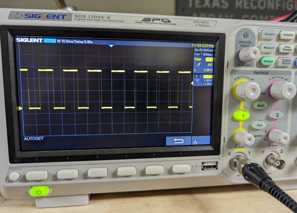
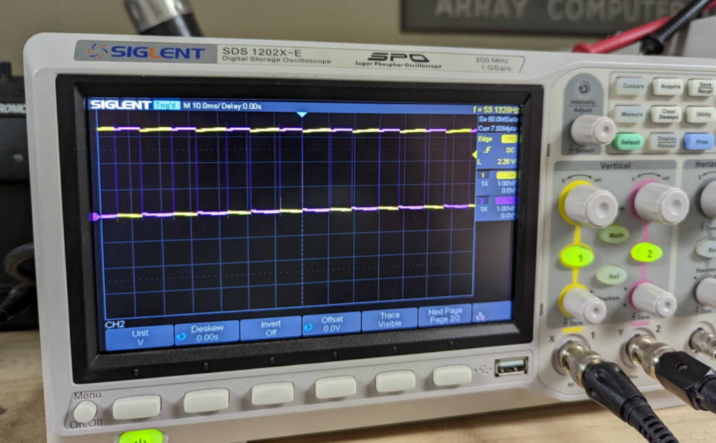
Circuit breadboards and driving the display. Spaghetti! Output of the Oscillator circuit. Ended up being 53Hz. Loose tolerance capacitor!Channel two in purple here shows the output of the out of phase signal that is generated from running the output of the oscillator into the inverter.
This works great! However the downside is this oscillator uses ~120uA at 3.3V without driving the Display. The display takes sub 5uA to drive so this is a big part of the power budget!
We will need another way to generate the AC voltage! Metacollin from the MacroFab Slack Channel suggested using a low power comparator in a relaxation oscillator configuration. This will get us to around 1uA in current draw if we use a MAX9019 dual comparator chip.
I am also looking for a way to measure currents that low. My Siglent SDM3045x is a bit out of its league at this point!
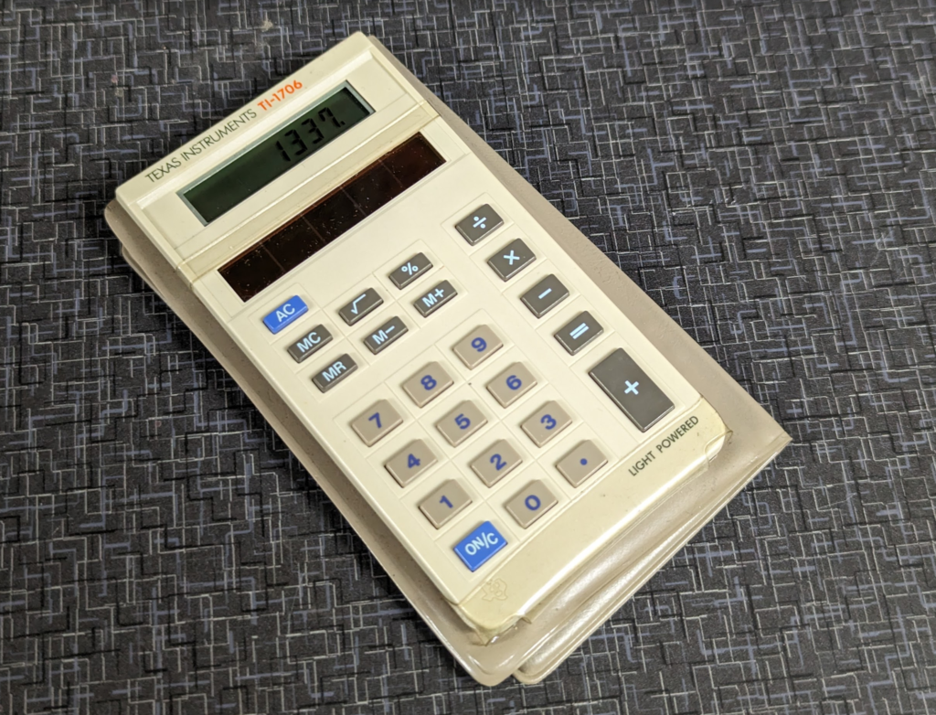
For the Cat Feeder Unreminder, I originally wanted to run LED indicators but I think it would be cool to run a reflective LCD display like on solar powered calculators.
For a display I was looking at Varitronix‘s VI-422-DP-RC-S. I was thinking I can hardwire the display to say FEED. What is weird with these displays is they run on alternating current (AC).
The solar power subsystem provides 3.3VDC which won’t work for activating the segments. Google searching around shows that these displays run on AC square waves. Initial thoughts are to make a push/pull transistor circuit that can drive and source high and the low side can sink giving us a 3.3V AC drive source.
But after chatting with some folks I think using a 4049 Hex Inverter like this will work great.
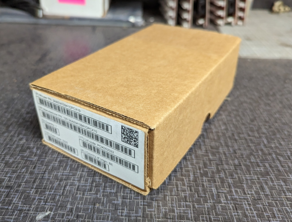
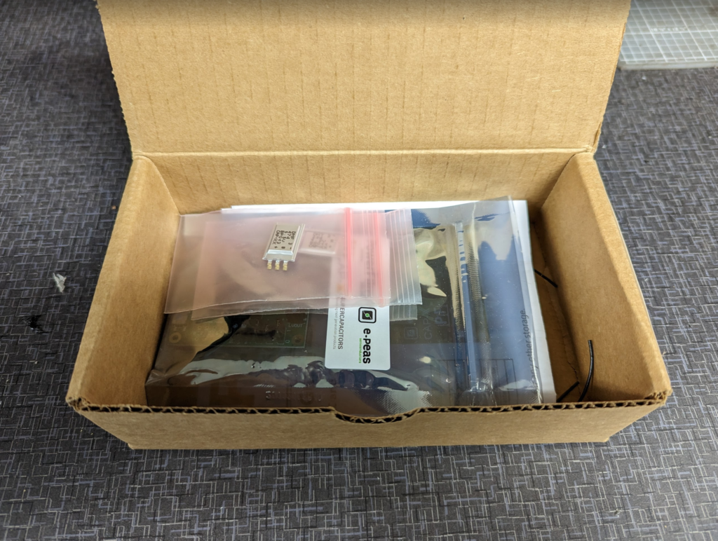
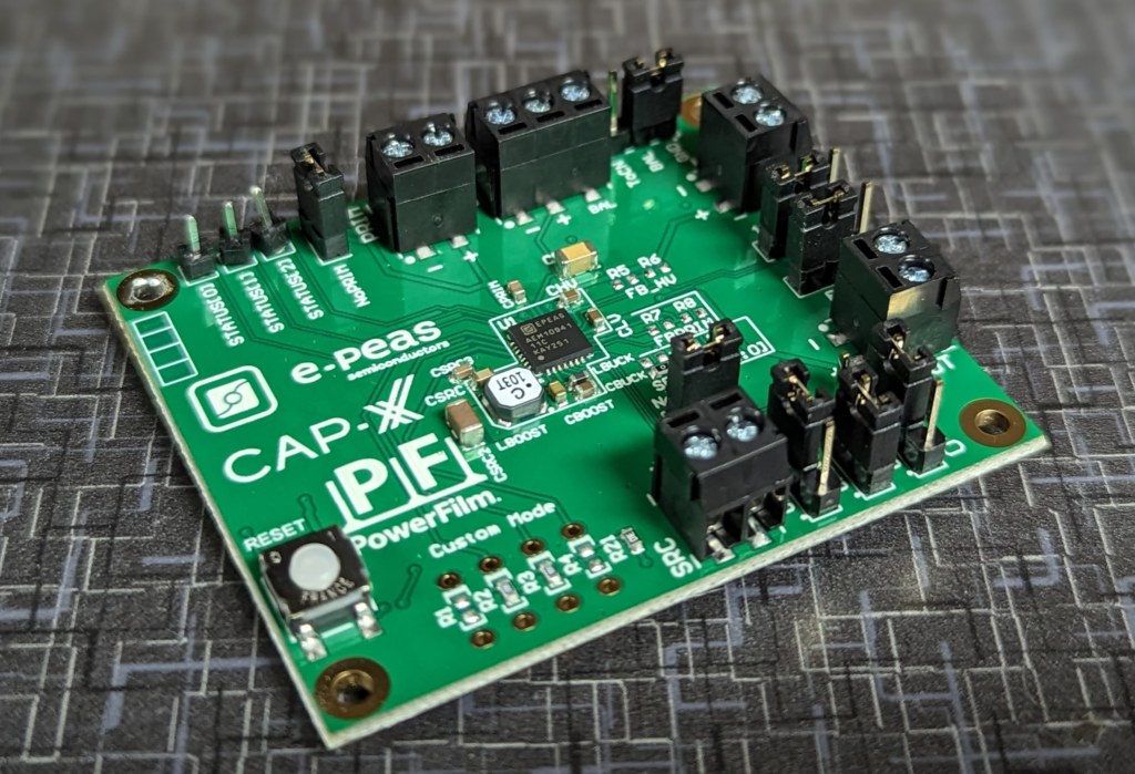
Received the 3AAEM10941CPCX10 evaluation kit for the AEM10941 solar harvesting chip today.
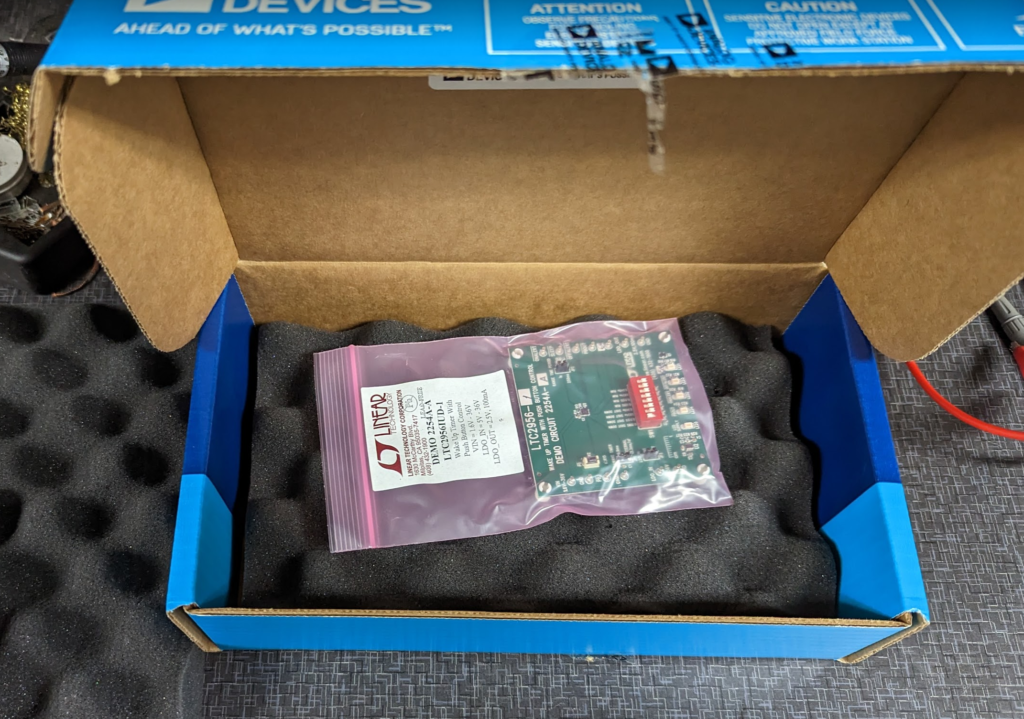
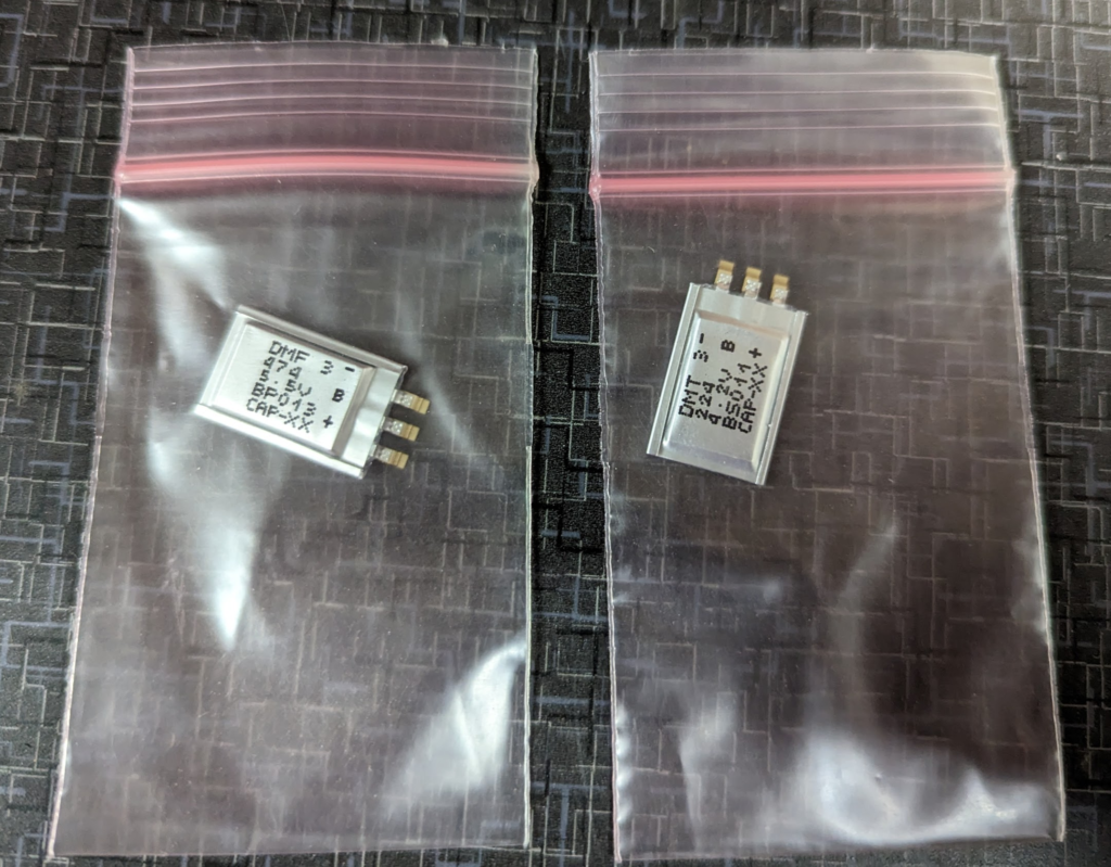
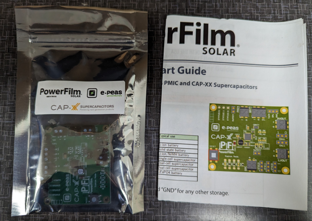
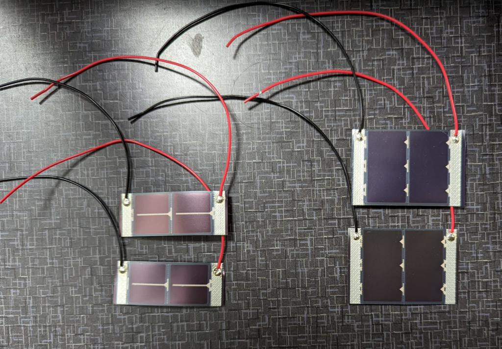
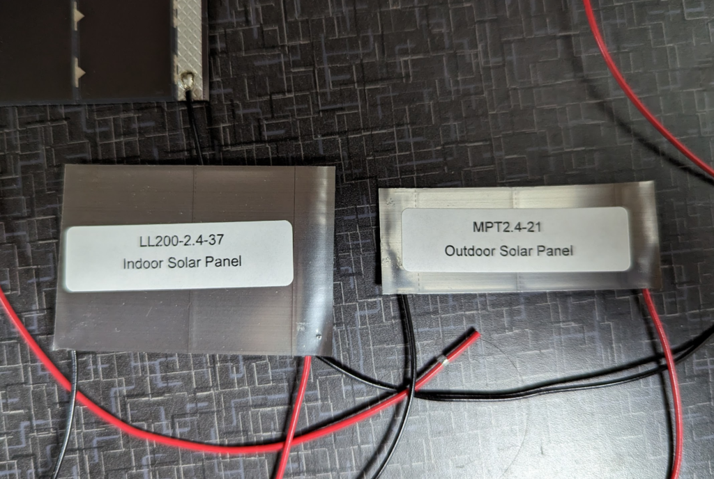
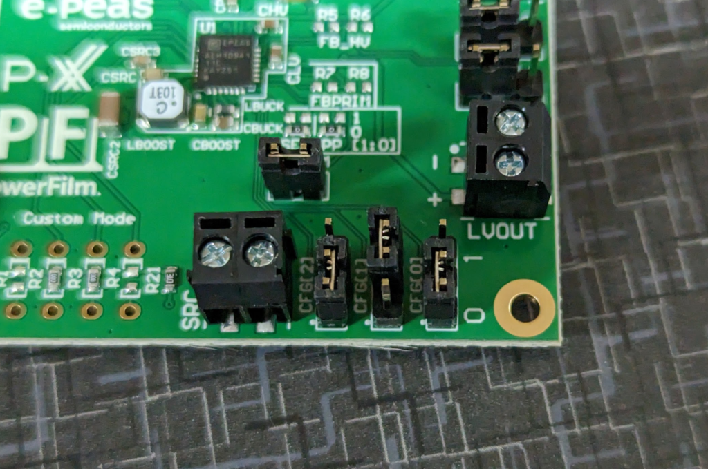
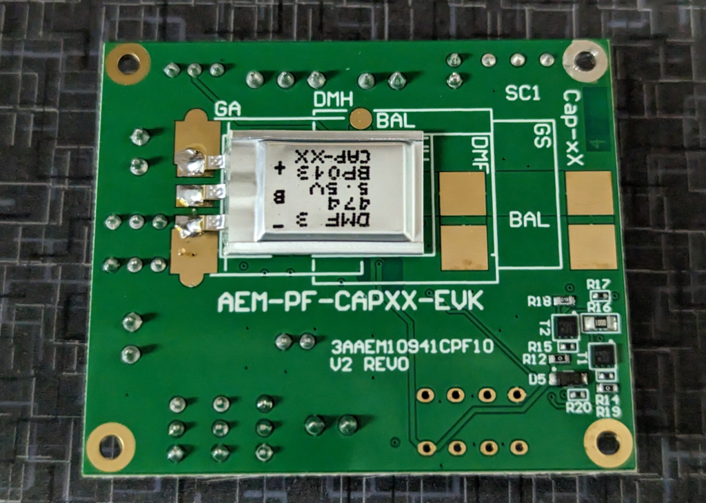
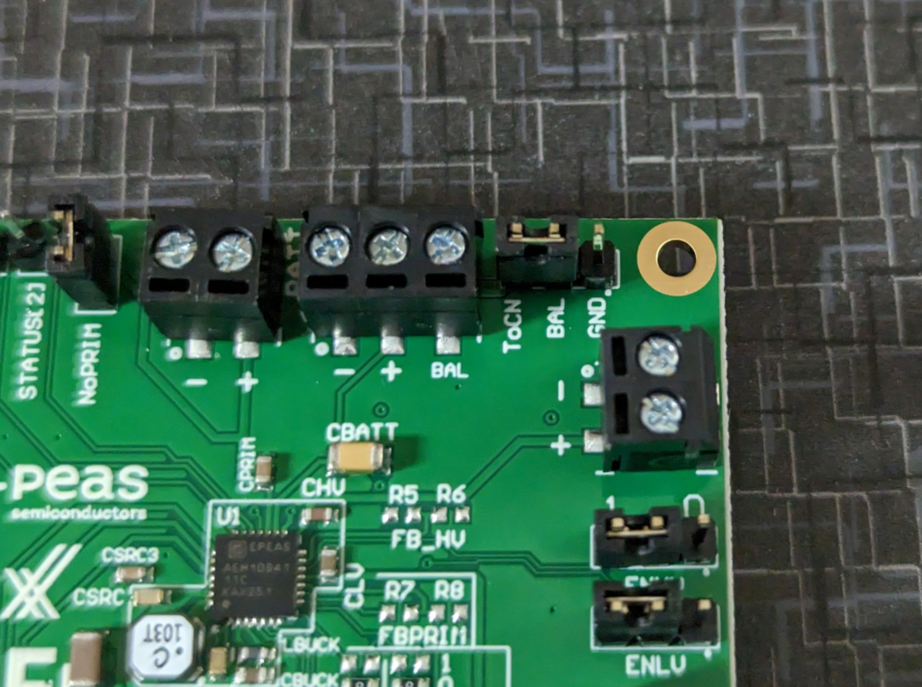
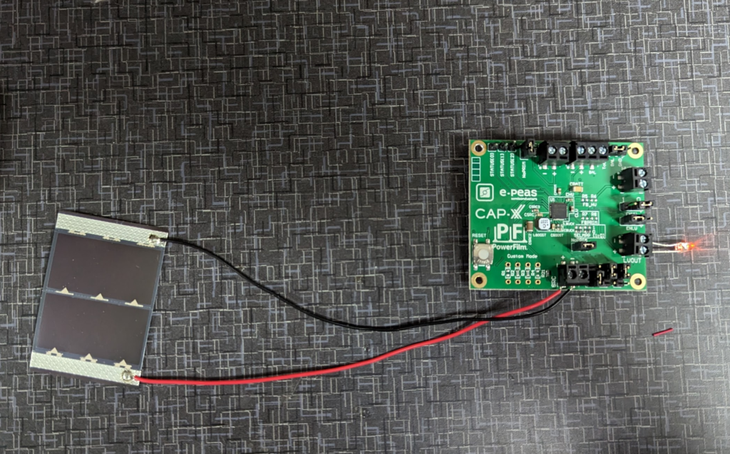
Box the kit came in. Surprised how “plain” the box is. Usually manufactures for evaluation kits have fancy boxes with branding on it so it can be viewed from the engineer’s storage shelf ;) .Inside. There was some bubble wrap I removed to keep everything from being shaken around.The super caps that come with the kit. Part numbers: DMT3N4R2U224M3DTA0 and DMF3Z5R5H474M3DTA0.The demo board and quick start guide.Two different kinds of solar panels. An Outdoor (smaller size) and Inside (larger size) type of panel. Part numbers for the solar panels are LL200-2.4-37 for the indoor panel and MPT2.4-21 for the outdoor panel. From the little bit I know about solar panels is that these are probably tuned to the light frequencies of there environment. The demo board. Quality of assembly isn’t the best. Jumpers are not soldered straight. Biggest one is the STATUS[2] pin on the upper right of the board. Also, the board’s jumpers are not set out of the box for the given example. Annoying to say the least. First step on firing up the the demo board is to set these CFG pins. Shown is how mine arrived. You need to set the jumpers to CFG[2] = 0, CFG[1] = 1, and CFG[0] = 1.Next, solder one of the super capacitors to the back side of the board as shown. I used the DMF3Z5R5H474M3DTA0 which is the larger of the two. Set the BAL jumper to connect BAL to ToCN. BAL is the balance pin of the super capacitor. These super capacitors are actually two cells in series and the balance pin is the connection between the two.Then attach the solar panel to the SRC terminal. To see if there is voltage output I put a LED across the LVOUT. The LVOUT voltage regulator is set to 1.8V which is below the forward voltage of the LED I chose.
Its possible it won’t light up right away. It takes sometime for the super capacitor to charge up. You can charge up the super capacitor with a power supply set to 3.3V and current limited to around 10-20mA. Make sure to not reverse bias the charging!
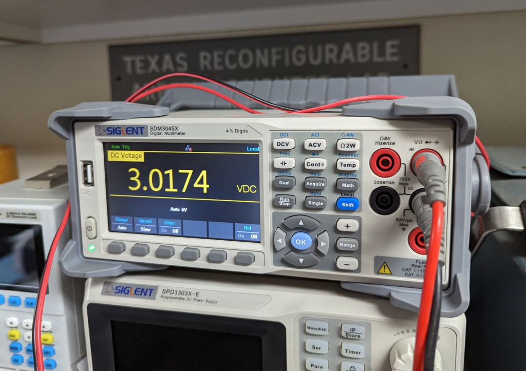
Voltage across the super capacitor while charging up off the solar panel!
The AEM10941 is a solar harvesting IC. It handles a small solar panel and charges either a lithium battery or a super capacitor. I ordered a evaluation board (part number: 3AAEM10941CPCX10) to test it out for the Cat Feeder Unreminder but I went ahead and made a footprint for it in Eagle. The evaluation board comes with a couple solar panels and some super capacitors to mess around with.
Its a small electronic device that makes sure you don’t overfeed your cat by feeding more often then needed. Low power consumption with no need of changing batteries or external power sources. Solar power? Basically a resettable egg timer that doesn’t need batteries cause if the batteries die then you won’t be reminded to feed the cat!
User interface should be simple. One button to reset the timer, then a LED that lights up when you are ok to feed the beasties and another LED that lets you know the system is working correctly. Maybe one led that is turned on when its not time to feed and then turns off when time to feed. Pressing the button resets and turns the LED back on? Verifying the circuit is still powered? Prevents hungry cats at least.
Simple BOM so far:
AEM10941
This is a Solar Energy Harvesting IC
DSF505Q6R0JBG
Super Caps
5F Capacitance!
Solar Panel AM-1816CA
84µA at peak power
This is specced at 200lx
LTC2956
Low power, configurable timer
Napkin math on power requirements. The LTC2956 draws 0.8μA. LED at 40uA. Total draw when Cat Feed Indicator is on is 40.8μA.
5F x (4.5V-3.6V) / 0.0000608 = 74,013 seconds -> 20 and a half hours!
So we have enough power from the fully charged Super Cap to run everything for almost a day. That is good. Should bump up the capacitance just to get a full day.