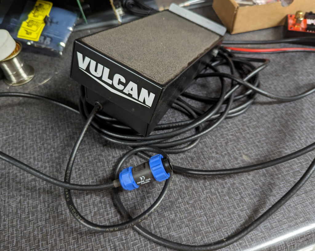
After chatting with Stephen Kraig on the podcast about hacking tig foot control pedals, I wondered what made the Vulcan brand foot pedal different. Most tig welding machines have either a 5 pin or 6 pin connector. Both of these types of foot pedals work the same. There is a simple SPST switch and then a potentiometer for how far the pedal travels. Farther the pedal goes down, the more amperage the tig welder will output. This requires 5 wires. The 6 pin connectors just have an unused pin.
The Vulcan Tig Welder (from Harbor Freight) has a 9 pin connector for the foot pedal! What do these extra pins do? Or are they just unused as well?
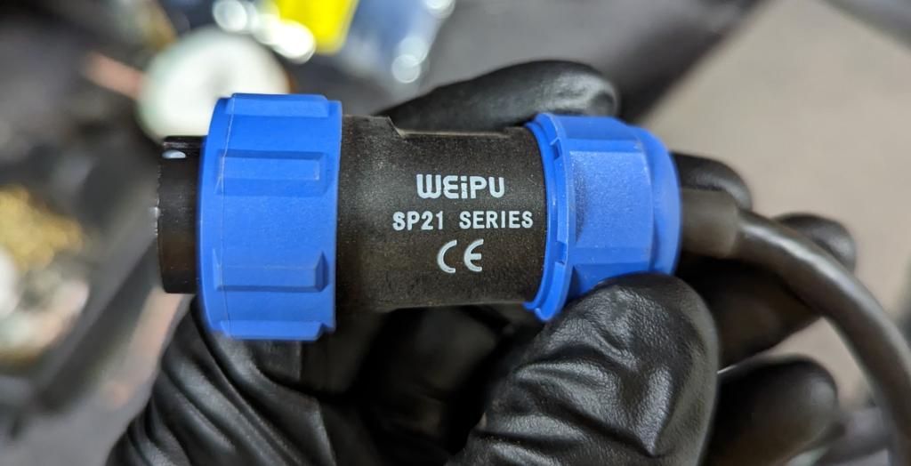
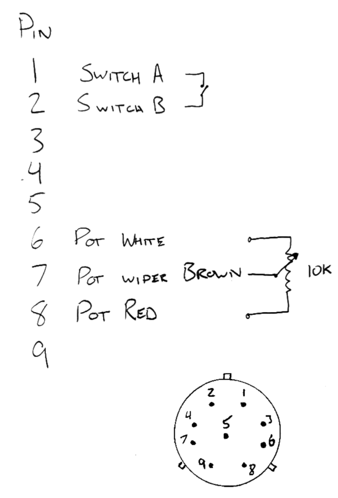
The connector is a Weipu SP21 series. Part Number: SP2110/P9 II 1. Looks like you can get these on AliExpress.
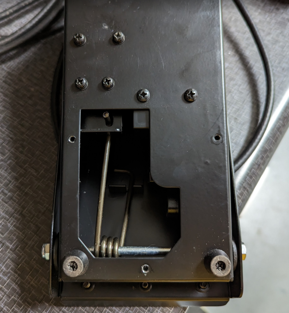
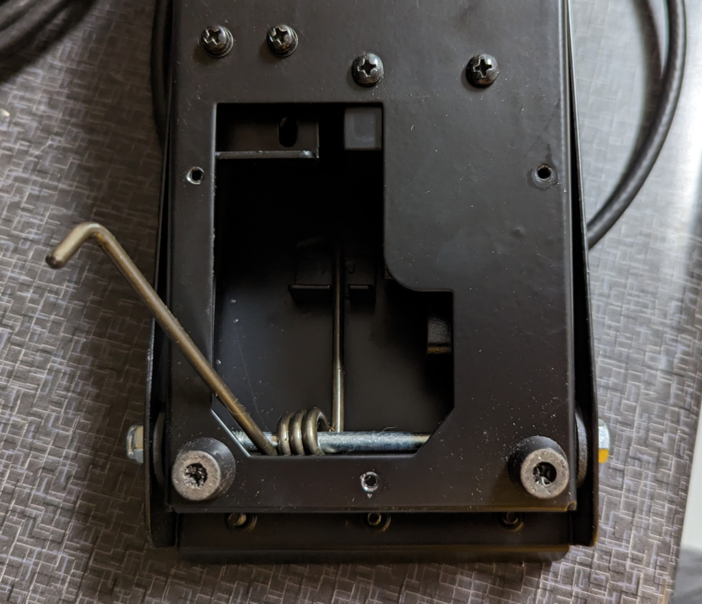
To open the foot pedal you need to remove this the panel on the bottom side with 3 screws. You will see the foot pedal spring inside.
The spring needs to be pressed down and unhooked from the bottom side (side facing upwards during disassembly).
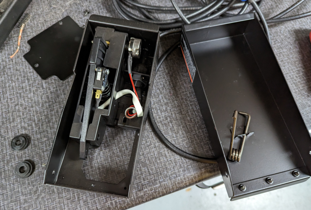
Then use a 10mm socket and wrench to remove the bolt used for the pivot and pull the case apart. There are two spacers on the bolt that locate the top part of the foot pedal with the bottom side along the pivot bolt.
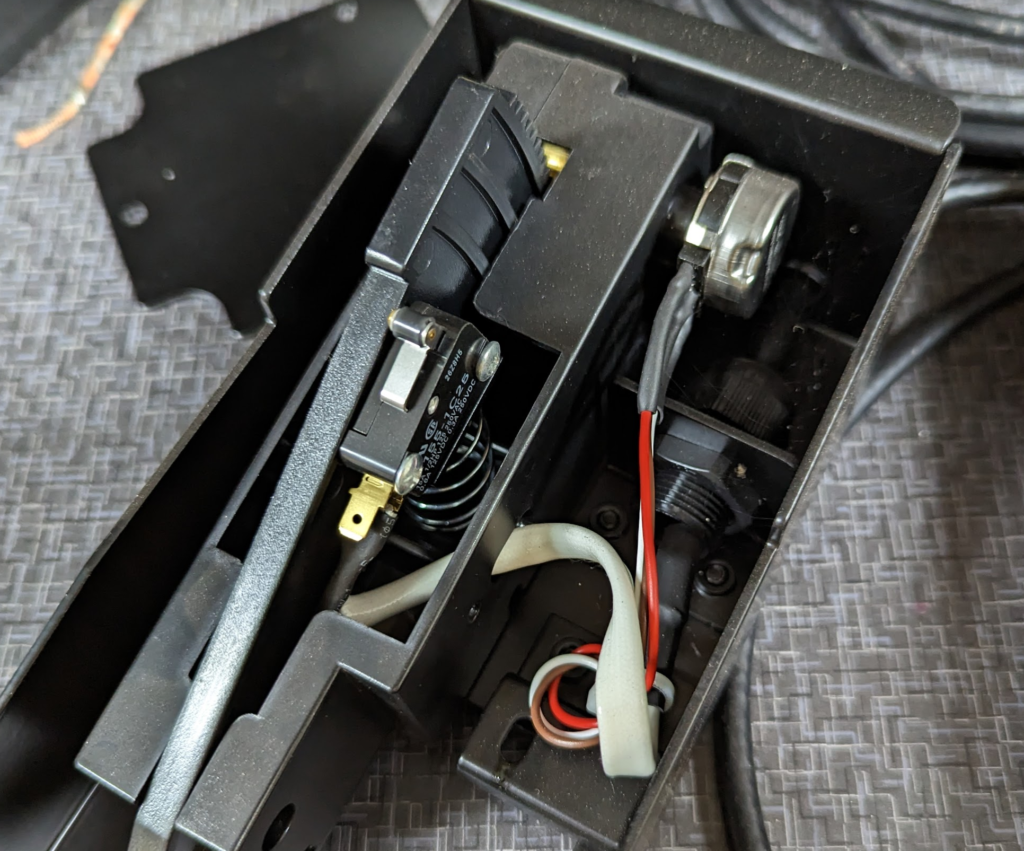
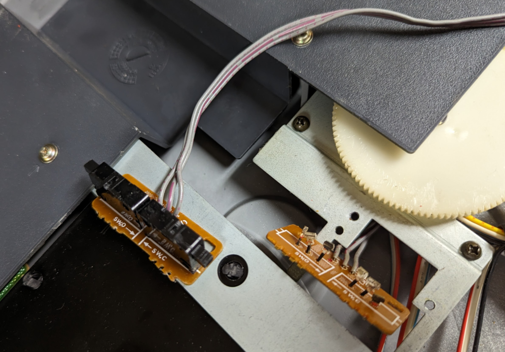
Inside the pedal we have a microswitch and a single potentiometer. Only 5 wires. Why Vulcan specified a 9 pin connector is lost to me. Would be interesting to see if there are any connections to the other 4 “unused” pins on the welder side…
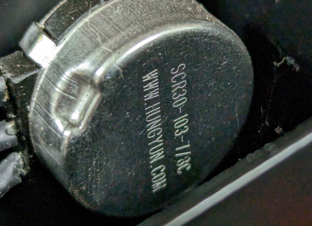
Potentiometer is a SCR30-103-7/8C by HungYun. 10K resistance.
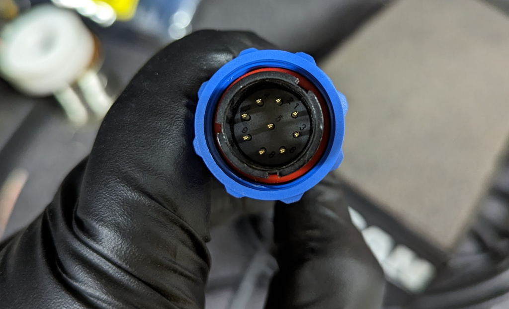
Here is a pinout for the connector.
I can probably get any finger controlled switch to work with this welder if its a 10K potentiometer.
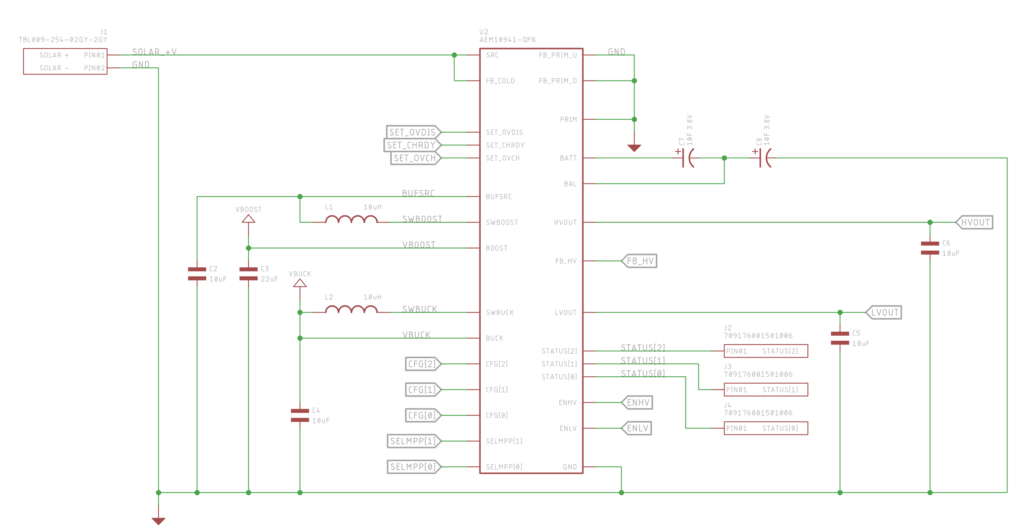
Just wrapped up the schematic side for the AEM10941 portion of the Cat Feeder Unreminder.
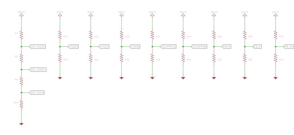
I broke out all the configuration pins to their own pullup / pulldown combos so I can experiment with voltage cutoffs for the super capacitors. Most likely leave most of configuration resistors unpopulated!
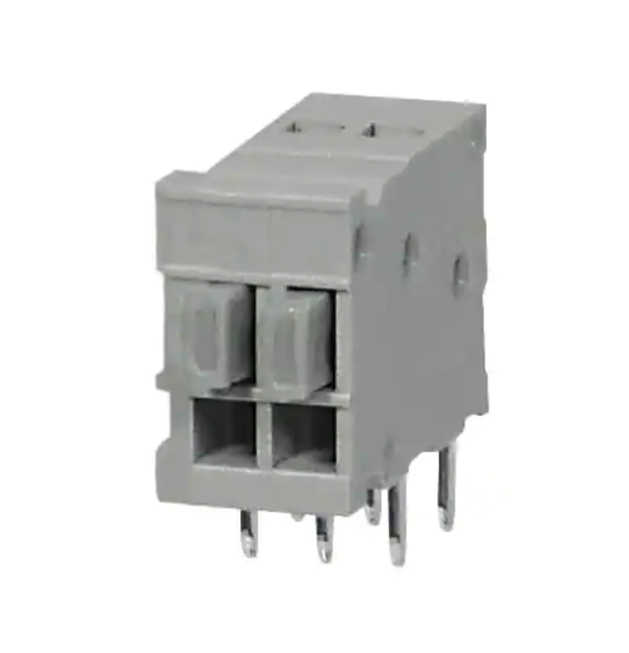
I found these really neat push button terminals that I am going to try to use for attaching the solar panel to the PCB. Part Number: TBL009-254-02GY-2GY
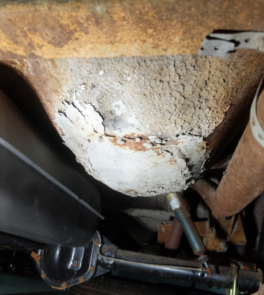
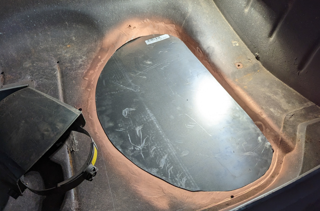
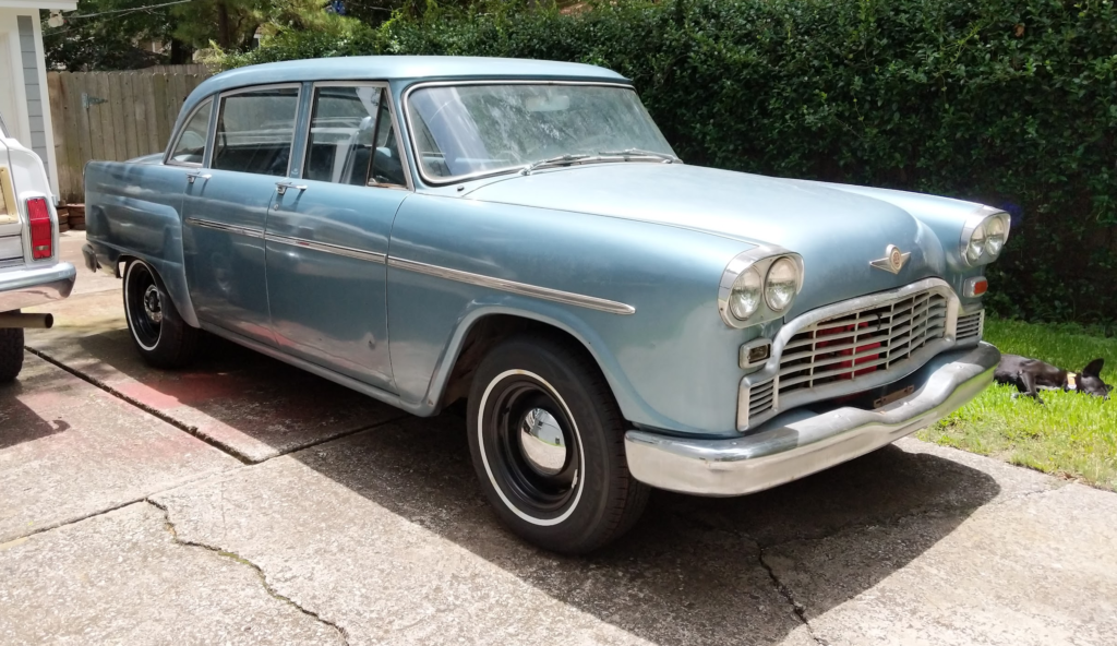
The “butt” cheek of the Checker is the spare tire well that is in the trunk. Mine was poorly repaired by a previous owner. Hammered metal to cover the rust holes and then slathered bondo over it. Bondo’d right over the dirt on the sheet metal as well. Awesome job previous owner.
I am not planning on carrying a spare tire (plug kit + tire inflator instead) so I want to remove this spare tire well and put the Checker’s battery and maybe a tool kit here.
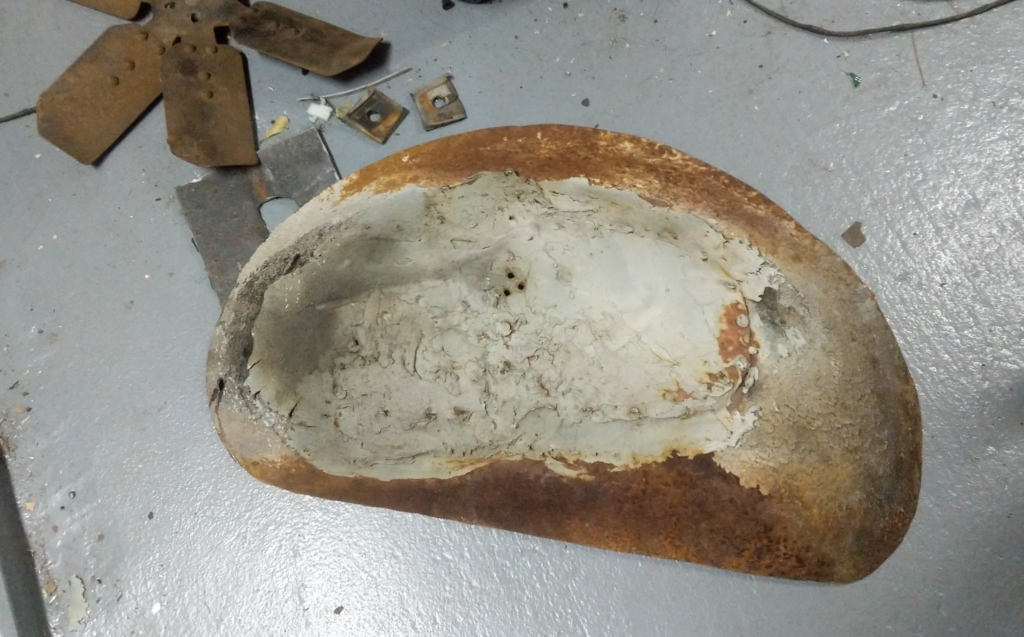
Cut out the old shoddy repair.
While cutting this out I found out that the entire trunk is skimmed with bondo… Wonder how much of this car is bondo now D:
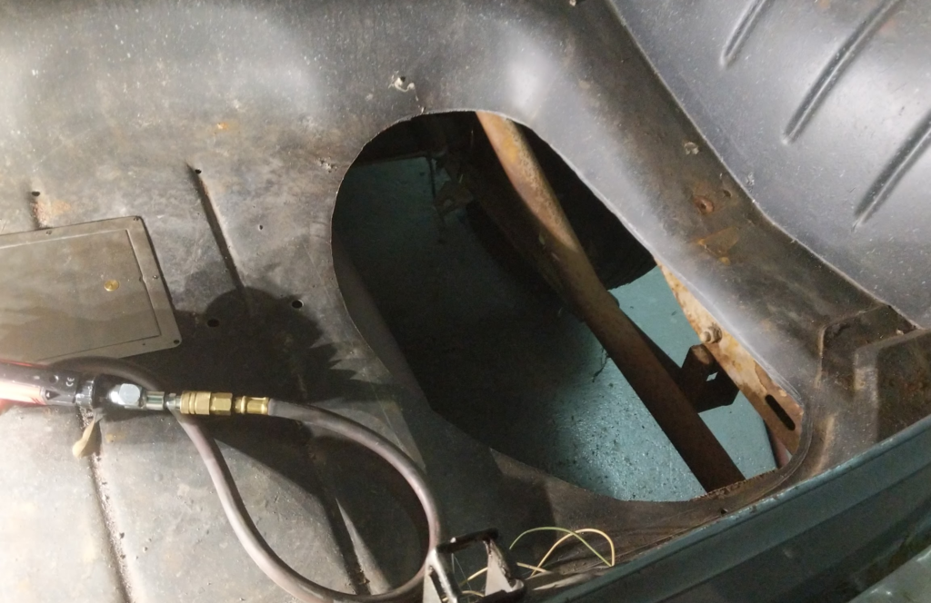
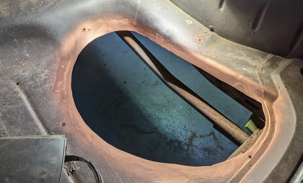
Then prep the area for welding.
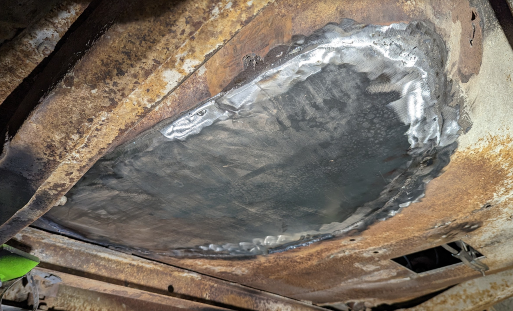
Use the removed part as a template in some fresh 18 gauge steel.
Fitment is ok…. I don’t have a lot of experience doing sheet metal fitment. Kinda learning as I go.
Used 0.023 wire on my mig welder. Here is the bottom of it after grinding.
I haven’t finished the top side of the welding yet. Bottom side needs a bit more work as some parts a bit too then for me.
I definitely need more practice welding thin sheet metal.
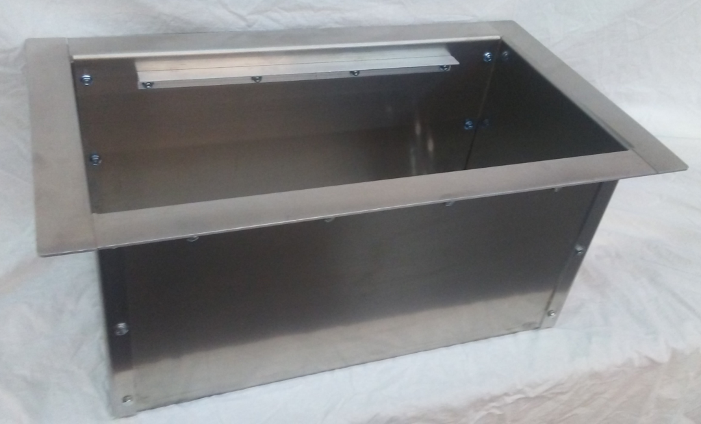
Once I finish welding this patch in I will then design a “flush” mount battery box that I can put in this spot similar to this.
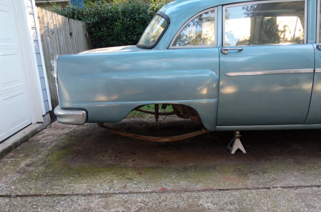
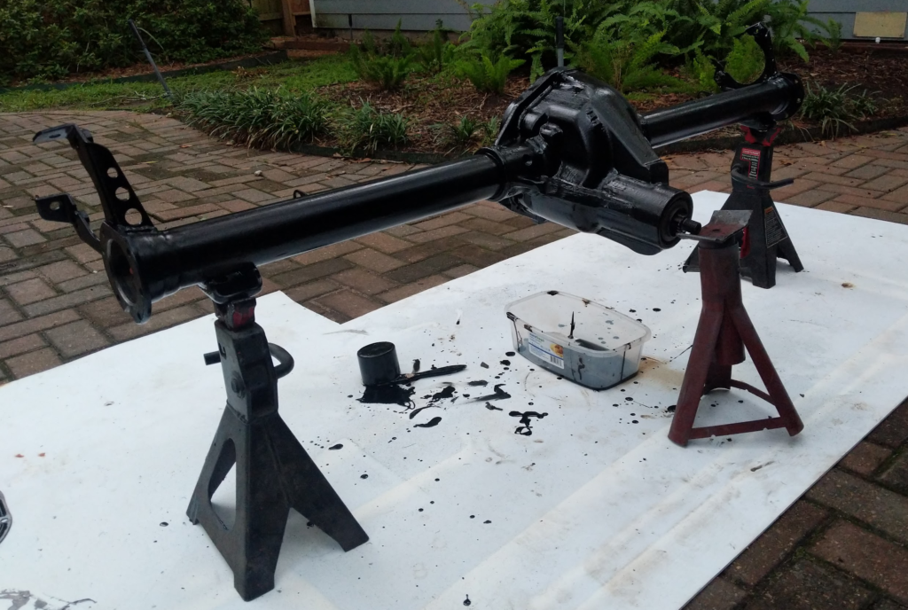
This post will be kinda in two parts: What I worked on with the rear end (suspension and axle stuff) on the Checker back around the time I bought it (2019/2020) and what I did today. Get caught up on documenting old work and then new progress!
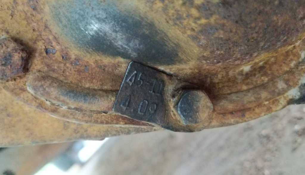
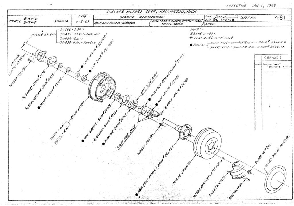
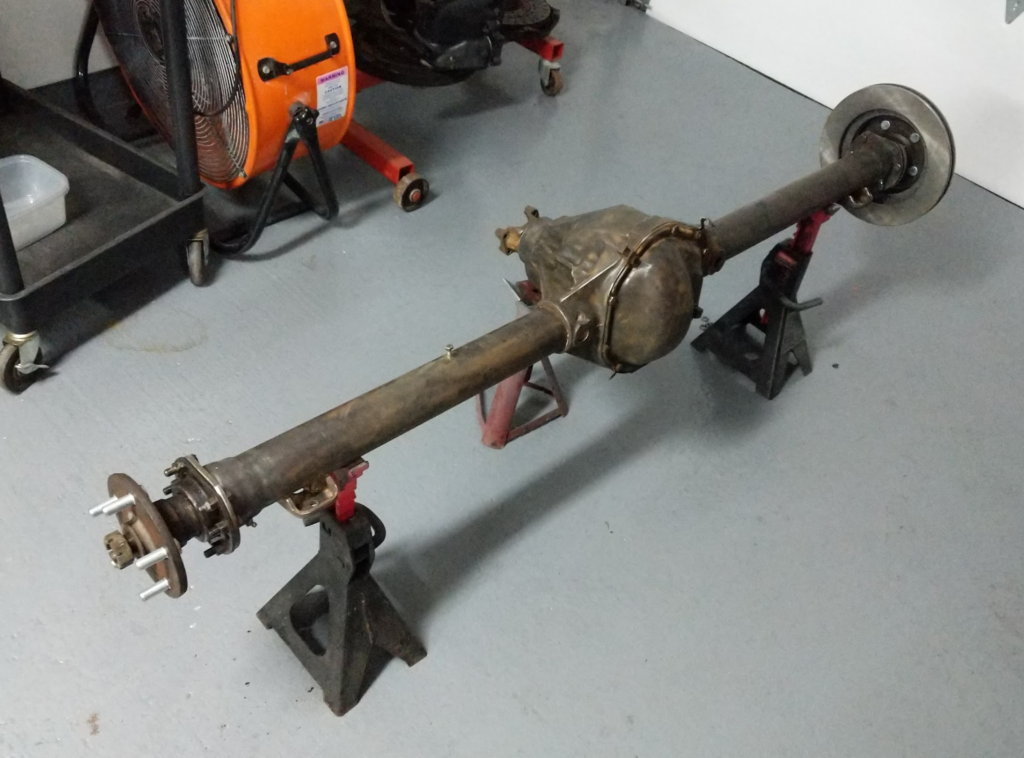
The rear axle of the Checker is a older Dana 44 with taper rear axle shafts, 4.09 gearing, and none adjusting drum brakes.
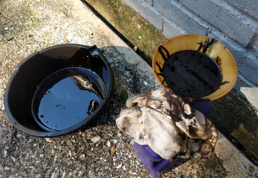
First step, drain the fluid…
60 year old gear oil. Yup smells as good as it looks. Then remove the axle from the rear of the checker.
Then start stripping down the axle.
This is just nasty.
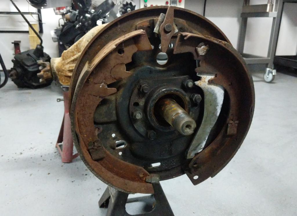
Removing the old brake parts.
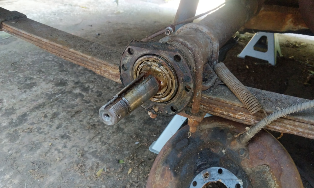
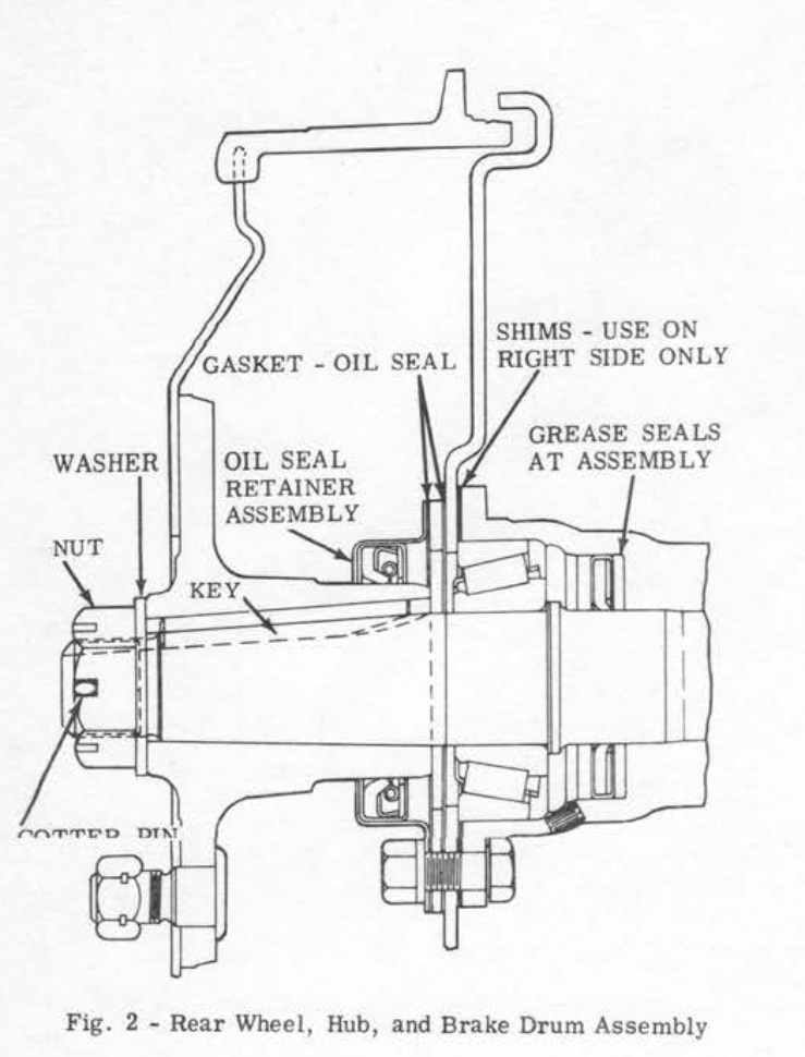
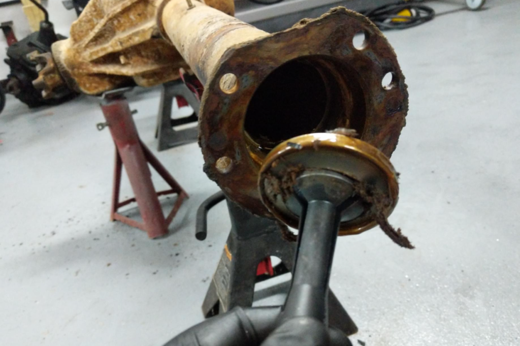
Pulling the axle seals. Goopy old “gold” grease. There are two seals here.
An outer seal that seals on the hub spindle and then an inner seal to keep the bearing grease from mixing with the axle oil. Outer seal part number is TIMKEN 450083. Inner axle seal part number is TIMKEN 7245. Though Checker during this era was doing lots of mid year changes and my axle doesn’t quite line up with the engineering drawings. Best thing you can do is pull the seals and read the part numbers off them and measure them to find modern cross references.
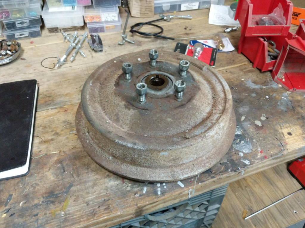
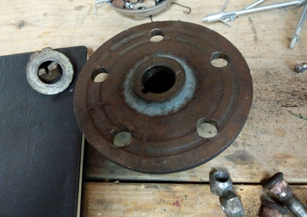
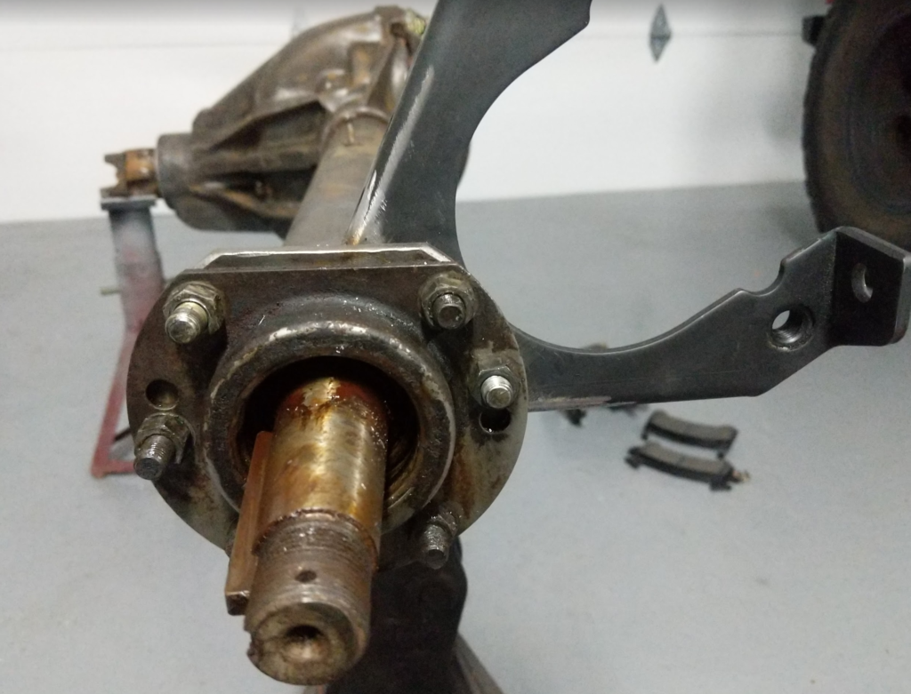
Then I wire brushed the entire axle and looked at converting the axle from the original drums to discs. To separate the brake drum from the hub I put the old lug nuts on and pounded out the wheel studs with a hammer.
After all 5 studs are removed the hub falls out of the brake drum.
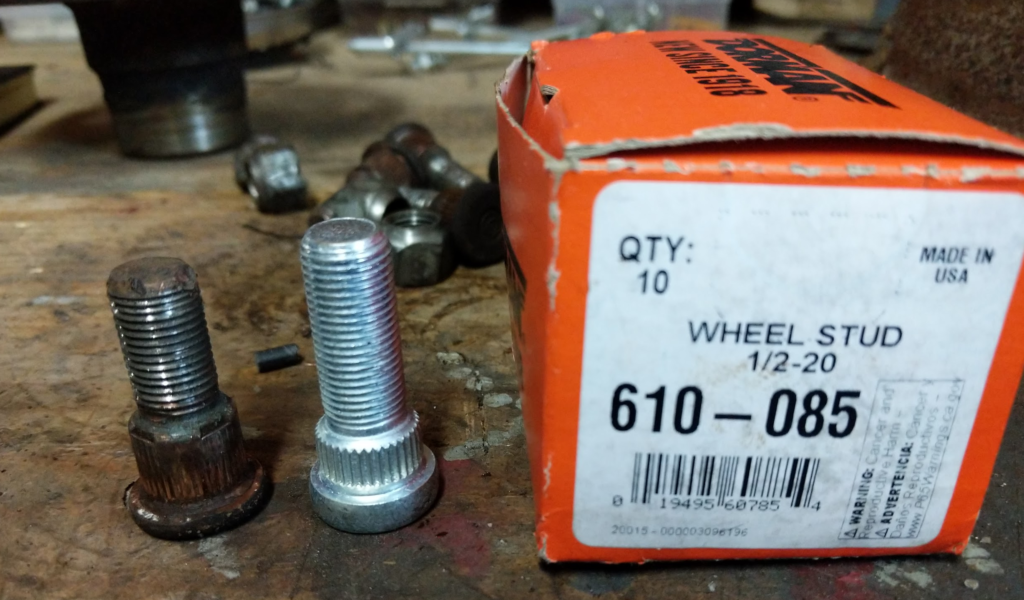
I measured the old studs knurl section and found some replacements that had a shorter knurl section and a longer threaded section. This is what you want to do for discs. You don’t want the knurl section of the wheel stud to go through the hub unless you want to press your discs to your hub!
Dorman 610-085 worked out great for my application.
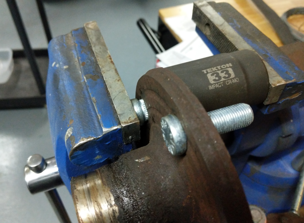
Press them in with a socket and vise. I should really get a proper press someday!
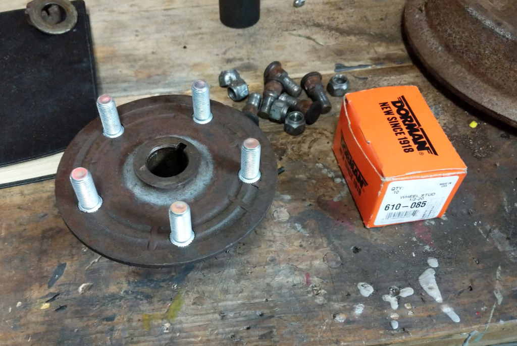
Here is one of the hubs completed. Note that the knurled part of the studs don’t go through the hub.
Mocking up the discs. For the discs and calipers I went with the following parts. These are the kind of calipers that have a built in parking brake lever.
Discs: Speedway Motors #91031039
Calipers: Speedway Motors #91603059
Brackets: Speedway Motors #91641010
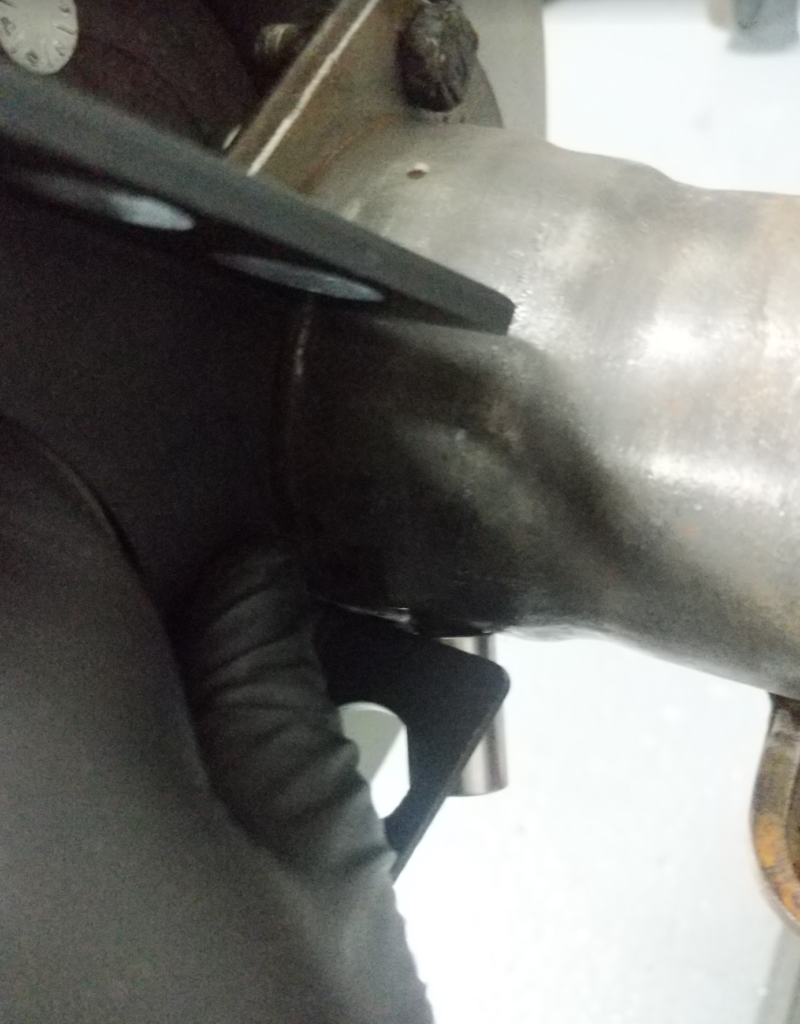
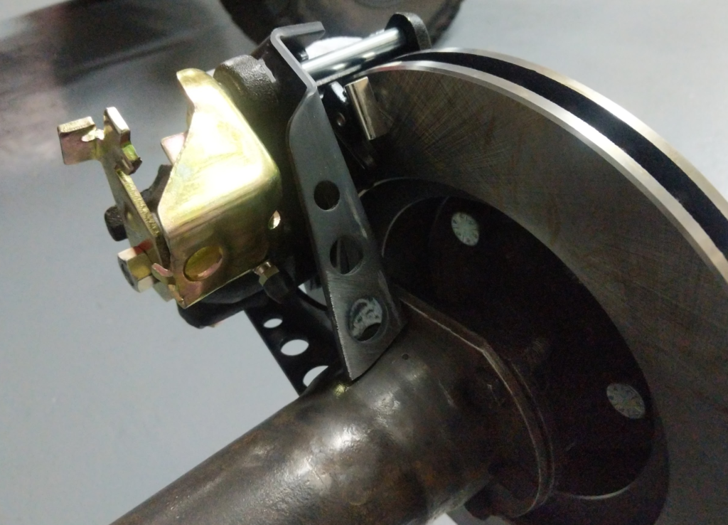
Seeing how the bracket will weld on.
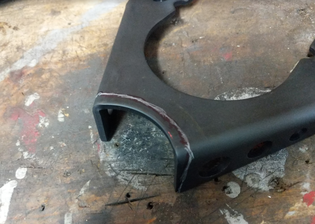
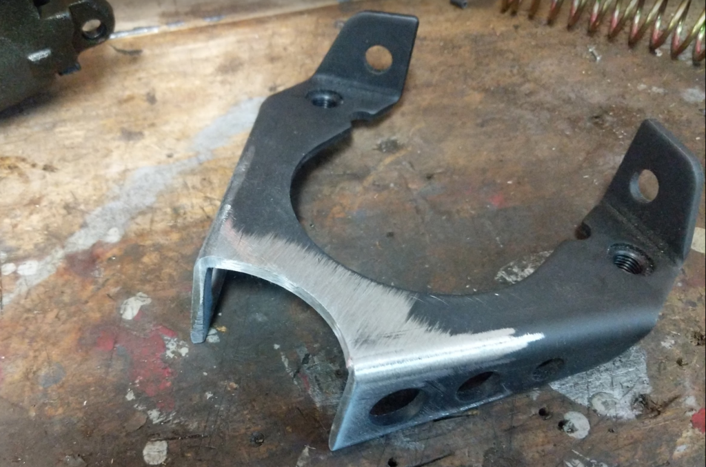
Trimming the bracket to match the axle housing.
Prepping for welding.
Getting the bracket in the right spot by mounting the caliper and disc.
Tack the bracket in.
Before final welding I drilled out the bracket where the bearing retainer bolts had to pass through the bracket and then welded it up.
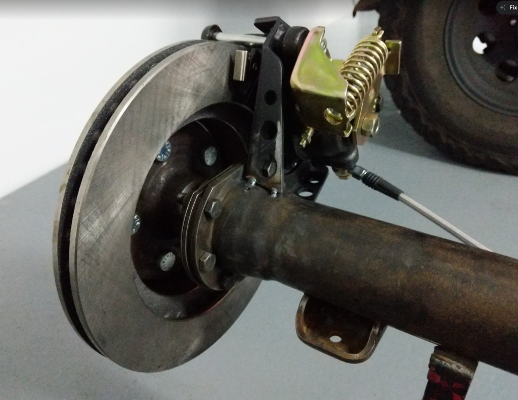
Routed some brake lines with p-clips.
Then gave it a nice coat of paint.
Then I reassembled the axle and put it back under the Checker… to forget about since I decided to work on my Red Jeep instead of the Checker.
Thus, the Checker sat for 3 years before I have been getting back to working on it.
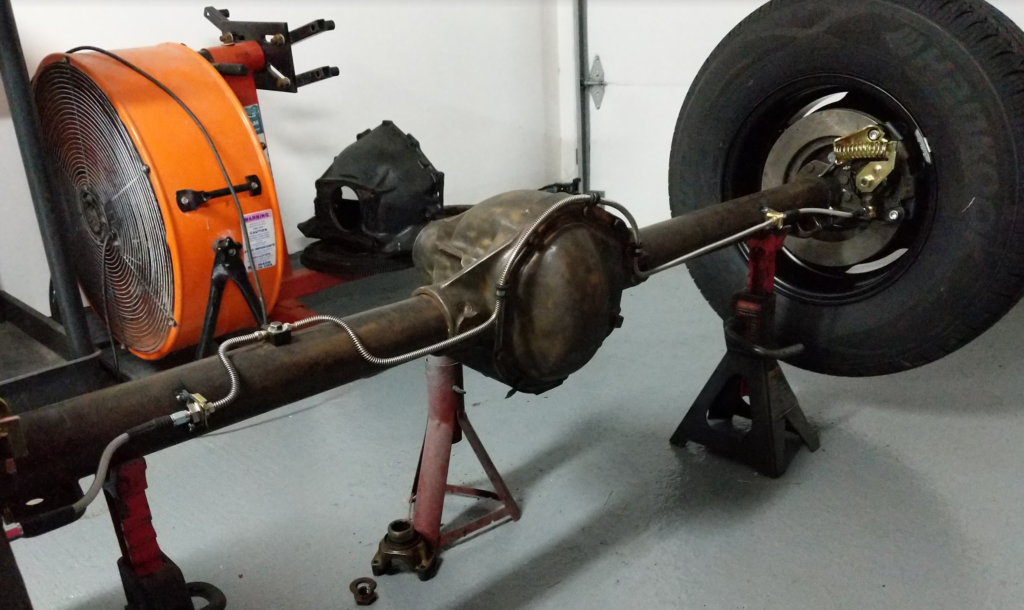
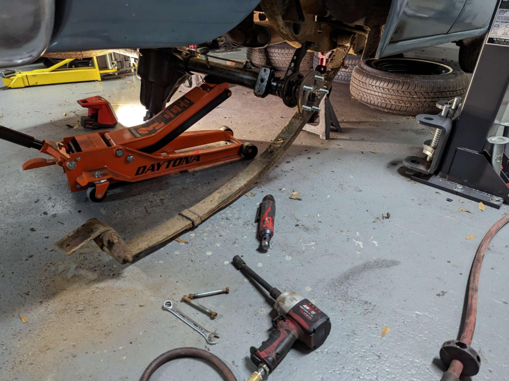
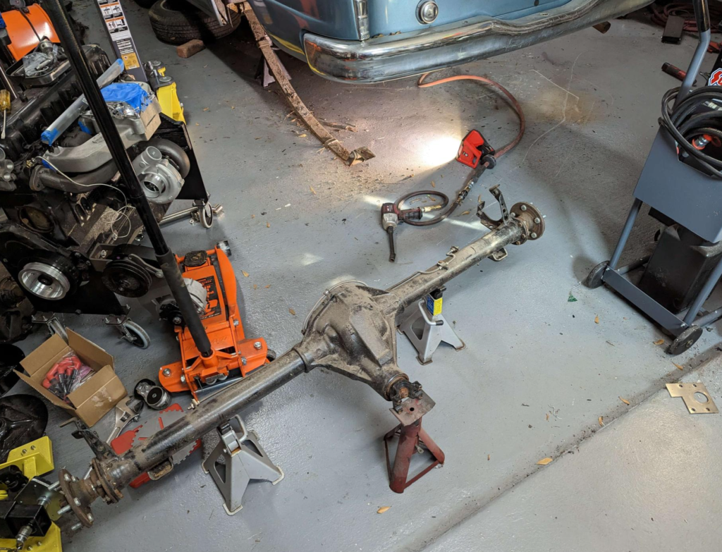
Today, I pulled the axle back out to finish up the rear suspension and axle work. One of the problems with the axle was that the brake lines interfered with the shocks. Will have to move the brake line brackets…
Pulling the rear leaf springs out.
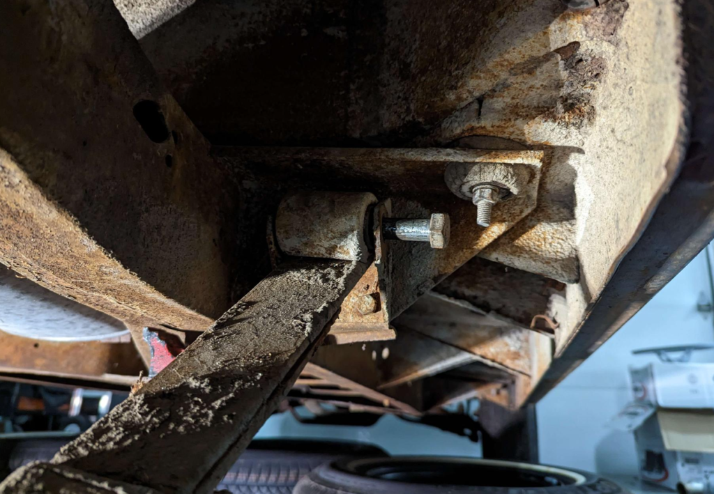
The front leaf spring bolt can’t come out without removing this body bolt… and the body bolt was rusted solid and just spun in place. Nothing a little application of a sawzall can solve!
Axle removed once again after 3 years. Amazing how dirty it became just sitting in the driveway!
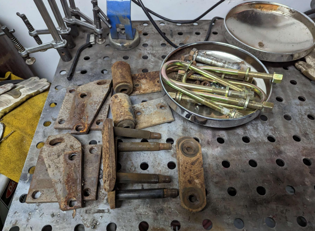
Here is all the leaf spring hardware that I will be refurbishing. The plan is to vapor hone the parts and then zinc plate them. The U-bolts are “new” from 3 years ago. Part number: Calvert Racing U-Bolts UR275X70. I remember it being kind hard to find some u-bolts that matched the originals in size.
U-Bolt Length (in.): 7.000 in. U-Bolt I.D. Width (in.): 2.750 in. U-Bolt Diameter: 0.500 in.
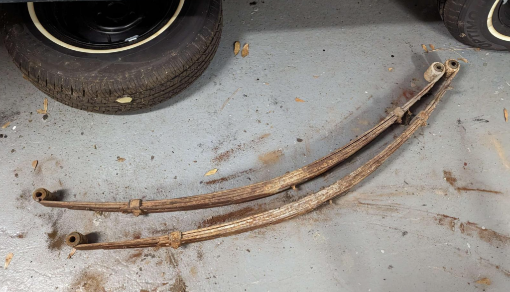
These are the springs. Besides the bushing and appearance they are in good shape. I will try to refurbish these. Clean them up, new paint, new bushings. Should be good to go?
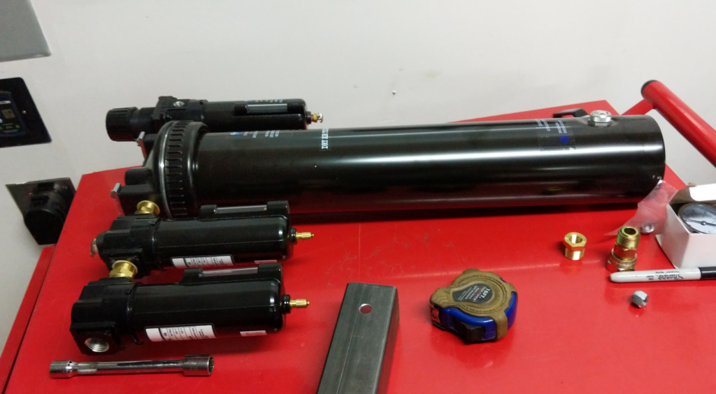
For my garage/shop air compressor (Ingersoll Rand SS5) I wanted to setup a inline dryer and hose reel so I could use it all around the garage and still use the same hose when I needed to spray paint and sand blast (these require dry air).
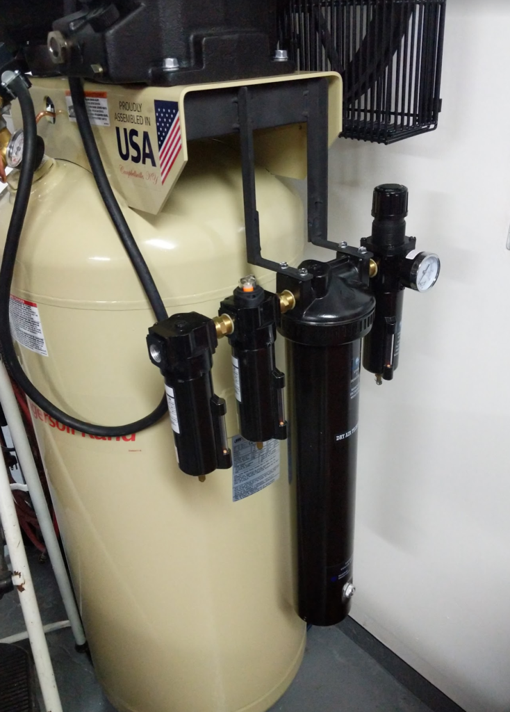
This is the air dryer system I ordered, an Arrow Pneumatics PC7612XXL. It has an oil separator, water separator, desiccant air dryer, then a pressure regulator.
Problem is mounting it. There isn’t a lot of room in the garage on the wall for the air dryer system. What about mounting it to the air compressor itself and use up some old scrap steel material in the process?
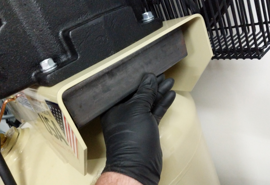
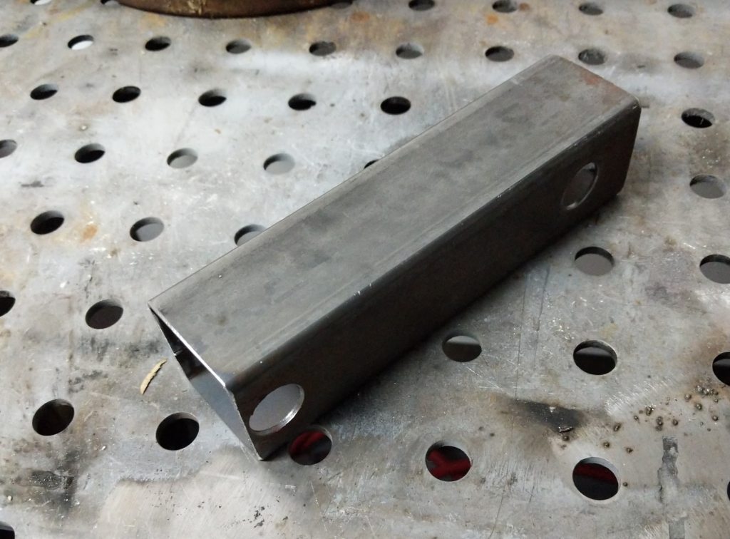
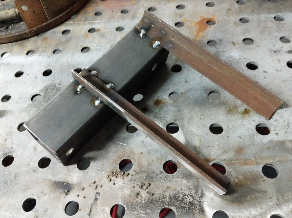
Mock up the main bracket out of some 2″ box tubing.
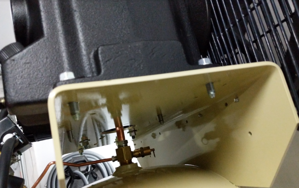
The bolts for the compressor unit has enough thread to put on a nut? Will attach the bracket here.The large holes are so you can fit a socket from the bottom side of the bracket to attach a nut to the bolts on the compressor.
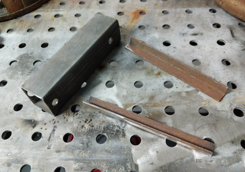
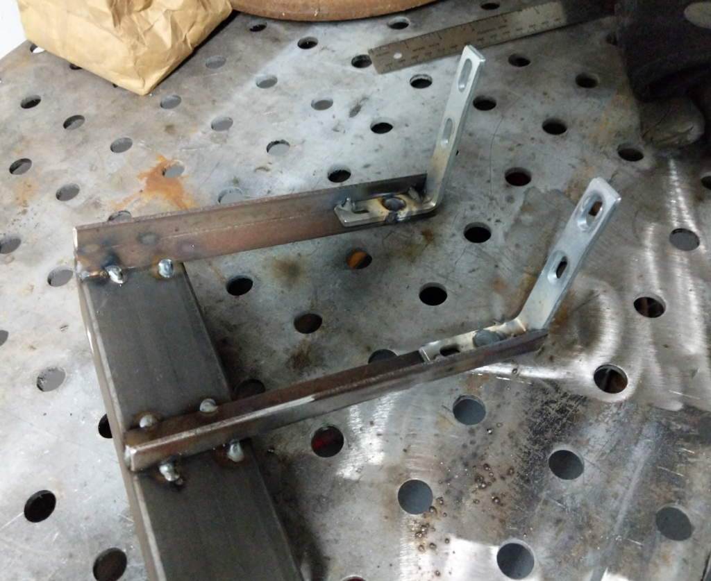
The air dryer system came with some little brackets that you can mount the desiccant dryer part of the system to for a wall mount. Welded these with the correct spacing to the bracket.
Add some black primer paint and bolted on.
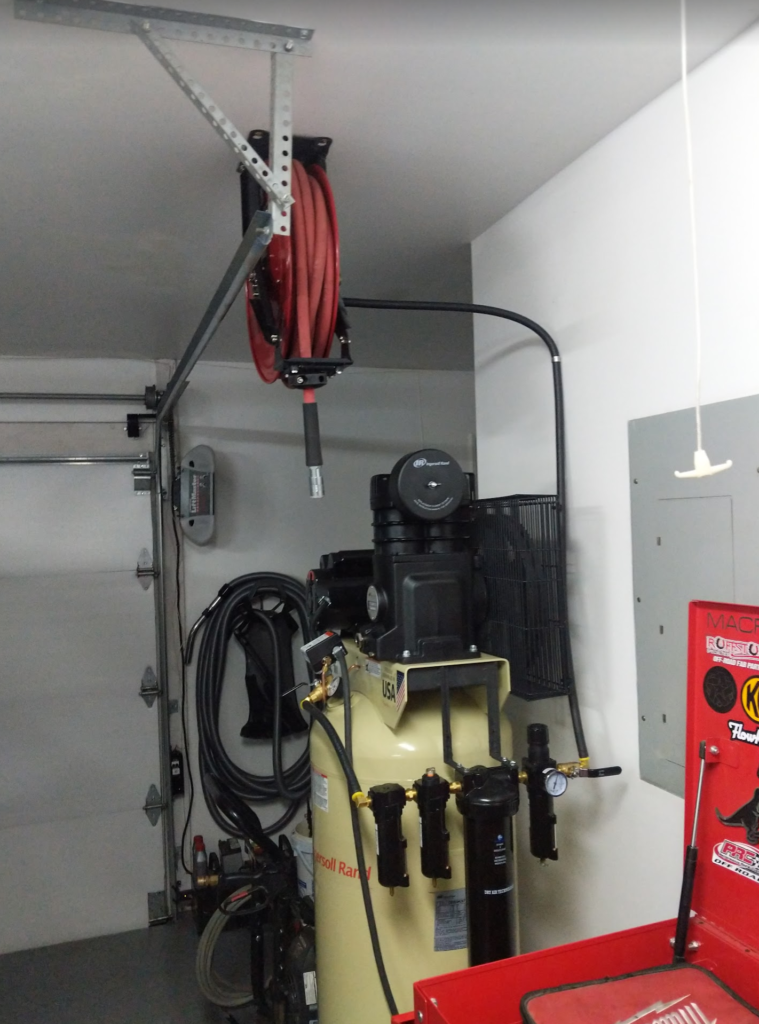
Here is the entire air compressor system with the hose reel.
The hose reel is TEKTON 46878. The system is plumbed with Thermoid Flex-Loc hose and fittings. On the end of the hose reel I am running large Milton (S-224) G-Style couplers for maximum flow. Then I have two 3 foot long leaders that connector the G-Style Coupler and adapt them to the standard D-Style couplers.
Why two leaders? Or why leaders in general? One leader is just a straight pass through. Used for running tools that require clean, dry air like blow off guns, paint sprayers, sand blasting, and tire filler. The second leader has a Coilhose Pneumatics 40014 In-Line Lubricator for tools that require oil.
The leaders also reduce wear on the main 1/2″ hose in the reel. The last couple feet of the hose is where the hose gets twisted up and abused. Easier and cheaper to replace a leader then have to replace or splice the main hose.
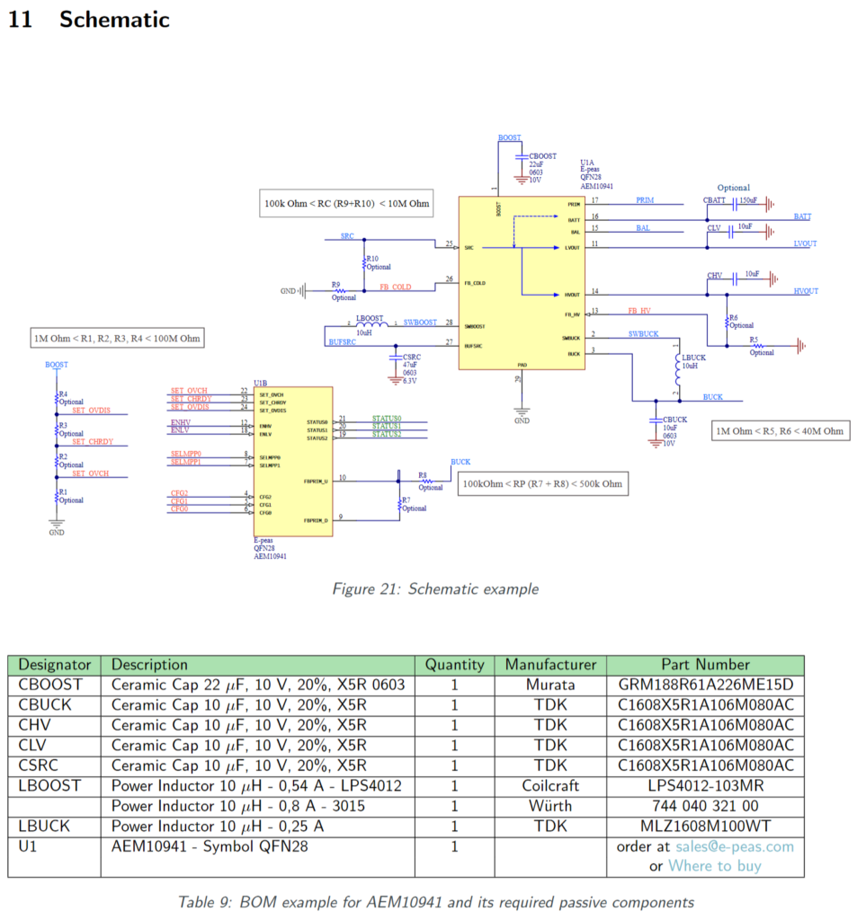
For the Cat Feeder Unreminder, the AEM10941 “ambient energy manager” has built in boost and buck regulators. These need external components like capacitors and inductors to function.
The example schematic in the datasheet for the AEM10941 looks like this and has these recommended components.
Schematic from the Datasheet for the AEM10941
The capacitors are just your standard 0603, which are kinda small for the values. My project can handle larger sizes which will net better performance and lower leakage current.
For example GRM32ER61A106KA01L (10uF 10V X5R 1210) vs GRM155R61A106ME11 (10uF 10V X5R 0402). While its hard to specify leakage current as it varies with voltage, temperature, and frequency you can look at the insulation resistance and the larger the package the larger the insulation resistance.
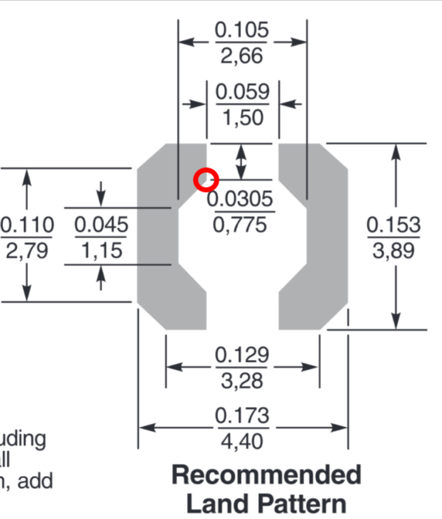
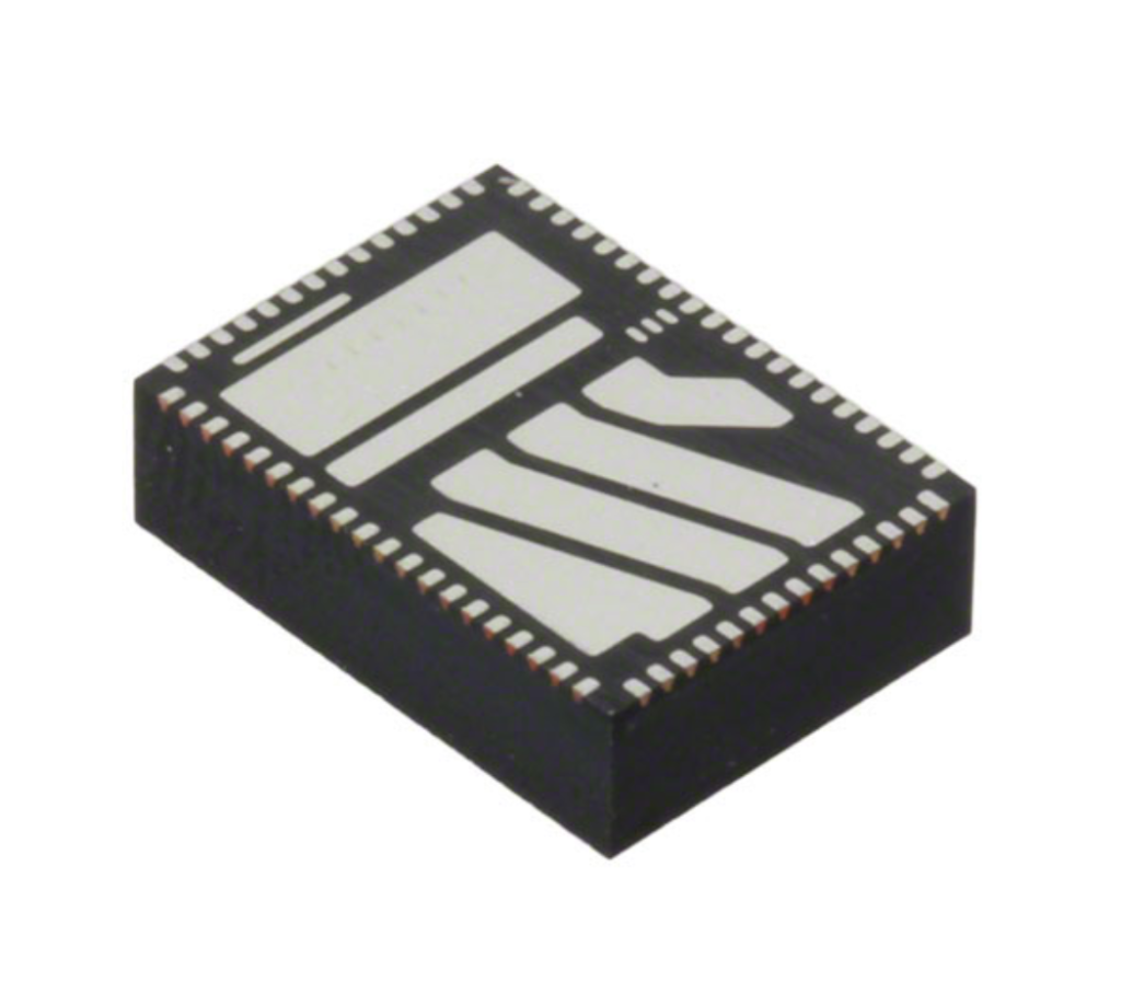
Anyways, enough about capacitors. The Coilcraft inductor the schematic specs is from the LPS4012 series. I didn’t have this family in my EDA tool already designed so I opened up the datasheet to this horror.
Land pad for the LPS4012 series inductor
This doesn’t look too bad but this showcases one of my pet peeves about how part manufactures dimension parts. Its pretty clear that mechanical engineers dimension parts. PCB Design tools don’t dimension like Mechanical Design Tools. In PCB tools, you typically specify the absolute location of the point/vertex of the line. This is different then Mechanical Design tools where you specify lengths and relationships between points.
For example look at this point right here that I circled in red.
For the EDA tool I use (Eagle) the only way to do this is to tell that point of that polygon is at point (-0.75mm, 1.17mm) assuming the center of the part is (0, 0). X is easy, 1.5mm / 2. Y on the other hand is (3.89mm/2) – 0.775mm. Again just some arithmetic, but this is where the problems occur on validating new footprints and having to spin a prototype again just due to a slip of math.
Part manufacturers either need to give the data in a way that makes it easy to translate into the tools the electrical engineer uses or EDA tools need to become more like Mechanical tools in how you parametrically associate line edges and dimension footprints.
The component EN2342QI, found on the CursedFootprint twitter account.
Now, I know that Autodesk has been working on bringing PCB layout design (and maybe schematic?) to the Fusion 360 ecosystem which would solve this problem. I don’t know how far along that product is but I should look into it for the next board I design. If Eagle libraries can be ported over then that would be rad.
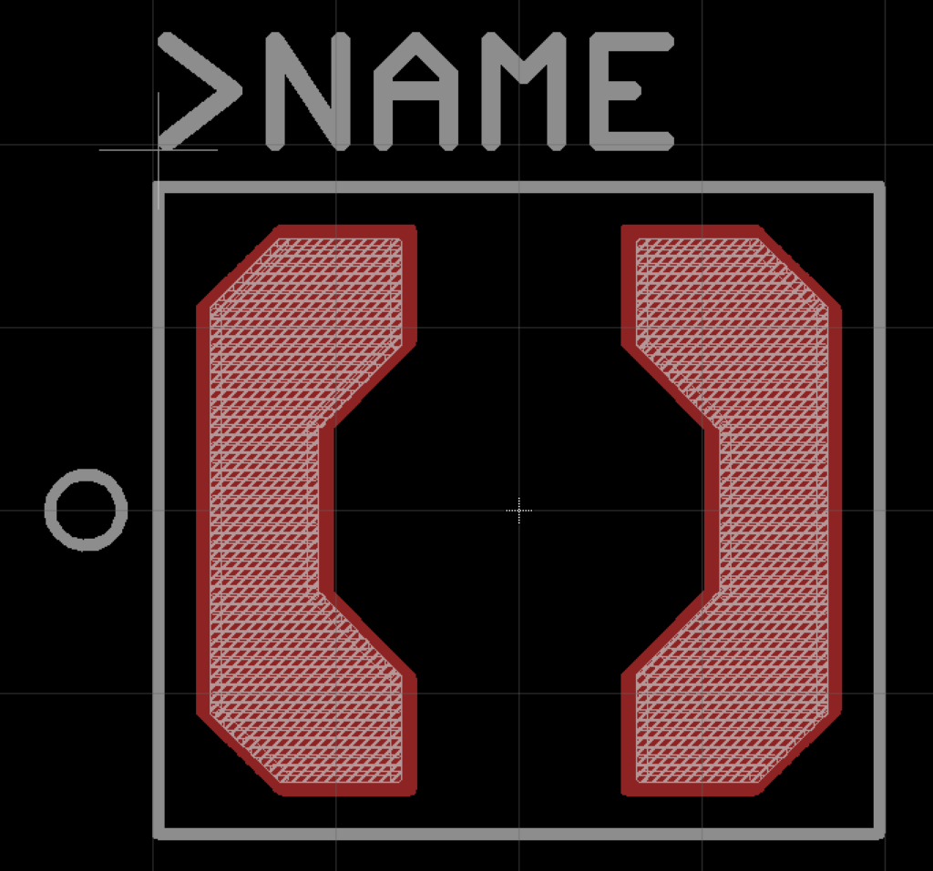
Anyways there is the part designed in Eagle. You can get it in my part library which is on github.
My “new” replacement switches for the record player arrived today.
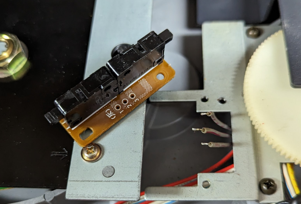
The new switches on the left with wiring harness and what is left of the broken switches on the right.
I desoldered the wiring from the new switch board and then removed the old switch board from the record player harness. Keeping in mind the orientation of the 3 wires.
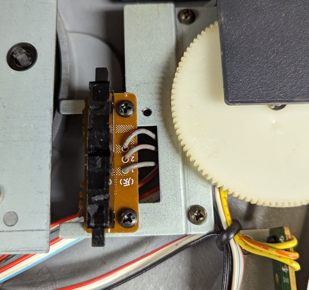
Then I soldered the wires into the new board and installed it.
Then I reassembled the record player, I did regrease the nylon gears with some “medium” weight silicon grease. Seems to work fine.
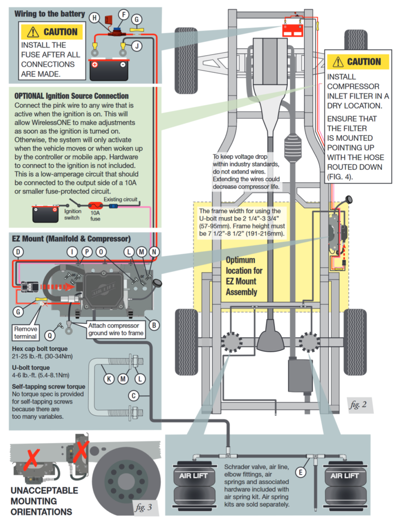
Part of rebuilding the suspension for the Jeep Wagoneer was adding air springs above the rear leaf springs to prevent it from sagging when loaded. Wagoneers suffer from “wag sag” when the leaf springs wear in and I wanted to prevent that and help keep the wagoneer level when loaded with fire wood or whatever I was hauling.
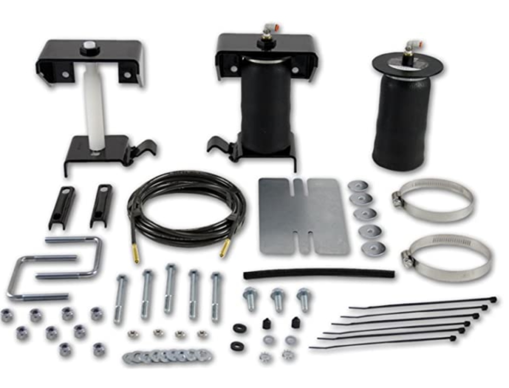
I choose the following AIR LIFT kits that seemed to work out ok for me.
AIR LIFT 59507
AIR LIFT 25980EZ
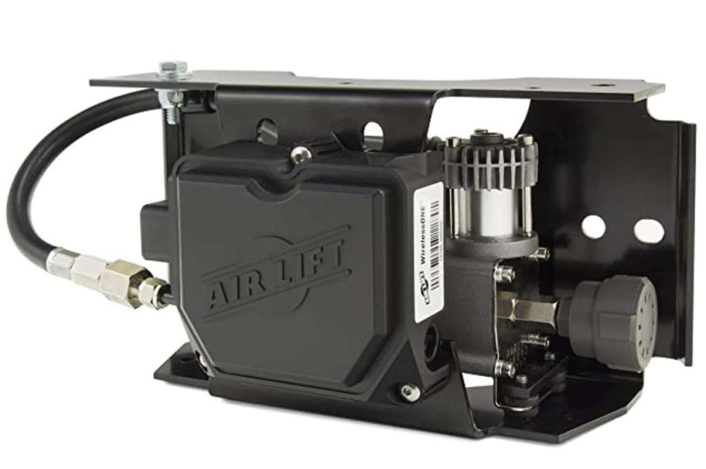
The AIR LIFT 59507 is the kit with all the brackets and air bags. AIR LIFT 25980EZ is a air compressor with controller that allows you to adjust how much pressure is in the air bags.
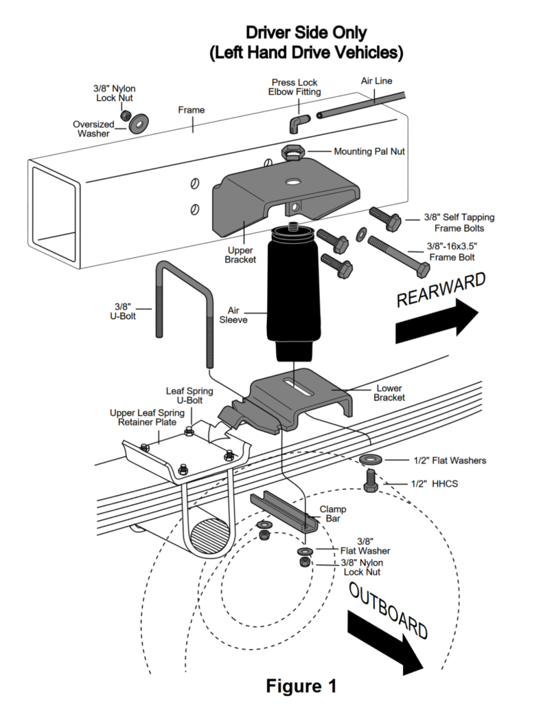
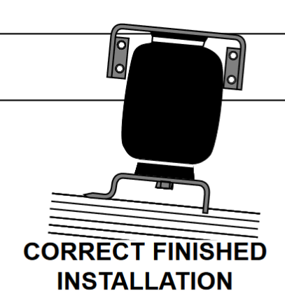
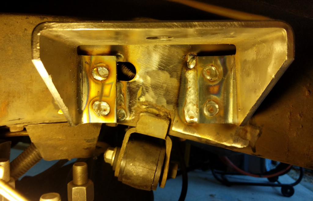
This is the typical install setup for the air bags. This didn’t work out for me though. The Lower Bracket is supposed to rest over the leaf spring retainer plate and bolt down with a u-bolt but I didn’t have clearance for the added u-bolt and the retainer plate was not shaped in a way that allowed the lower bracket to “hook” on to it.
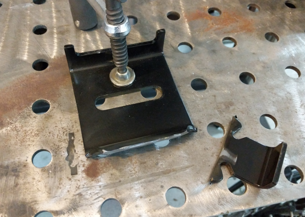
First thing I did was modify the lower bracket by modifying it to be mounted under the retainer plate. Cut off the tab that is supposed to slip over the retainer plate.
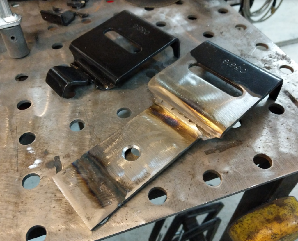
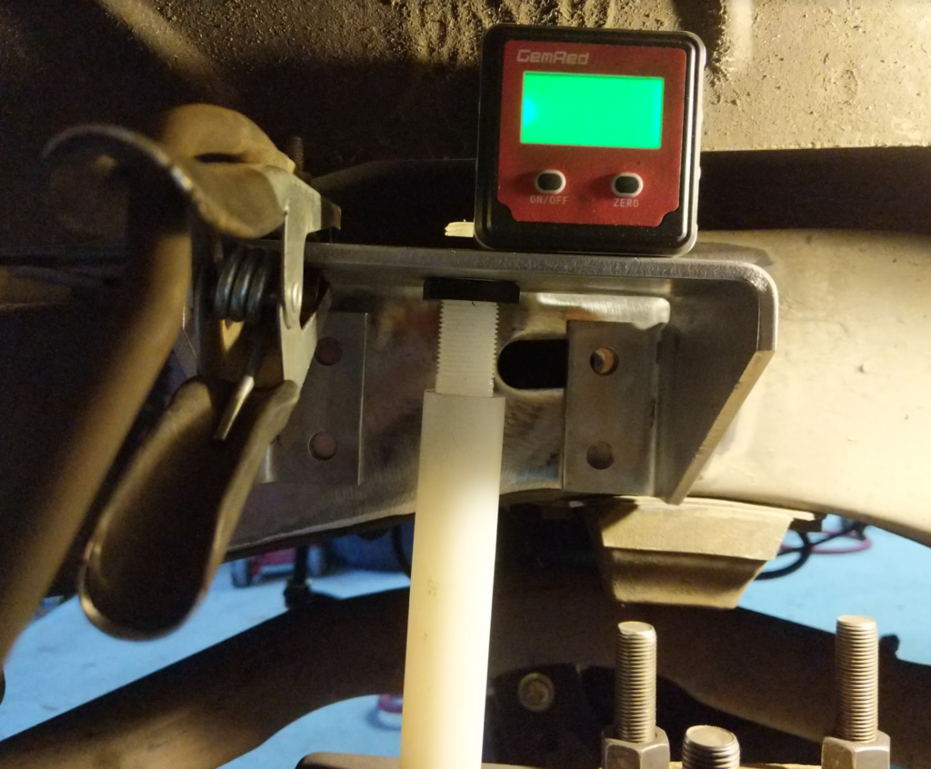
Then welded on a new tab with a hole drilled in it. This hole locates on the leaf spring pack bolt. Spray with some paint to keep the rust away. Bolt up the u-bolts and lower bracket for the air ride so we can mock up the upper bracket. The kit comes with a plastic rod with threads on it so you can set the height of the upper bracket. It has some adjustment and I set it close to the longest it could be since the wagoneer has lots of up travel in the rear suspension. Make sure the suspension leafs are compressed and at ride height when you are doing this. The upper bracket also needs to be parallel with the lower bracket.
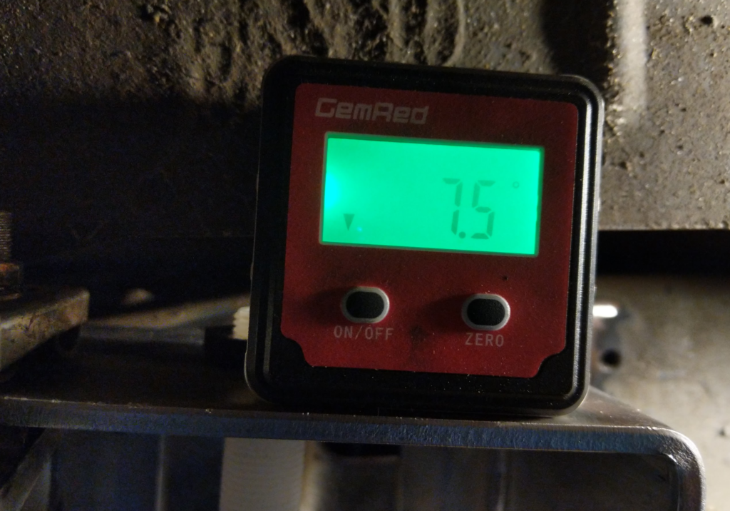
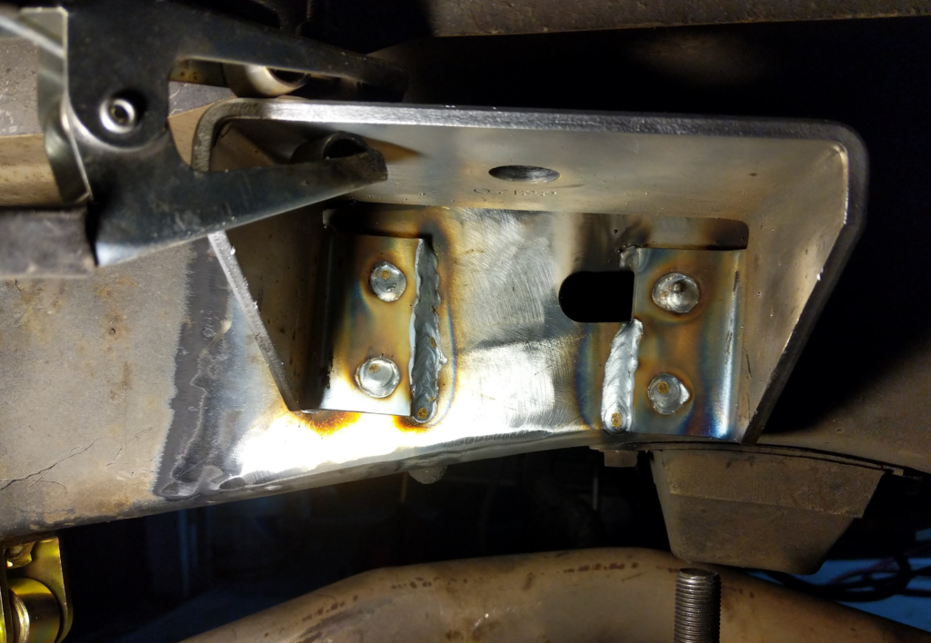
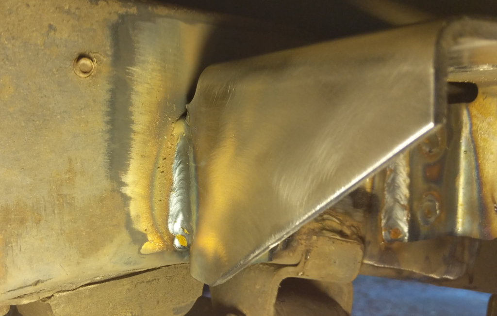
I decided to weld the brackets in when one of the bolt holes overlapped a hole in the frame. Wire brushed the paint off the upper bracket and the frame. Used a angle finder to make sure the upper bracket was parallel with the lower bracket and tacked and welded in the bracket. My upper bracket ended up being 7.5 degrees tilted downwards towards the front of the vehicle.
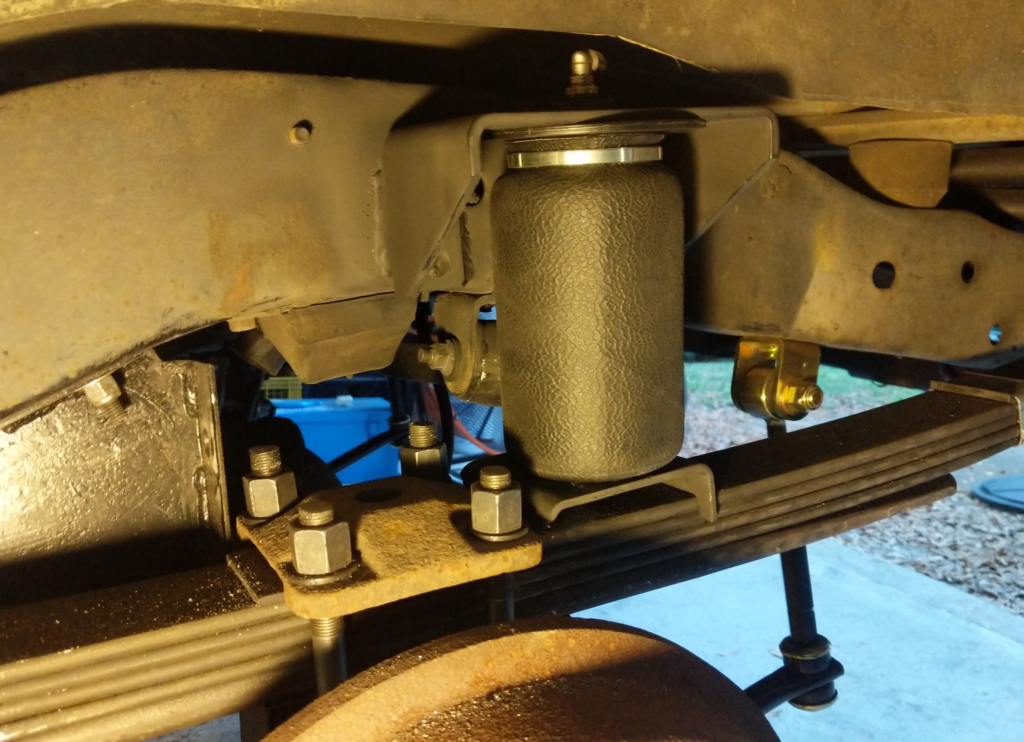
Coat it in paint and install the bag. Here you can see how the lower bracket wouldn’t mount onto the spring retainer plate in the normal way.
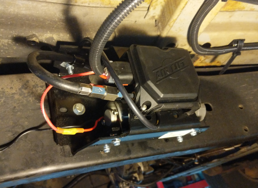
Then I mounted the AIR LIFT 25980EZ to the passenger side of the frame, about half way between the front and rear wheels.
Both air bags are plumbed up with a T to the output of the air controller on it. I put the inlet filter under the hood to keep it out of water.
I have been running this for over 4 years now and I really like how it turned out. I am planning on adding a T fitting and air line hookup so I can fill/refill tires with the system. Maybe this coming up spring?
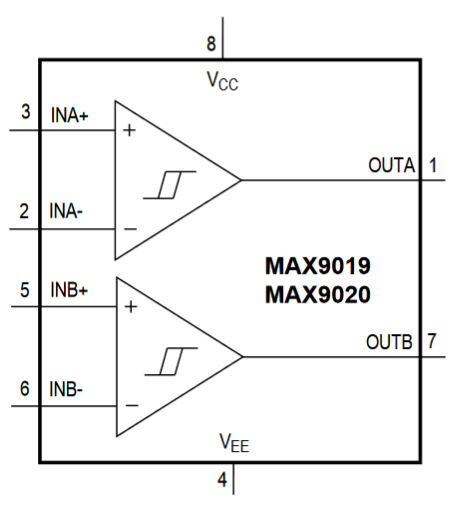
In trying to reduce the power consumption of the Cat Feeder Unreminder, I am going to explore using some really low power comparators to build the AC drive voltage I need to run the TN LCD segments.
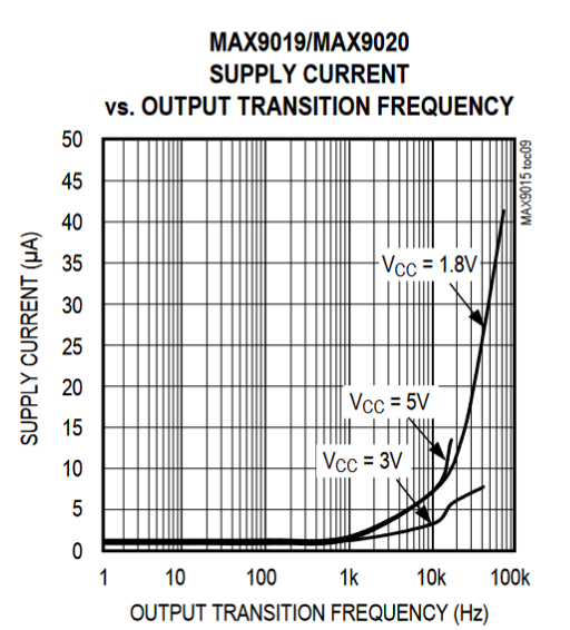
The MAX9019 is a dual package comparator fits the bill in the power requirements.
In the switching frequencies I am using (50-100Hz) it should only need a supply current of ~1uA.
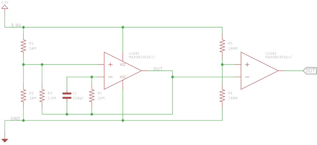
We setup the first comparator to generate a square wave and then the second comparator in the package as an inverter.
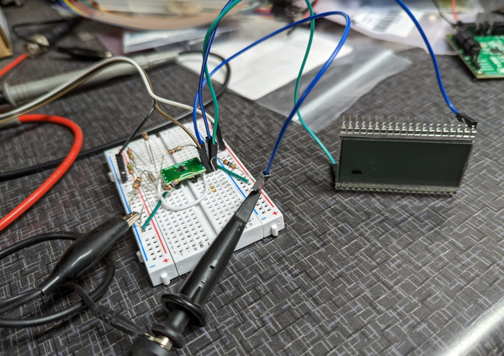
The design breadboarded up. It drives the screen!
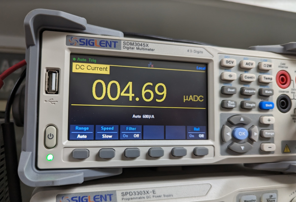
This is well under the resolution of my Siglent SDM3045X. Will have to wait to get the right equipment to measure the actual current the circuit is drawing.
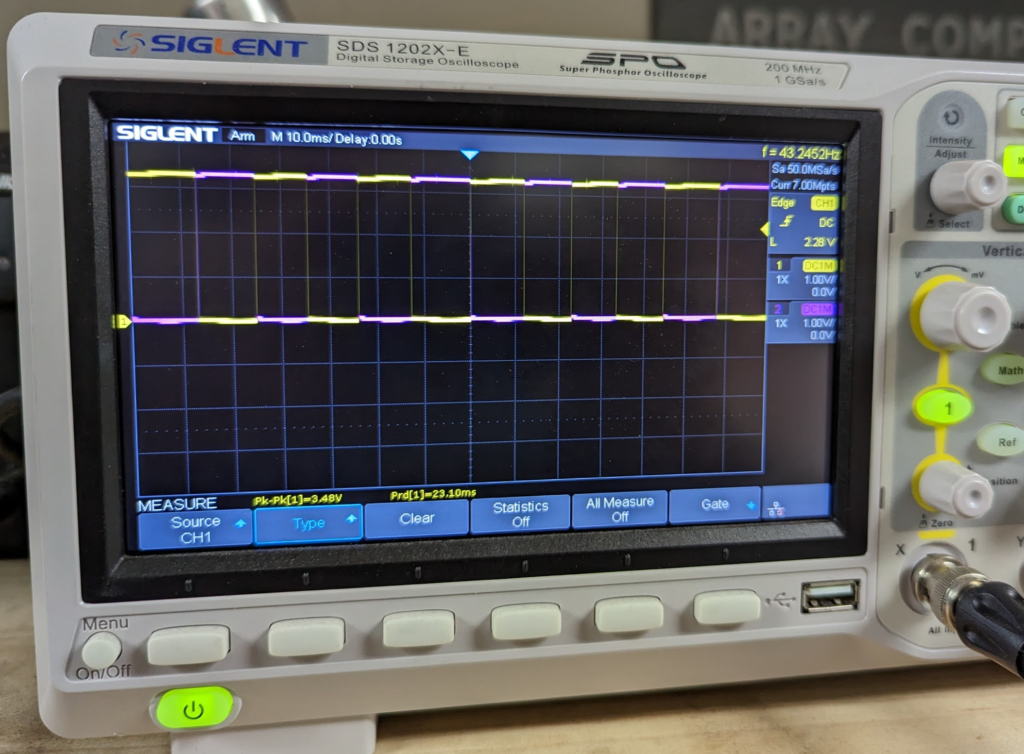
Here are the two output drive signals on the scope.
Next step to work on is the power retention system. The largest draw on the system right now is the leakage on the super capacitors! I found some super capacitors made by Eaton, HSL0814-3R8106-R, that specialize in having low leakage. Slightly higher ESR then some super capacitors but that isn’t that important for this project.
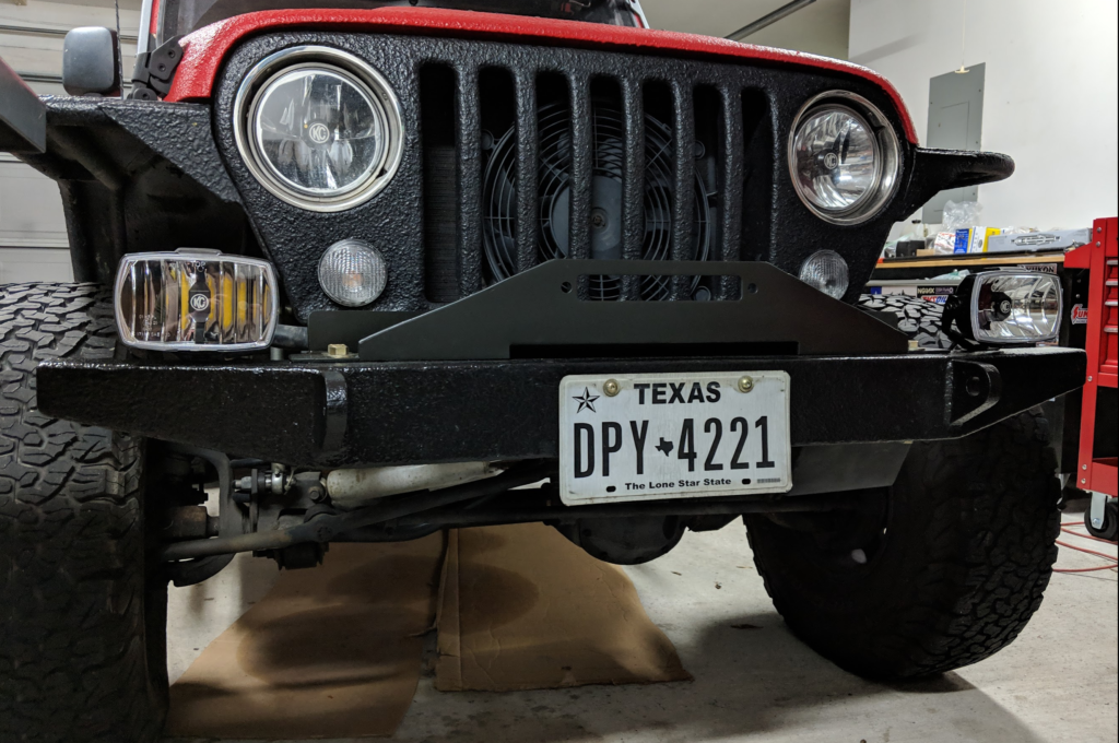
Time to get rid of the stock bumpers for the red jeep!
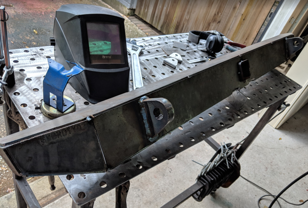
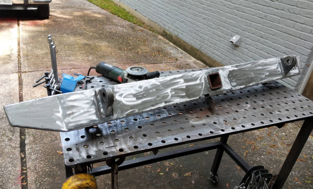
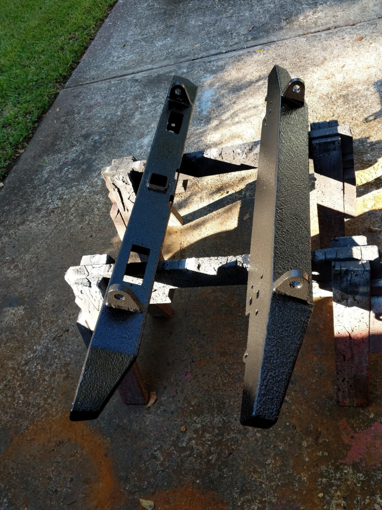
Every since I bought the Jeep I wanted offroad bumpers but never got around to it. I wanted some “simple” looking bumpers and I found a kit from JCR Offroad that would allow me to get some practice in with the welder! Front Bumper / Rear Bumper
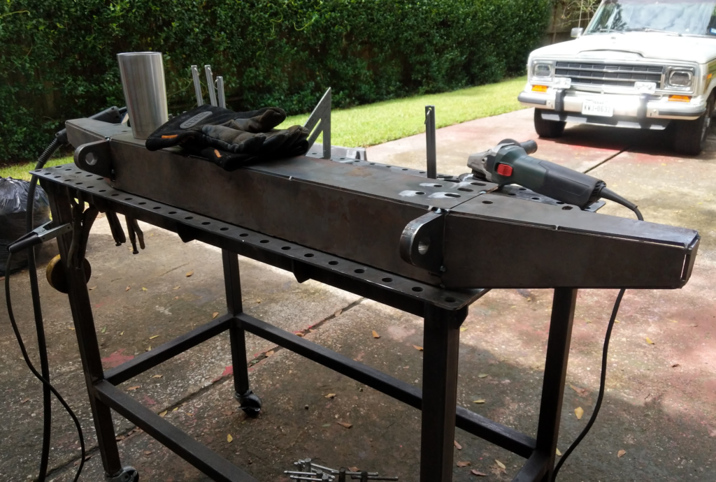
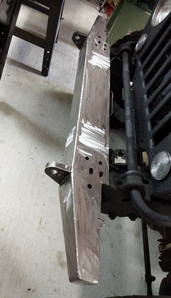
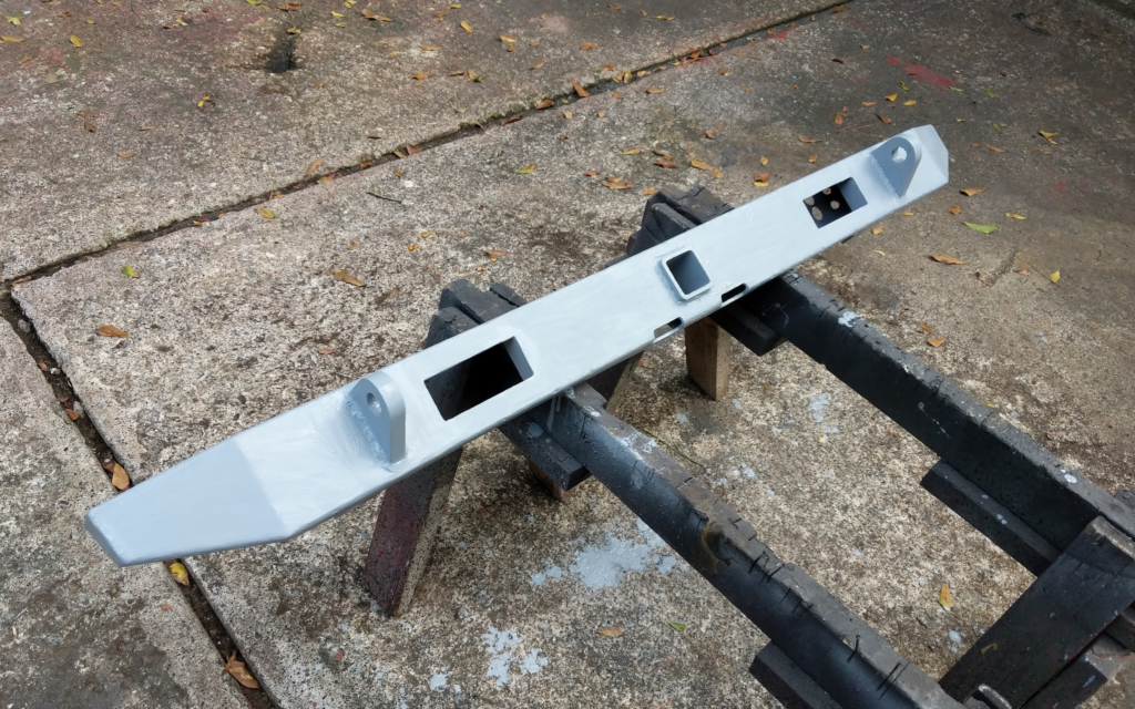
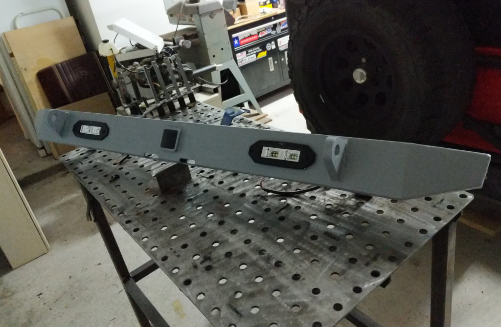
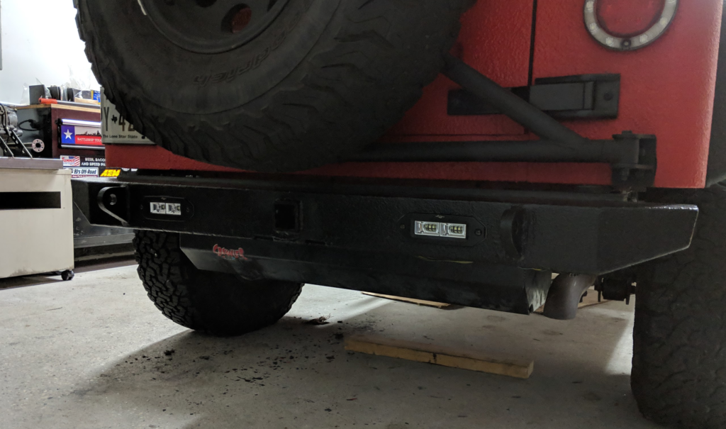
What I really like is that they are cut out of 3/16″ steel, have a low profile look, tow rope hookups, and the rear has an integrated 2″ receiver which is perfect for pulling small trailers around.
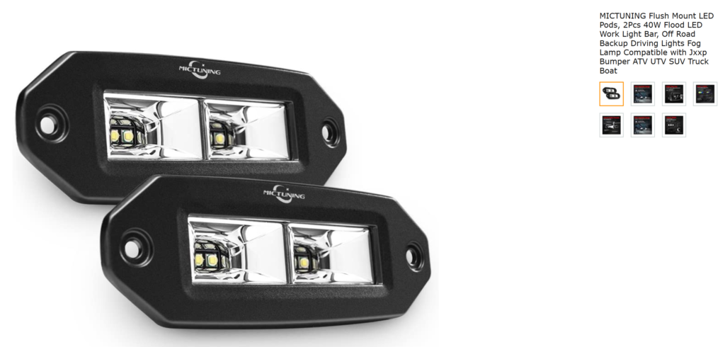
For the rear, I added cutouts for rear back-up lights. These are the ones I bought on Amazon.