
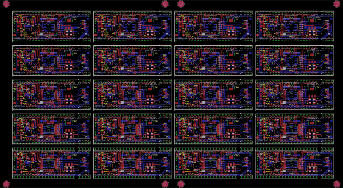
These are the test v-score panels. I also have a tabbed version of the panel in the fab for further testing.

These are the test v-score panels. I also have a tabbed version of the panel in the fab for further testing.
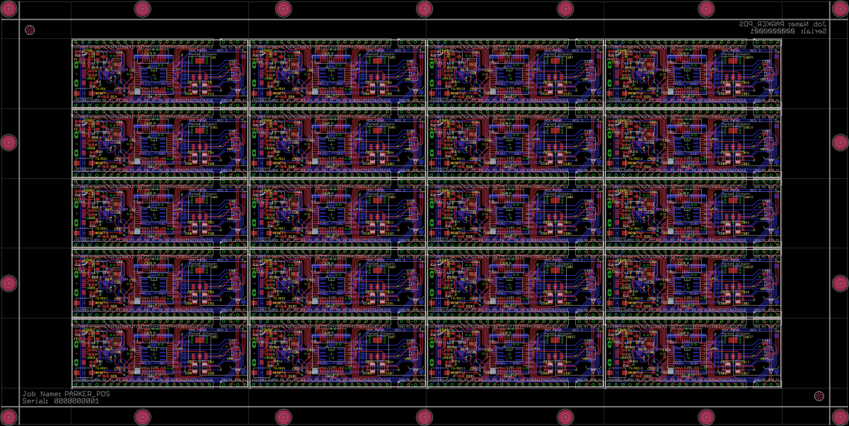
Finished placing the PDS into a 12″x6″ panel that produces 20 individual boards.
Just finished the documentation for the PDS REV 2. You can find the complete documentation on my github repository. Working on Panelizing the board for assembly and the Kickstarter video.
The Prop Dev Stick gets a quick review and demo by the Tymkrs!
Big thanks to them for helping me get the word out about the board.
Follow the Tymrks on twitter: @tymkrs
Uploaded a video explaining a bit more about the functionality of the AT2 and the waveforms of the op-amps.
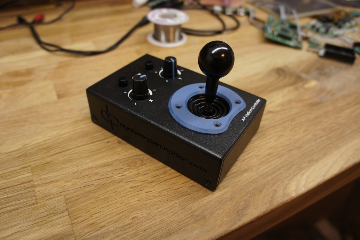
This is the first consumer product I ever designed for Dynamic Perception. The AT2 Motion Controller is a dual brushed DC motor controller that offers control with a joystick or a kind of cruse control with the knobs. In Joystick mode, the knobs act as adjustable dampening for the motors. The dampening is adjustable from 0 seconds to 5 seconds. In knob mode the knobs set the speed of the motors. Modes can be swapped individually for each channel (1 in Joystick and 1 in knob) is possible with the push buttons.
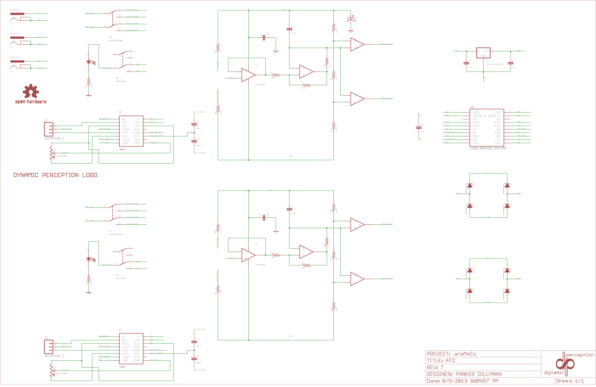
Above is the full schematic. You can download it and the design files at Dynamic Perception’s github. Everything for the board design is open sourced.
The AT2 can accept a voltage power source from 7V to 16V and power two 1.2A 12V motors. Motor controller is a standard L298 motor driver which should be recognized by most hobbyist.
There are no microcontrollers in the AT2. Each channel uses 4 op-amps to create a pair of square waves to drive the L298 via PWM.
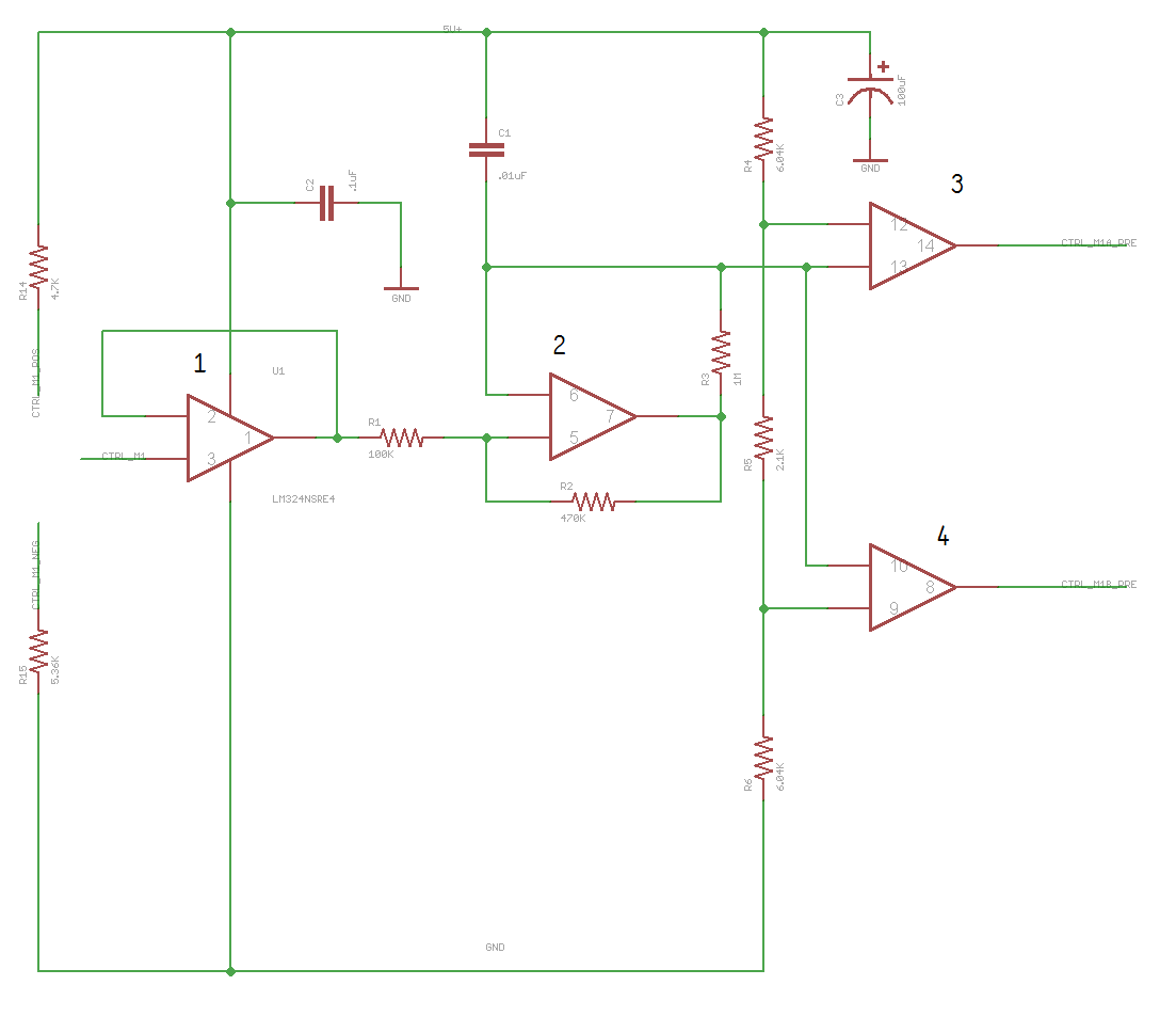
The first op-amp is just creates a high impedance input to the generator. It is set up as a voltage follower to pass the voltage that the knobs or joystick output. The knobs and joystick do this by just creating a voltage divider. Second op-amp creates an oscillating triangle wave at around 75Hz. The voltage from the first op-amp sets the voltage offset of this triangle wave. The third and forth op-amps are voltage comparators. One is set to trigger at above a certain voltage and the other is set to trigger below a certain voltage. These voltages are set by the voltage dividers. The output of the voltage comparators are the PWM wave that the L298 sees. I have seen a couple motor controllers that operate this way.
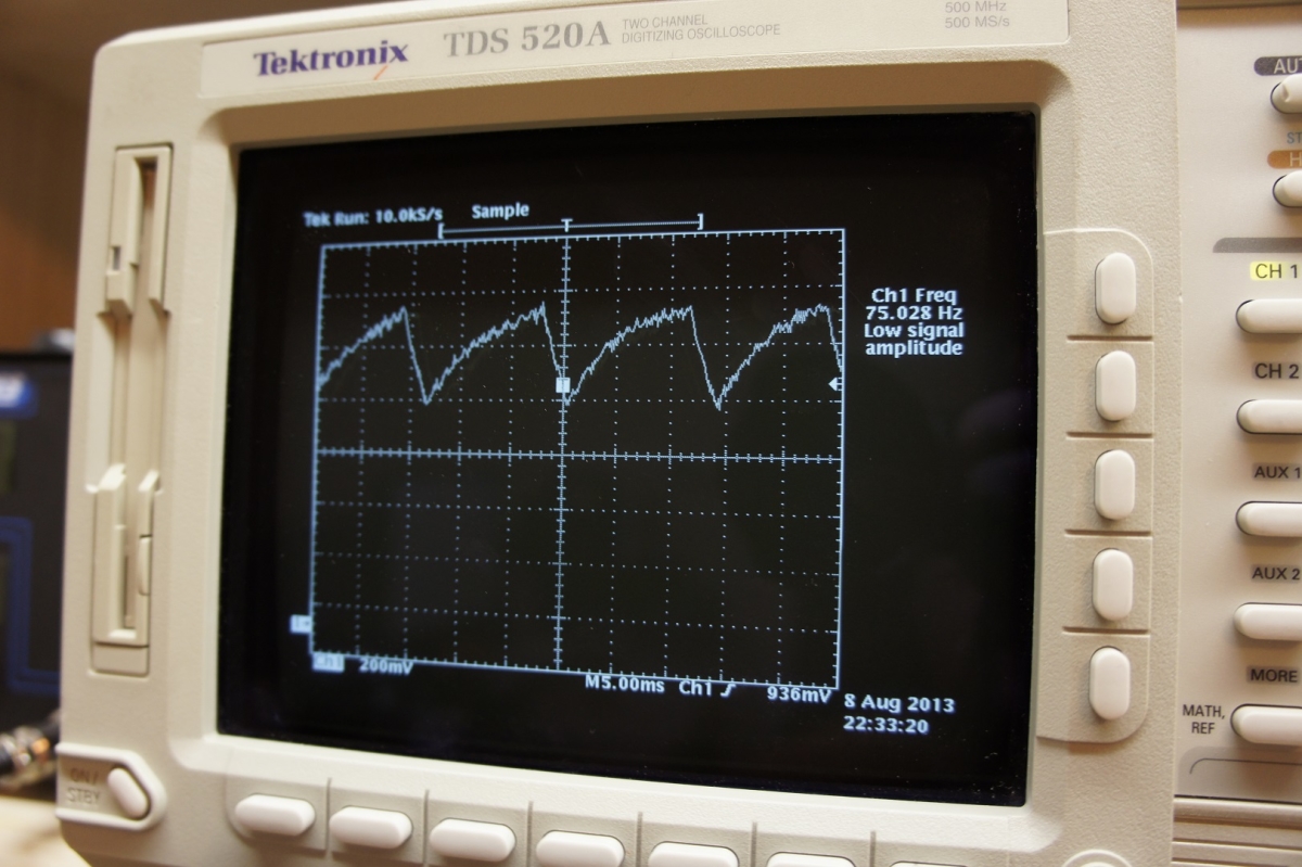
This is what the triangle wave looks like.
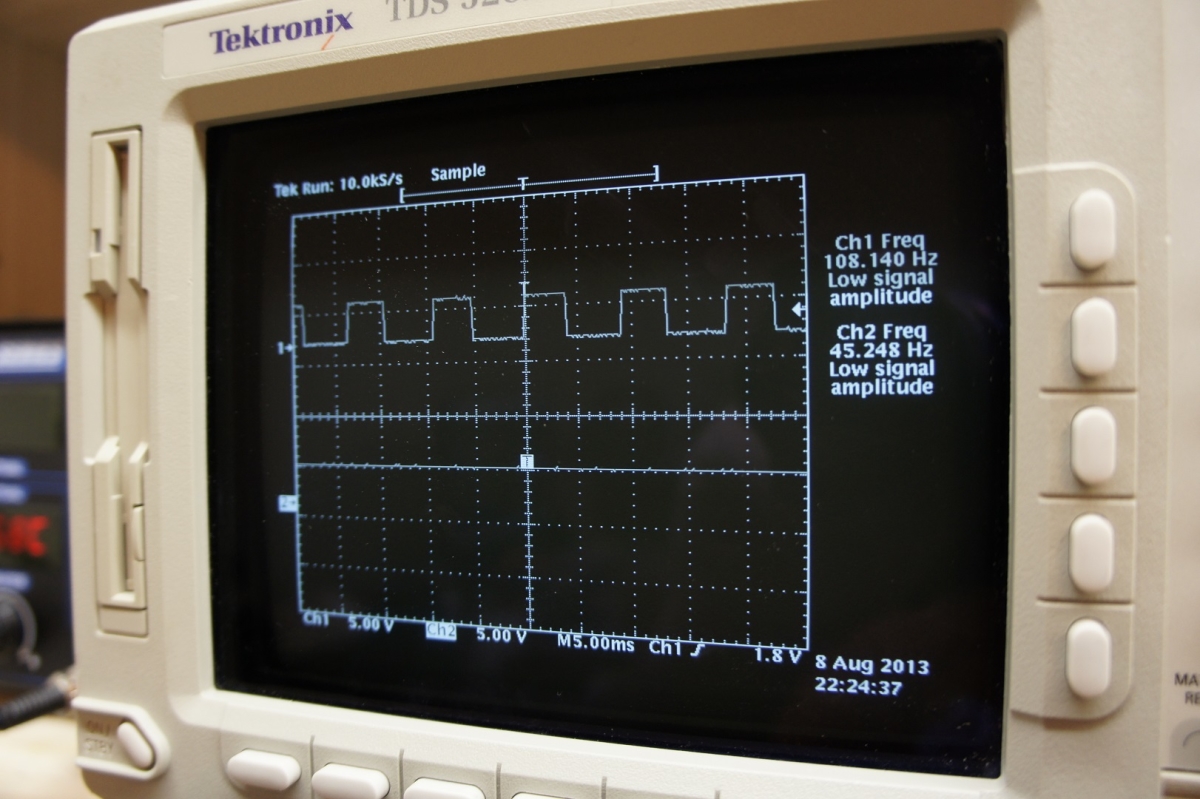
When the triangle wave is activating the top end voltage comparator. This is with a high voltage input to the first op-amp.
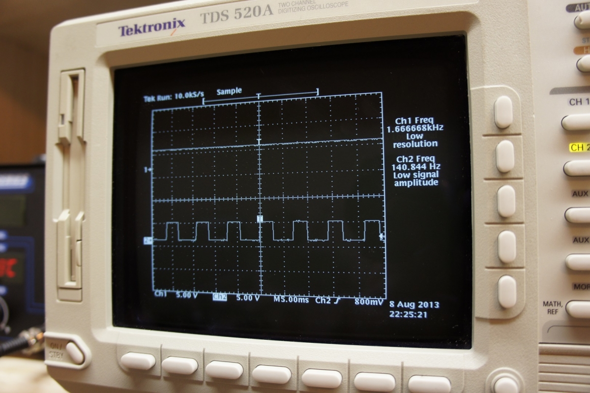
When the triangle wave is activating the bottom end voltage comparator. This is with a low voltage input to the first op-amp.
It took 8 revisions to get the functionality and design of the controller correct.
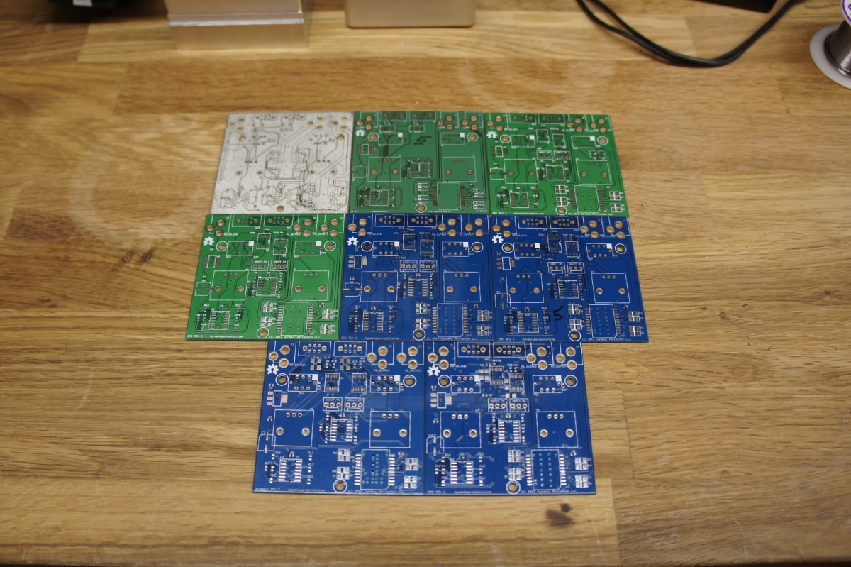
The first prototypes are in the top left with the final revision being the bottom right. I will never order a board without silkscreen again.

This is the progression of the case design with the oldest prototype on the right side.
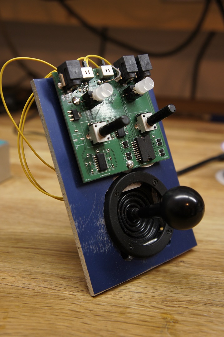
First hacked together prototype. I just took a piece of scrap aluminum to make the “chassis”.
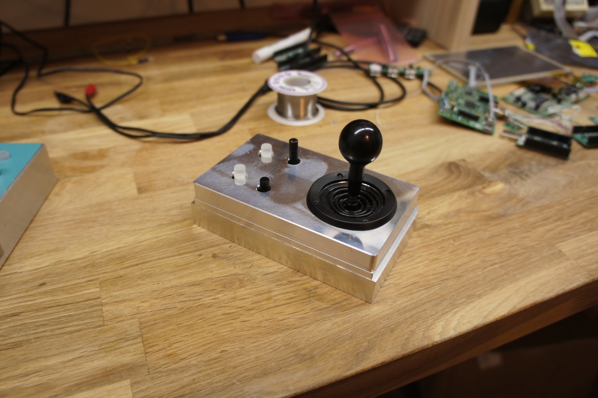
Second all aluminum case prototype. This proved to be too heavy and costly to machine.
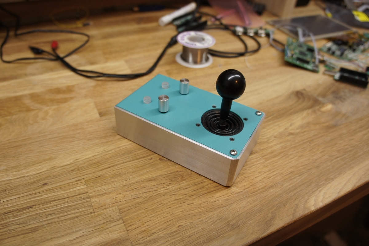
Third prototype with a hybrid case. My personal favorite. It has an aluminum bottom and a plastic top. The weight was perfect but it still was still too costly to manufacture.

Forth case with the curved plastic on top. This decorative piece of plastic prevented easy access to the motor and power connectors to it was removed.
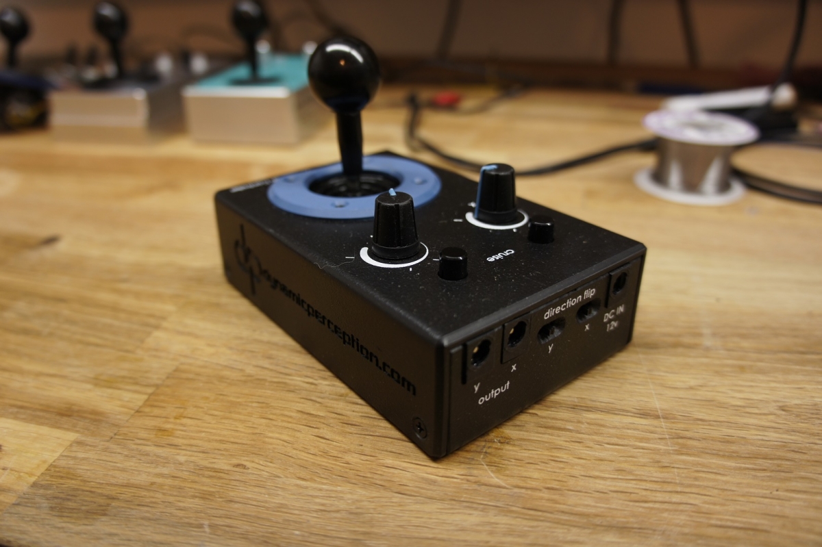
Final design with silkscreen. The plastic is a really tough ABS which resists cracking. The texture of the plastic is also nice to the touch. Rubber knobs cap the potentiometers.

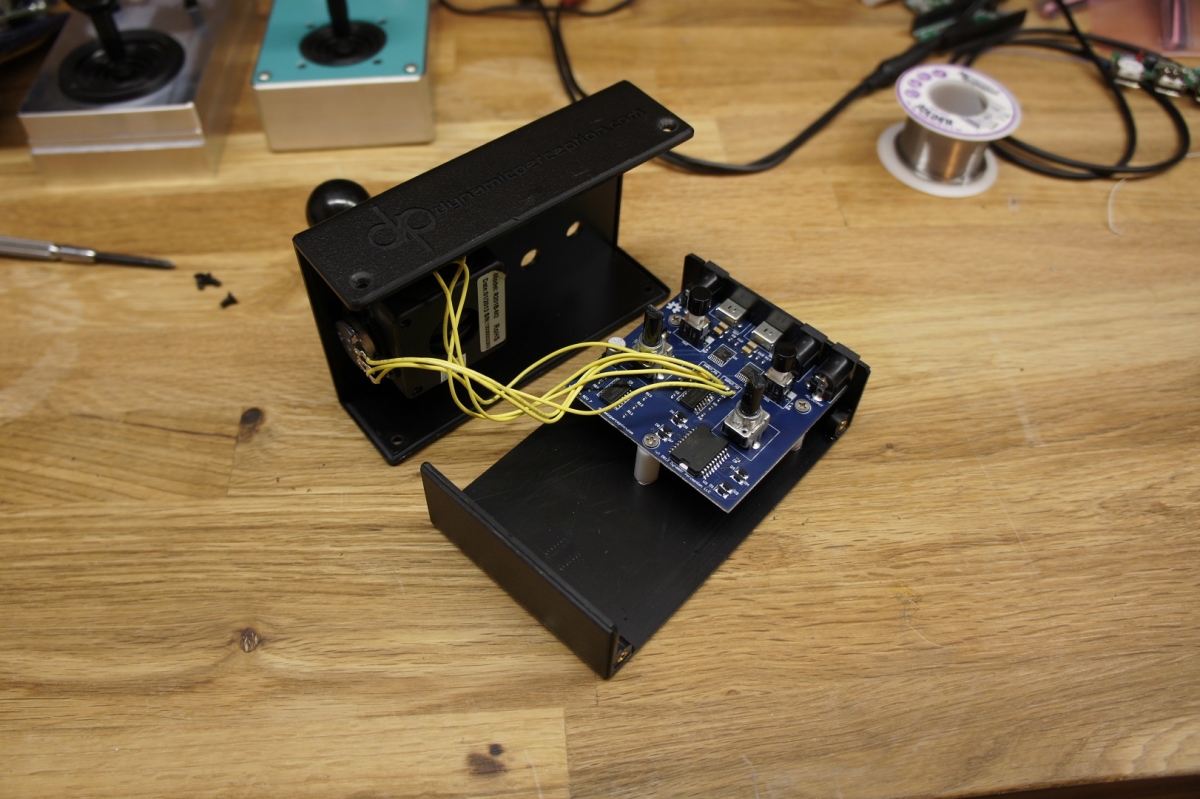
Some inside action on how it is all wired together.
You can buy the AT2 Motion Controller from Dynamic Perception.
I have the first 5 Prop Dev Sticks boxed up for testers. I will be dropping them off at the post office tomorrow. Hopefully no hardware bugs pop up!
Also I am looking into adding more daily blogs posts. Content like app-notes, engineering design thoughts, and interesting parts.
I updated the PDS repository with information on how to configure the FT230X EEPROM and the Propeller Tool IDE.
Template for FT230X EEPROM
You will need to download FT-Prog from FTDI. The FT230X needs to be flashed with this template for the Propeller Development Stick to function correctly.
Also the Propeller Tool needs a tweak to its options to make it use the RTS signal to reset the Propeller instead of the DTR signal (which the FT230X does not have). Do this by opening Propeller Tool and clicking Edit. At the bottom there is “Preferences”. Under the tab “Operation” there will be Propeller Reset Signal. Change it from “DTR” to “DTR & RTS”. Press accept to save the settings. Propeller GCC using SimpleIDE also allows you to change the reset signal in the general tab of properties.
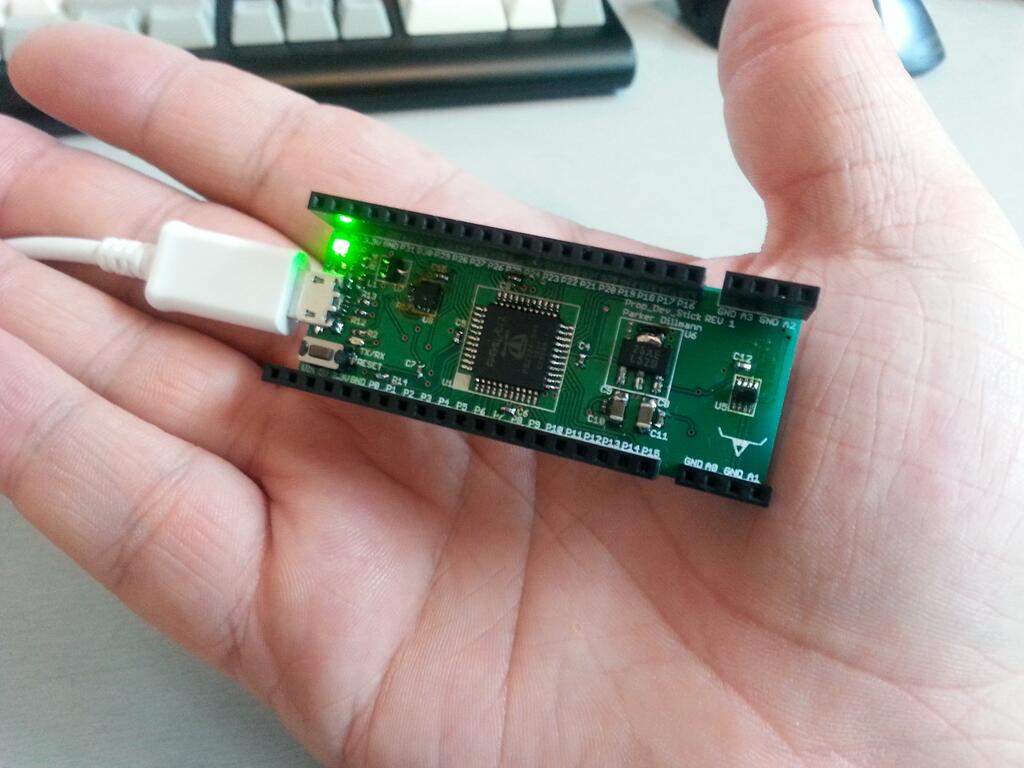
The Propeller Development Stick (PDS or Prop Dev Stick for short) is a simple development board for the Parallax Propeller Microcontroller. I already had an older design but I wanted to expand the usefulness of the platform. The Redux version throws out the old version completely and starts over from scratch.
The new PDS features a ADC and a micro SD card slot for storage. Also the speed of the Propeller gets a 16MHz speed bump (from 80MHz to 96Mhz) with the addition of a 6Mhz crystal. Form factor is improved by slimming down the design which enables it to fit on a breadboard. The old USB male plug is gone and it now uses a standard micro USB. This way the user can embedded the device and still program or pull data off of it.
It fully complies with the USB standard. The device uses the FT230X USB to Serial chip and waits to turn on the power buss in till the PC gives the device permission to pull power. This is done by a p-channel mosfet. To switch from USB power to external power (like a battery) a power mux is used. The mux has built in current limiting which is set to 500mA.
Last night I soldered the new REV 1 board. Everything is working correctly and the footprints/silkscreen are also correct. Will be working on the page documenting the progress of the PDS. Will also upload the design files.
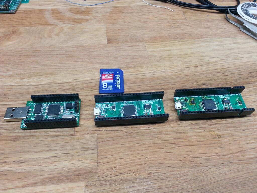
Progression from the first PDS on the left to the newest one on the right. Slightly longer but slightly thinner now. Changed the USB port to a micro usb port. Added an ADC and mirco SD card slot.
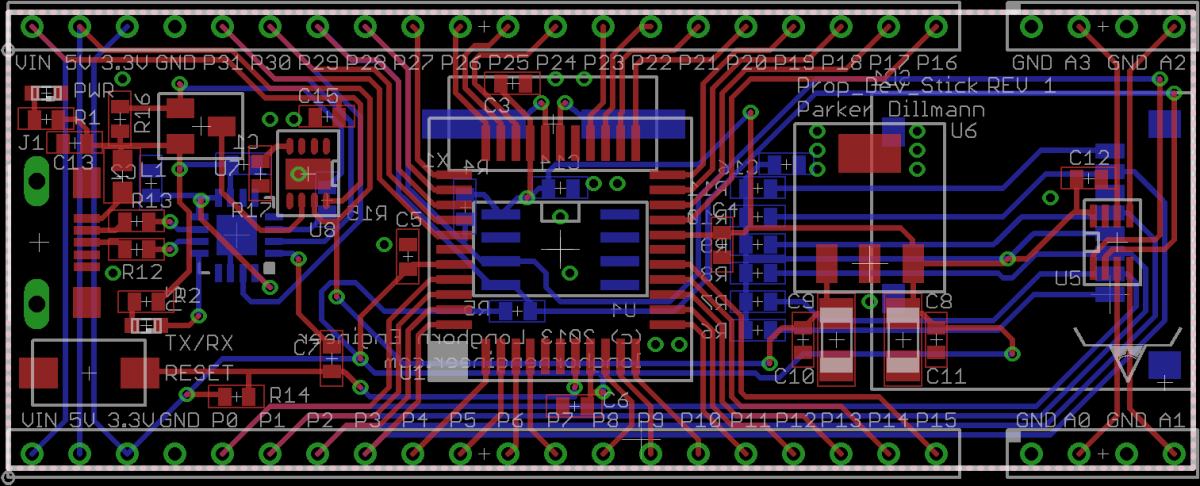
Layout of the PCB.
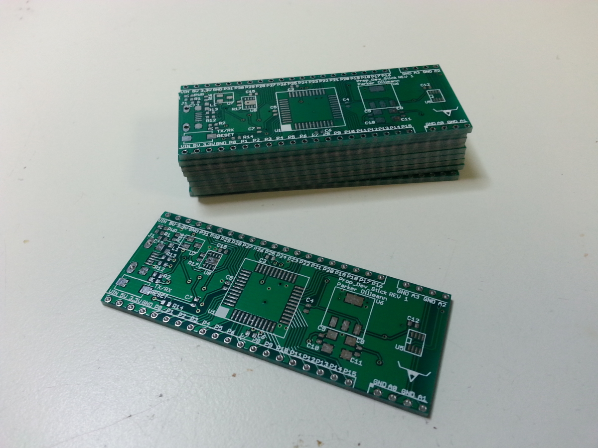
Just arrived from China. This revision has some minor footprint fixes and the correct pinout for the SD card slot.
Will put the design files up this weekend after I verify that the SD card slot works.
Going to ship a few for testing. Interested? Comment below!