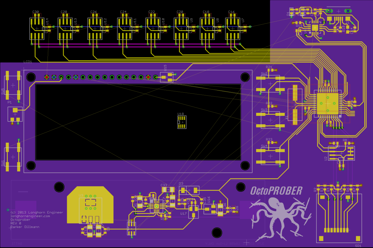
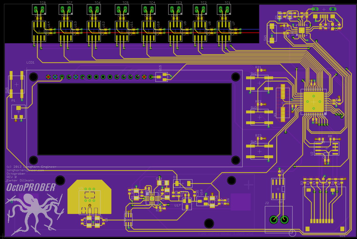
Repository contains test code and all the files so far. Board grew .15″ in height to make space for the headers.

Repository contains test code and all the files so far. Board grew .15″ in height to make space for the headers.
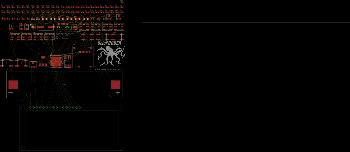
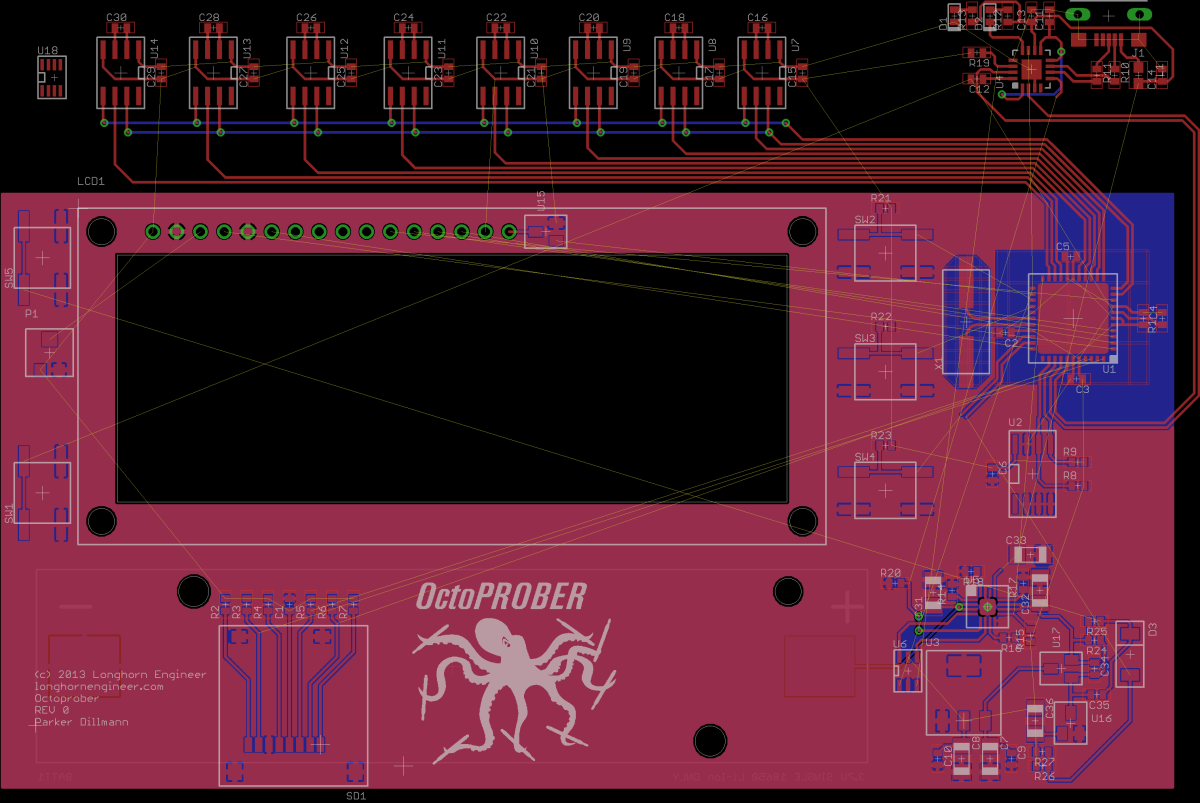
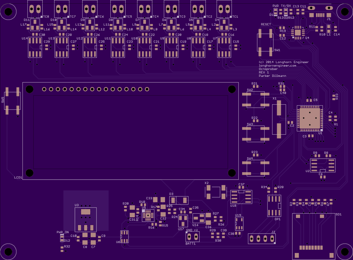
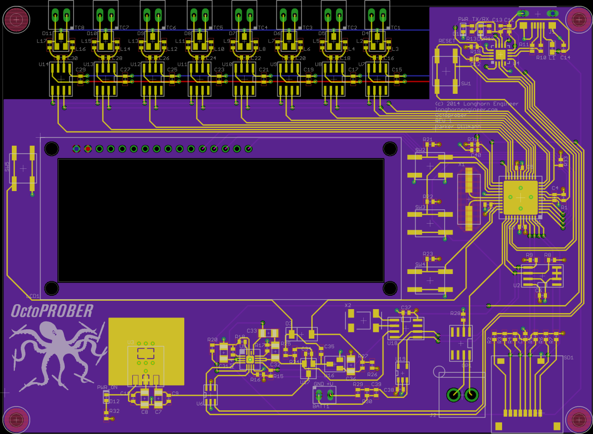
Finished routing the hardware fixes that I found while testing the OctoPROBER. Was able to add another optocoupled output for auxiliary devices.
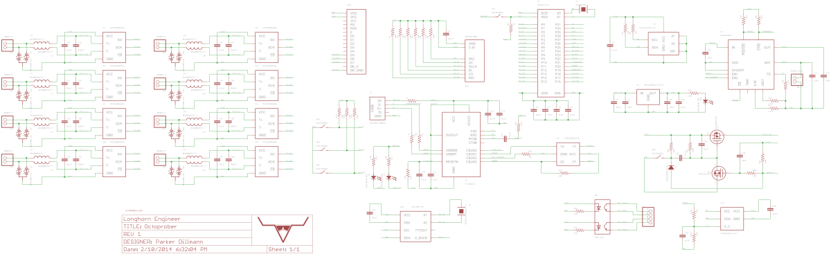
Just need to clean up the schematic for the final release.
I am using the DS1340Z-33 RTC for time keeping on the OctoPROBER. Interfaces with i2c. It has a built in trickle charger which I disabled as the RTC pulls power off the main lithium battery when the device is turned off. Last thing to test are the MAX31855K thermocouple chips….kinda the entire reason I designed this board hehe.
Finished programming the ADC which is a MCP3021. It is a 10bit i2c compatible ADC with one channel. A limited ADC but perfect for measuring battery voltages.
Operation is very simple. Just request a word from the device using 10011011 as the device ID and it will spit out the analog value. I had some issues with the i2c driver I used though.
The ADC is supposed to return the 10bit value like so 0000XXXXXXXXXX00. I was receiving XXXXXX000000XXXX. The upper and lower bytes where transposed. Fixed by swapping them around.
*With hardware fixes
I was having an issue with the FT230X being active while the 3.3V rails being turned off. The FT230X would backfeed voltage down the TXRX lines into the propeller which would power the 3.3V rail to ~2.7V causing the soft power switch circuit to turn on. I fixed this by running the RESET pin of the FT230X to the propeller and pulling it up to the switched 3.3V rail. The propeller can control whether the FT230X is in suspend mode or is active. Pulling RESET low will HI-Z the TXRX pins and allowing the propeller to turn off the soft power circuit completely without voltage backfeed.
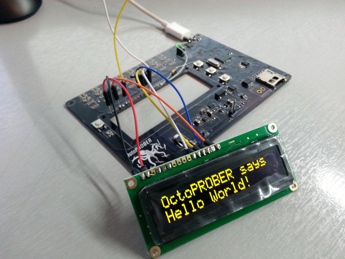
Changed the 16×2 char display from running in 4-bit parallel mode to serial com. This saves 2 I/O lines and is much faster then the 4-bit mode.
Since the main way of charging the OctoPROBER is over USB I needed a way to disable the auto reset. Don’t want the device to reset when its taking samples and low battery warning pops up! This is cause when a computer connects to the FT230X it sends a reset signal to the FT230X which is connected to the reset line on the propeller. Disconnected that and routed the FT230X signal to a free I/O line. This way the prop can control whether or not to reset upon connecting to a computer.
Couple more hardware systems to test then REV 1 boards will be ordered!
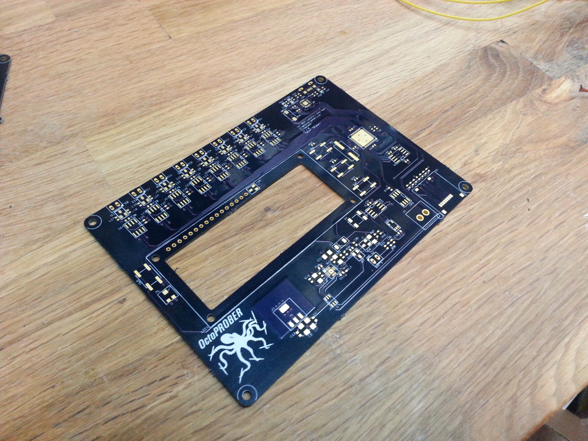
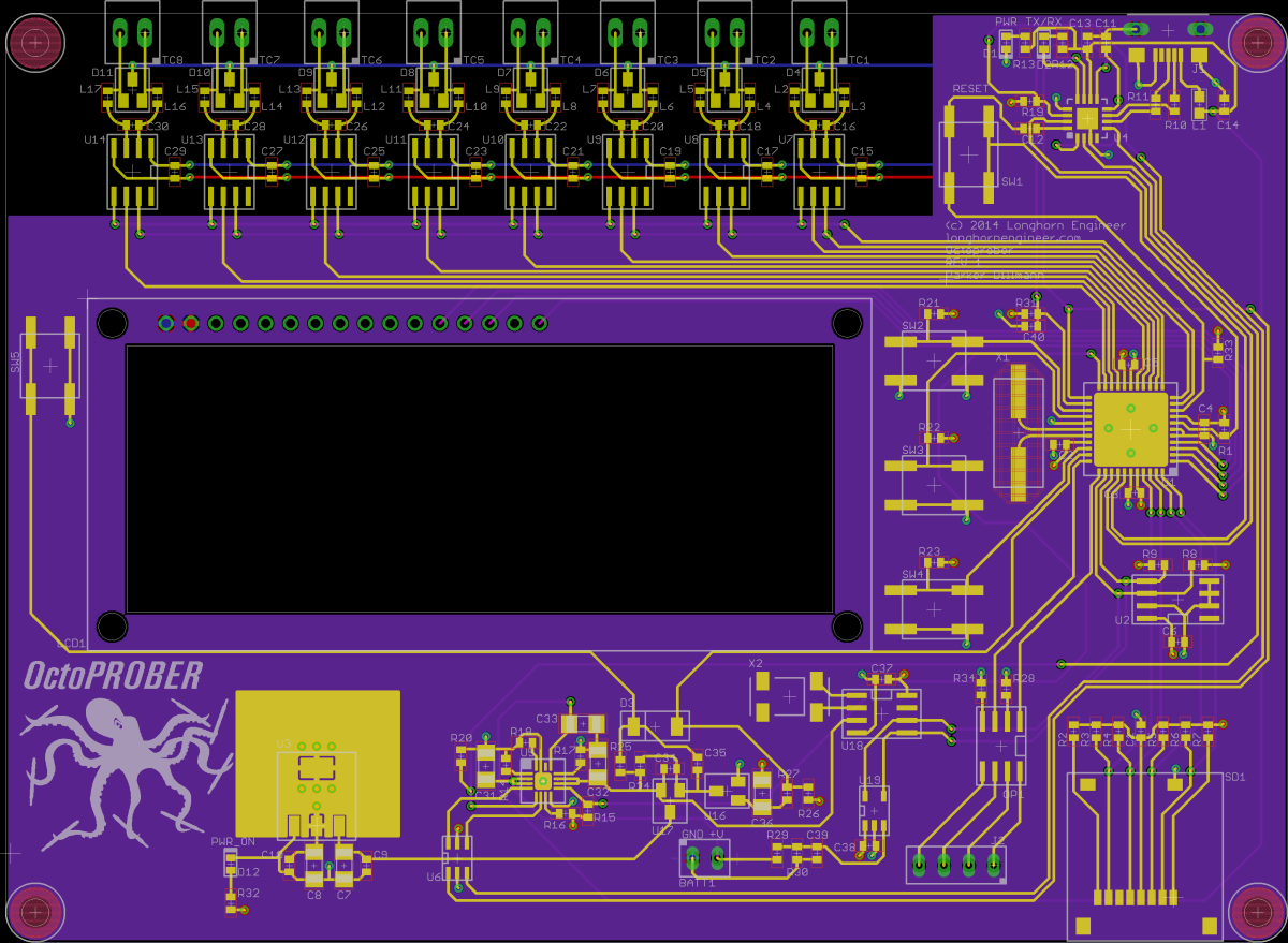
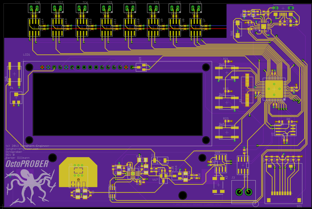
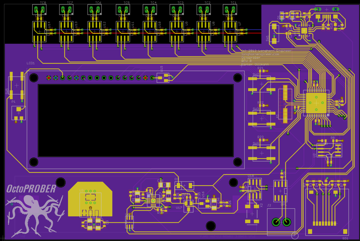
Three boards arrived from OSH Park today. First 4-Layer board I have ordered from them. Quality is pretty good. Silkscreen is a bit weak but that is probably due to me running the weight of the text to thin.
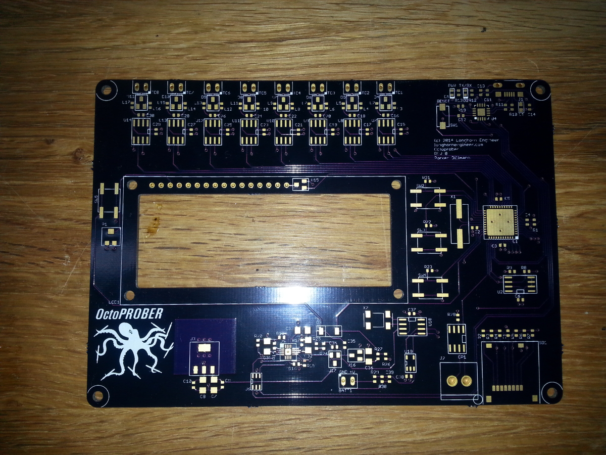
Internal two layers are GND and 3.3V. Outside two layers are signals.

Close up of the kickass OctoPROBER logo.
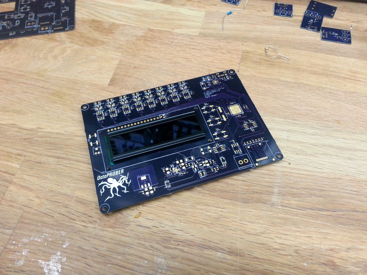
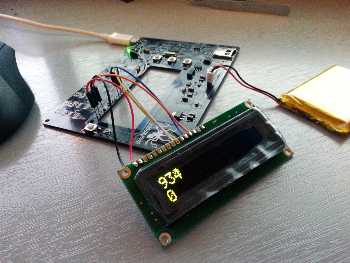
Character display mounts on the back of the PCB. This way the PCB can be mounted to the front of the case without silly long button caps on the tact switches.
The Pinheck Pinball System uses a PIC32MX795F512L-80I/PT mcu. It is a 32bit mcu running at 80MHz with 512KB of program space. Plenty fast enough for pinball. The only reasonable package it comes in however is TQ-100 package which has a pitch width of 0.5mm. This pushes the limit of the vision system of the DP2600-2 but I managed to get the system dialed in to make the placement.
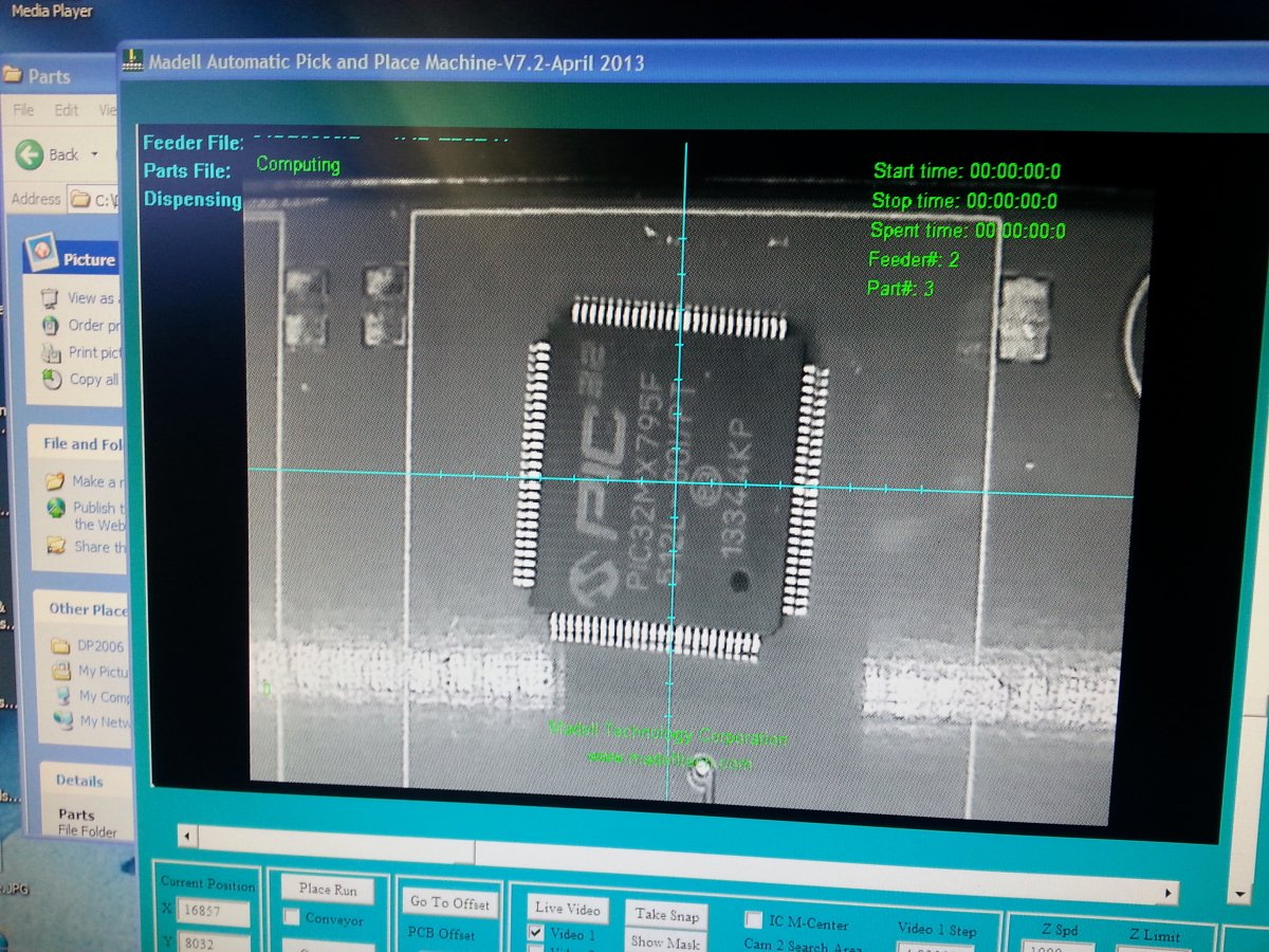
The PIC32MX795F512L-80I/PT is a tray part so the machine does not pick the part up from a feeder. Instead you line up all the chips in a row and the machine knows where to look for it. Uses the vision system to find and locate the part.

After picking up the chip the machine takes it over to the “Uplook” camera. Here is can make sure the part is oriented correctly and lined up.
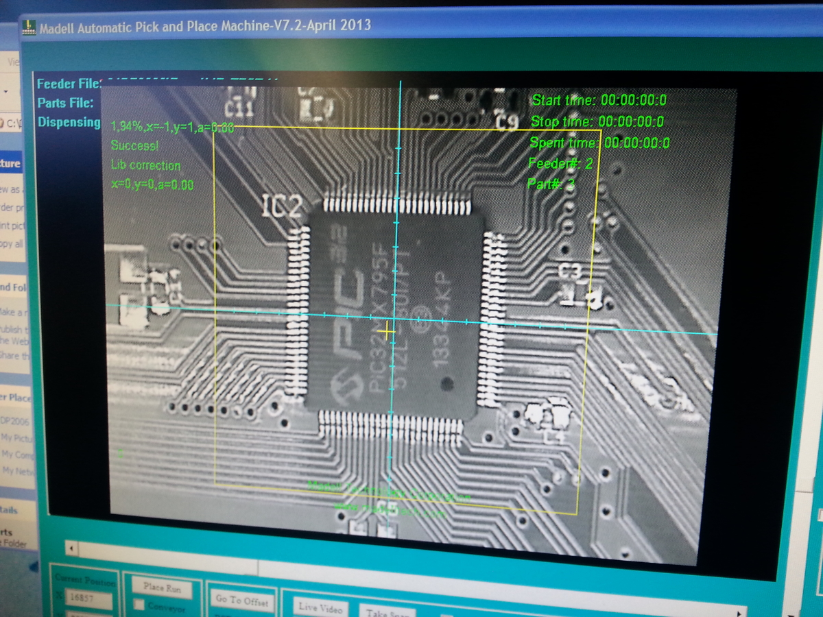
The machine then moves on over to the part location on the PCB and places the part. In the image you can see the dark areas between the shiny leads of the PIC32. The dark areas are the solder mask showing through which means the part was placed correctly and straight.
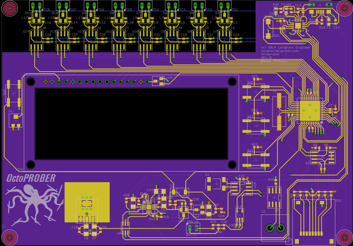
Finished REV 0 of OctoPROBER last night. I added a MCP3021 which is a I2C 10bit ADC with one analog channel. It will be used to monitor the battery voltage and indicate when the lithium battery is close to being dead.
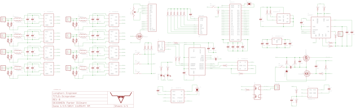
Schematic is a bit of a mess but I will be cleaning it up.
Files are on GitHub. Will start programming the hardware test software this weekend for the propeller.
An update on the OctoPROBER layout. I added a Real Time Clock (RTC part # DS1340Z-33+) to the I2C buss. Temperature recordings can be logged with an accurate time stamp.
To keep the time when the unit is off it pulls power directly from the lithium battery. When the OctoPROBER is powered on it pulls power from the 3.3V power rail.
Speaking of the battery the OctoPROBER’s main power source is a 18650 lithium cell. Power draw is around 200mA so a 2600mA battery will last around 13 hours. The RTC in standby mode pulls 125uA max which gives it a max standby time of 866 days. That should be plenty for most use cases.
Late Edit.//
Fixed some more traces. Just need to work on cleaning up the silkscreen then it is off to the fab house!
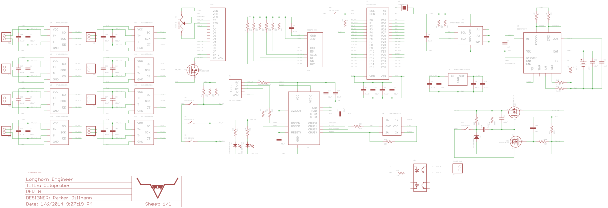
This has been an idea I have been kicking around for awhile. The OctoPROBER is a 8 channel, K-type thermocouple temperature logger. It has a micro SD card slot for logging data remotely. The USB connection can send log data directly to the PC.
Power is supplied via internal lithium 18650 3.7V cell and is charged over USB. The BQ24075RGTT is used to manage the charging of the lithium battery by using the outputs of the FT230X USB chip. I will cover this in more detail when I can verify my idea will work.
To prevent corruption of the SD card a soft power circuit is employed. A single optocoupled output is given to allow control of an external circuit.