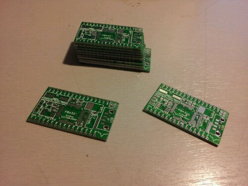
I only have 2 out of the 10 left from the initial run of V1.1. The first batch for those that have already ordered will be shipping this Friday. PDS V1.2 already has some design changes that will increase the boards functionality and usefulness even more without adding to the cost of the final product.
If you want to grab a the PDS V1.1 for testing send me an email. Cost is $25+$3 shipping which is the at cost price to make the PDS in low quantities.
V1.2 will hopefully be the full production version and will retail at $40ish.
Here is some analysis of the power lines and noise on the board. These measurements are taken with no load on the I/O besides what is built in on the board. Pins 29 and 28 run the EEPROM in I2C mode on boot to load the program into the Propeller.
With the Propeller doing nothing the board takes 7mA on the 5V line. Flipping all the ports as fast as the Propeller can do it at takes 20mA at 5V. Turning on all the cogs (8) and flipping the pins takes 94mA which is almost 1/5th the power budget of the USB spec (5V 500mA). During these measurements the board was powered with a dedicated lab power supply.
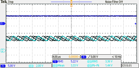
Here is the worst case noise analysis of the board. This is when all cogs are on and flipping all the I/O on and off to surge the power lines. Power is from my laptop USB port.
The top line is the 5V line from the USB port. This is expected to be fairly clean. The scope showed that it was relatively flat with with very little peak to peak action. This shows my laptops 5V line is a relatively good power source for the PDS.
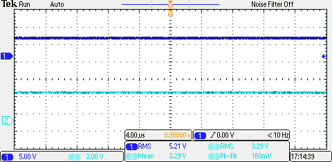
The bottom line is the 3.3V line that is produced from the regulator on the PDS. As you can tell it is not level and oscillates a bit. The peak to peak is at 1.44V which is a very dirty power line. To fix this I added a 1uF capacitor to the 3.3V line which generated the following power signals.
The 3.3V line now has a peak to peak of 160mV which is pretty good. I tried a 10uF capacitor to see if this could be improved but I received the same results. The PDS V1.2 will need to have a 1uF capacitor added to the board before production. This will be added via dead bug technique to the PDS V1.1 boards.
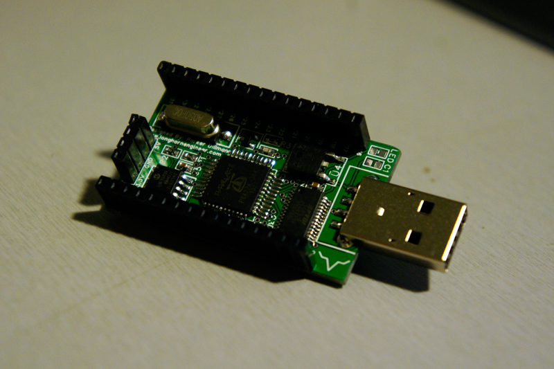
I just finished soldering the first Prop Dev Stick and tested it. After installing the FT232 drivers I was able to program the propeller straight from the Propeller Tool. Serial Terminal has also been tested.
I am going to be shipping a couple of these for testing. If you do embedded systems or mess around with micro controllers I would like for you to test it out. I am offering a fully working and soldered board for just the price of parts alone ($20). Simple stuff like usability, durability, and performance will need to be tested in real life scenarios before I move it into production.
The verilog code is almost fully debugged. The demo code that will run on a Parallax Propeller is in the works. Right now the demo is fairly basic. Today I wrote a C program that takes a 4-bit bitmap image and strips out the header and and converts it to a 2-bit image. It then reorientates the data so the image is “correct”. Bitmap images data reads the image from bottom left to top right. This is essentially backwards. So the program corrects this which means less work for the microcontroller and faster transmission of pixels.
So I changed the font of the site and tweaked the hell out of the backend. Hopefully everyone sees a performance increase on there end. I also changed the colors a bit to remove allot of the orange.
So I think I have been bitten by the FPGA bug. I ordered the DE0 board from Altera this morning. Should arrive by this weekend. I have been thinking of doing a “begineer series” on FPGAs much like how the Arduino introduces people into the world of microcontrollers. Would people be interested in that?
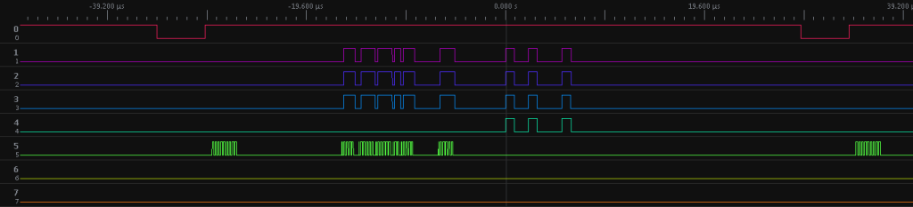
I have been wanting to do this for awhile but have not gotten around to it. I took my Open Bench Logic Sniffer and sniffed the e (in picture from top to bottom) of the Atari 7800 MARIA chip. This is what the signal looks like before it goes into the video mod (D/A converter).
I am still learning how this translates into a picture on the screen. If anyone has any insight into this let me know.