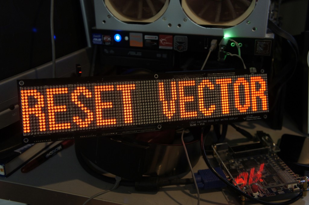
Pulled RESET VECTOR’s 96×16 DMD out of the parts bin and managed to find the old code to get it working again. Going to turn it into a Twitter Feed/Clock/Weather wall thing.
All posts by Parker
DE0 Digital I/O Wing Expansion REV0 Complete
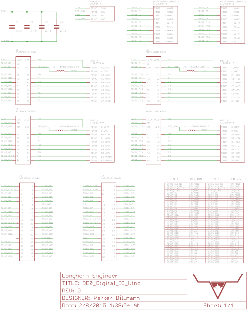
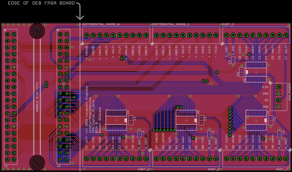
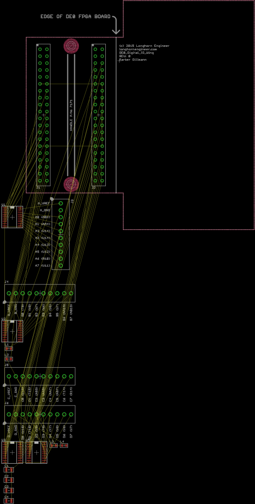
Design ended up having only 10 LVDS signals broken out as that required less unique parts. The connectors are expensive (1-282834-0) running ~$5.70 in singles. I will be looking into alternatives to see if I can get the cost down. I found some on AliExpress but I will need to order them and test them to see if they are any good.
I also included a 4 position auxiliary power connector to power up external circuits. No power safety though (fuses/TVS) so use at your own risk!
DE0 Digital I/O Wing Expansion
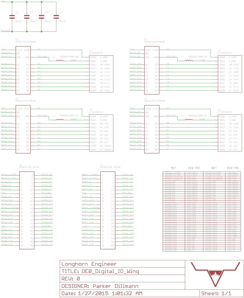
Started work on a expansion board for the DE0 FPGA development board. Planning on having 4 8-bit bi-directional level shifters giving 32 I/O and breaking out 12 LVDS signals to screw terminals. Basically a simple digital acquisition add on. Using the expansion template I made for the DE0 a couple days ago.
LVDS will be buffered to protect the FPGA. Have not picked the buffer chip yet. The bi-directional level shifter is the SN74LVC8T245PWR by Ti. Handles 1.65V to 5.5V on both sides and has basic ESD protection. I am debating putting over voltage protection on the I/O of the level shifters. A 50ohm resistor in series with the I/O plus a 5.6V TVS Diode should do the trick and not add to much cost to the board.
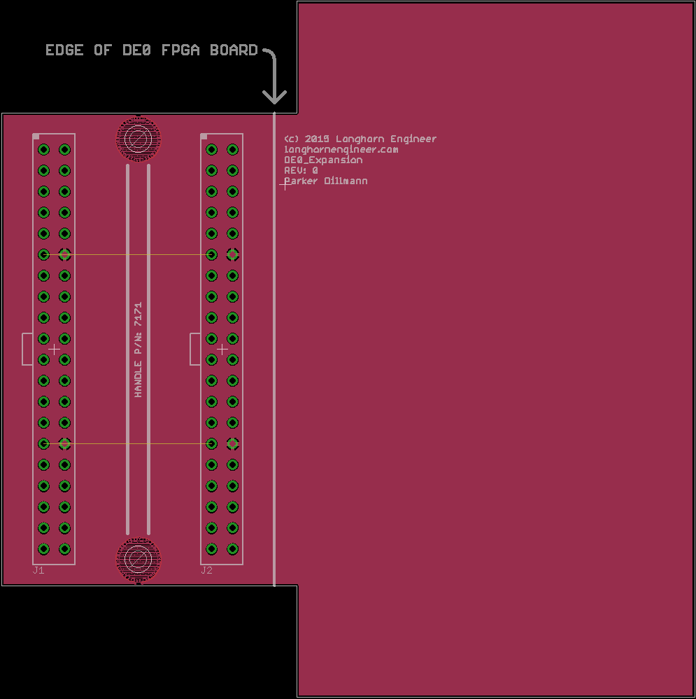
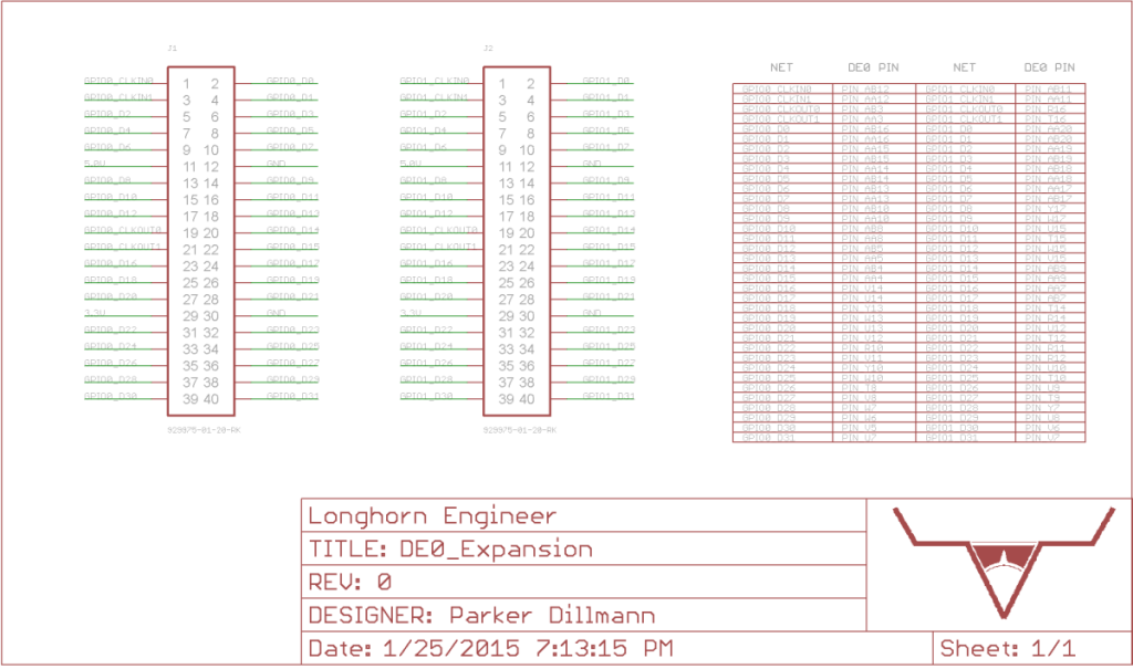
DE0 Expansion Template
Uploaded the template that I use for making hardware expansions for the DE0 FPGA Dev board. It fits on the 2 40Pin GPIO Headers on the right side of the board. Files are for Eagle V6.0+
DE0 VGA Driver
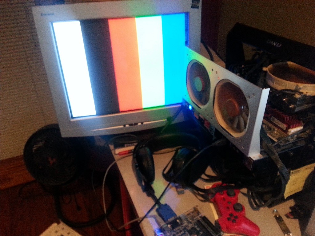
Working on a video driver for the Altera DE0 Development Board by terasIC. The DE0 has a 12bit (4bit per color) resistor ladder DAC that connects to the VGA connector. It is capable of 1280×1024 @ 60Hz officially but I think more is possible.
Find the files in the github repository.
Keg Cooler built from 49″ Milk Cooler
Been working on this Keg Cooler the past couple weekends. I picked up a 49″ Milk Cooler on craigslist. It is all stainless construction and has a commercial grade compressor. Very robust.
Five taps on the front. Four for regular CO2 delivery and one nitro tap. Each of the taps have individual control over the serving pressure.
The kegs are accessible from the back. There is enough space for double the amount of kegs but I wanted room for coldcrashing my brews.
This is how the doors open up. I will be adding chain to the lower doors so they cant swing all the way down and damage the taps.
Prop Dev Stick REDUX REV4 Prototypes Complete!
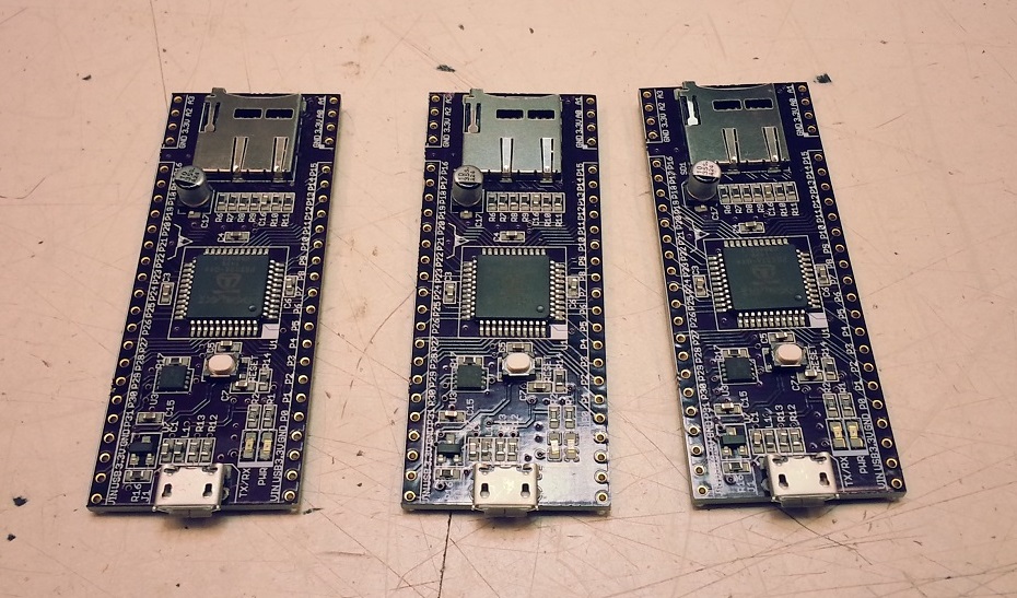
Parts, PCBs, and Stencils arrived earlier this week so I put together the three prototypes for REV4. Above is pre reflow.
Directly after reflow.
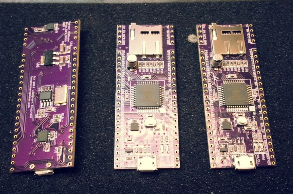
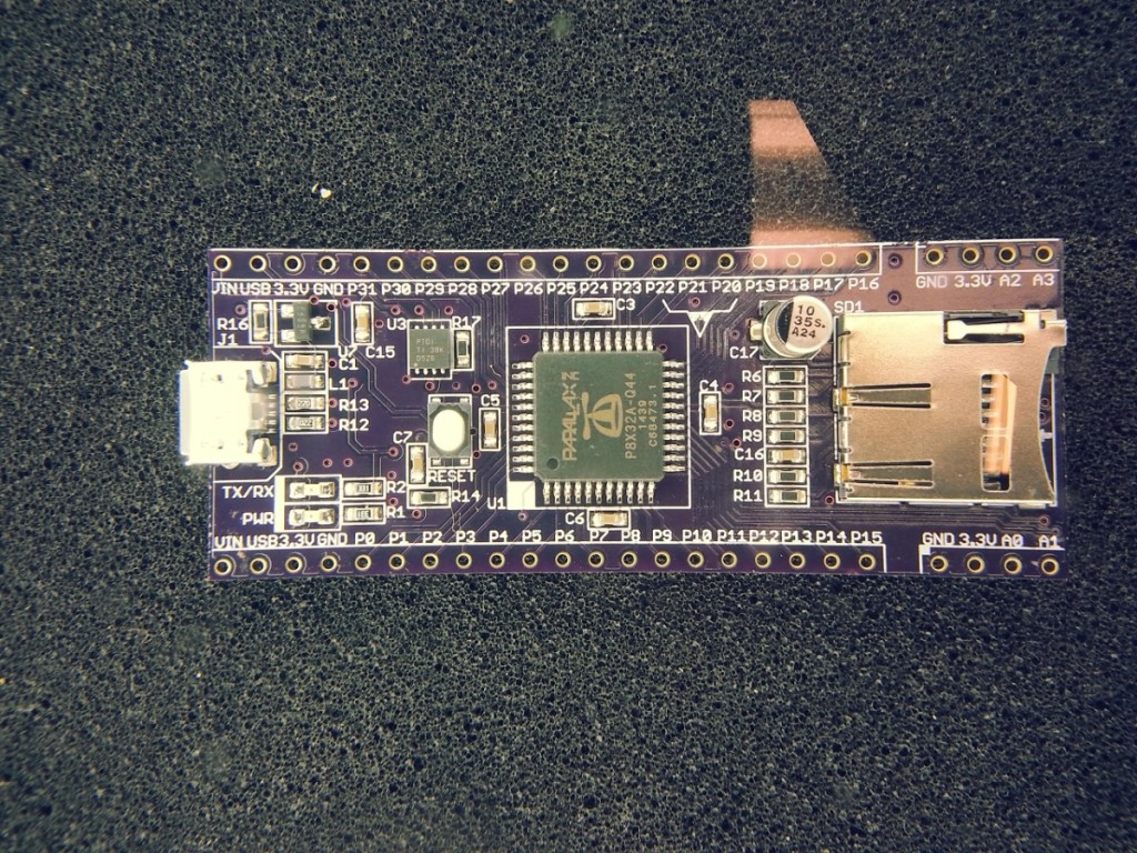
Magnified picture of the board. Turned out great. FTDI chip flashes and Propeller programs over USB. The new MAX11613 ADC works as well. I will be posting the driver code for that shortly.
Prop Dev Stick REV4 Update
Some changes from REV 3 to REV 4.
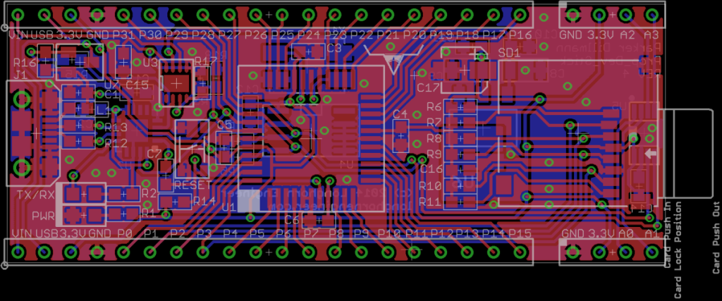
Render of the PCB from OSHPark.
Top stencil pattern. The through hole pads on the micro USB connector are going to be soldered with the “Paste In Hole” method. I have not tried this yet but if it works I will be able to cut out an entire operation during production of the boards.
Propeller Development Stick REDUX REV3
Finished the next revision of the Propeller Development Stick REDUX. The power switching has been changed to fix the flakiness of the past revision. I switched the TPS2115 to a TPS2113. This seems to have fixed the weird power switching issues. The layout has change completely. SD card slot is on the top side of the board and the power circuity and ADC are on the bottom now.
Part tray video, Screen Printer Demo, TQ-100 Pinheck Board
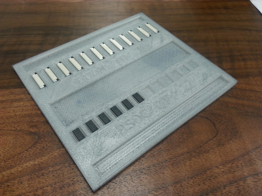
I had a couple spare PSOCs to test the part tray with and train the pick and place. The PSOCs fit very well with little wiggle. Will be training the machine on the placement of the parts on Friday.
Here is a short little video of the pick and place positioning the FCC connectors onto the PCB panel. I am using double sided stick tape to replicate the holding force of solder paste. The pick and place is running at 10% speed to prevent the connector from sliding off the nozzle.
This is the screen printer we are currently using at MacroFab. It is an old semi-automatic printer but it works well for its age. It has a vacuum table to hold down the pcb and suck the screen to the pcb. Put some coated stainless blades on it for smooth paste squeegee action.
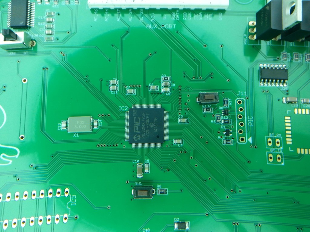
The Pic-32 on the Pinheck Pinball System is a TQ-100 package which is .4mm pitch. We used a solder stencil and placed the part via the pick and place. Stencil was .1mm in thickness. Ran 25 boards and had no solder bridges.

