New Vehicle Acquired. Jeep +1

This past Friday I picked up a 1990 Jeep Grand Wagoneer. It was in Dallas, Tx so I took the Friday off and drove up with my Dad and picked it up. Drove back to Houston with it (~300miles) was a pretty fun road trip!

Wagoneer in the driveway after the long day.

It is a fully loaded Grand Wagoneer with all the trimmings. Everything functions except the rear window wiper and sprayer. The wiper looks to just be a bad wiring and the sprayer is missing from the back. If you know where to get a sprayer let me know….they seem to be unobtainium.

5.9L of raw Murica fury.

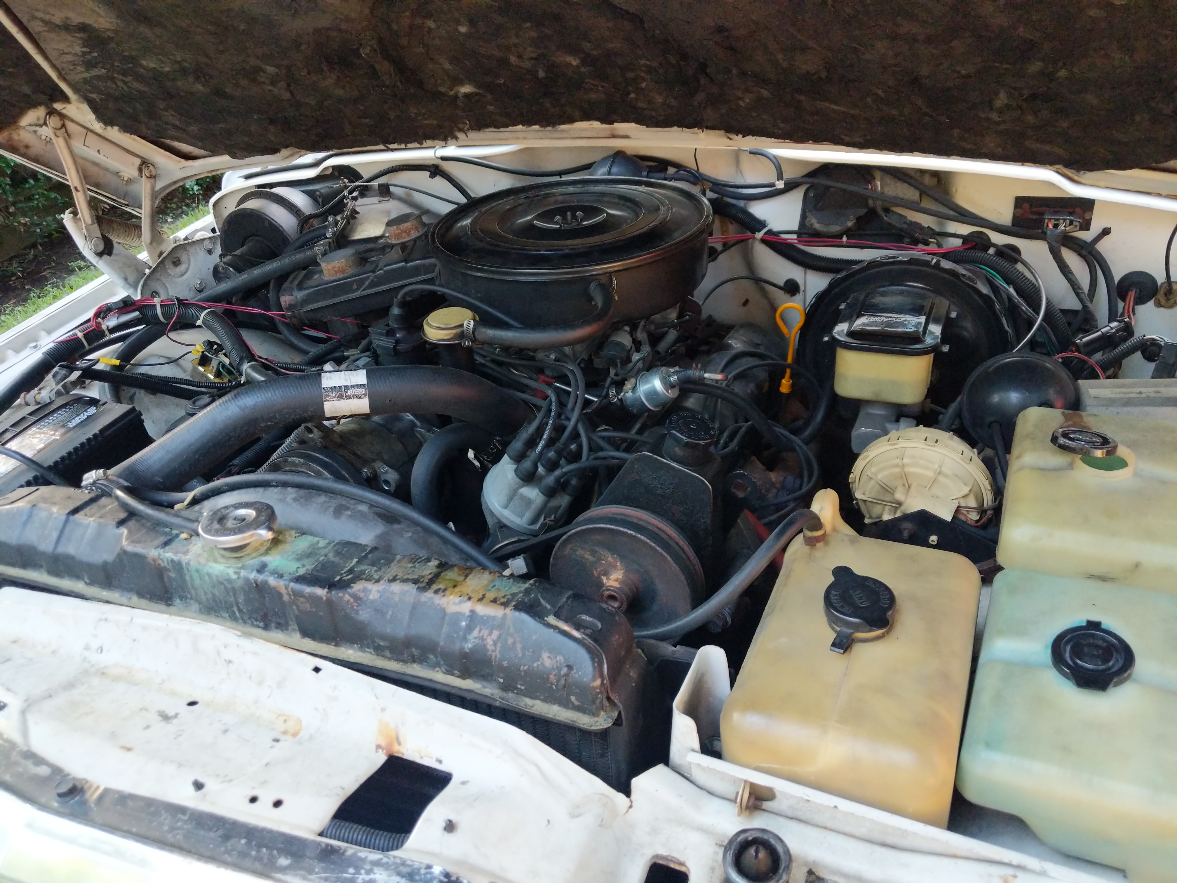
The 5.9L AMC 360 engine is mostly intact and runs ok. The valve seals are blown so the engine smokes a bit on start up.

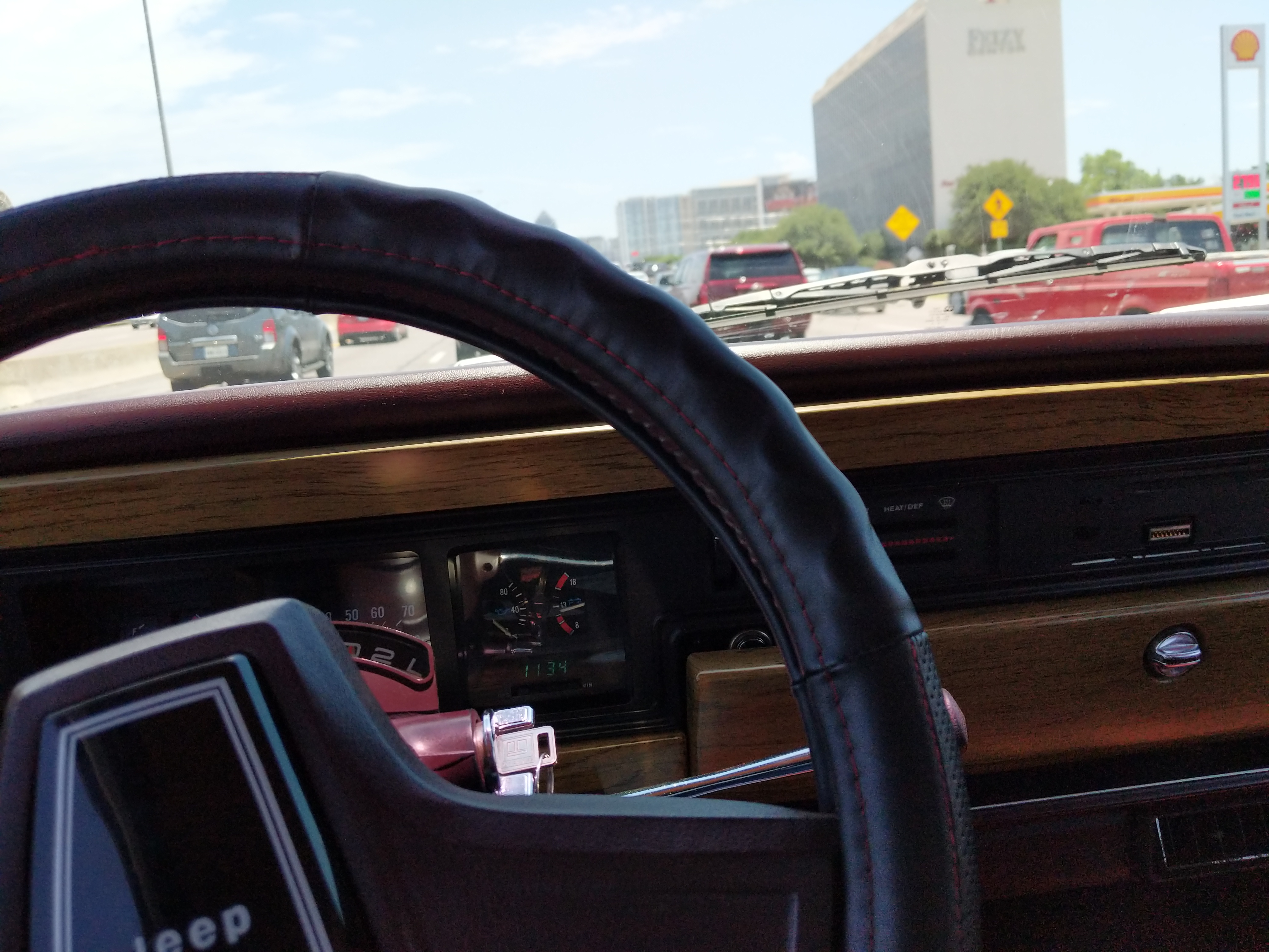
When I got the Wagoneer the oil pressure gauge wasn’t working so I just had to hope it had oil pressure to make it back to Houston.

The first thing I did was an engine oil flush and replaced the oil pressure sender and wire. Engine idles at 40psi cold and ~10psi hot. The hot 10psi is not ideal but it does have 188K miles on it. I am debating rebuilding the oil pump or just leaving it.

Stuck in Dallas traffic after picking up the Wagoneer.

My long term plan with the Wagoneer is to not 100% restore it but just make it nice. Fix all the problems, modernize the electronics, and swap in a LQ4 V8 engine and 4/5 speed automatic transmission. To get there however will take time.

My short term goal is to turn it into a decent daily driver and rock the AMC 360 engine while I fix the major problems and figure out how much I want to restore.

Here is the “short term” list.

  • Cooling System
    • Radiator has a cracked filler neck. Fix the copper/brass radiator by soldering/brazing the crack
    • Replace T-stat
    • Replace Water Pump
    • Flush System
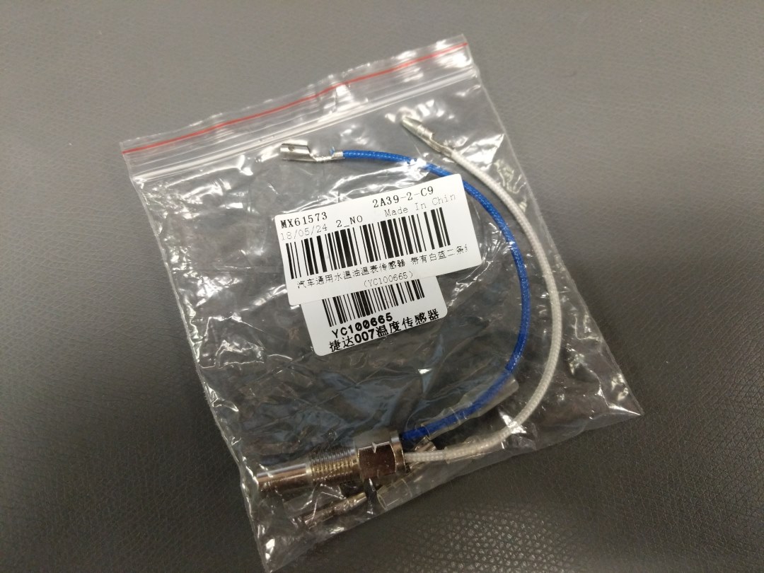
    • Replace temperature sender
  • Engine
    • Another engine oil flush
    • Open valve covers to check rockers and push rods
    • New spark plugs
  • Transmission
    • Oil flush
    • New filter
    • New fluid
  • Fuel System
    • Repair gas tank skid
    • Clean tank
    • Replace rubber hoses and steel if needed
    • New fuel sending unit
    • Tank vent and hoses replacement
    • New fuel filter
  • A/C (very important!)
    • Recharge R12
    • Fix electrical
  • Steering
    • Replace leaking steering gear box
    • New hydraulic hoses
    • New fluid for power steering
    • Ball joints
    • Tie rod ends
  • Suspension
    • Replace sagging leaf springs with new suspension
  • Drivetrain
    • Flush and replace oil in transfer case
    • U-Joints
    • Rebuild Axles
King enjoying the Wagoneer.

Sounds like a lot but afterwards it should be a nice daily. The Wagoneer already rides like your sofa going 70mph down the freeway so it can only get better!

MAX6682 Breakout Board and Reading Thermistors

To read oil and coolant temperature on the Jeep I wanted to use automotive parts for the sensors. Most temperature sensors in the automotive world are thermistors. I searched around for some in 1/8″ NPT and found some designed for aftermarket gauges. Only problem was there was no datasheet for them…which is necessary to accurately read the thermistors since they are non linear devices. At under $4 a piece I ordered them  anyways.

Thermistors with part number MX61573 and YC100665.


Fortunately when they arrived they had a part number on them and after some googling I managed to find a temperature chart.

Temperature to resistance chart for the MX61573 Thermistors
Temperature to resistance chart for the MX61573 Thermistors.


I double checked the values with a multimeter and setting the hot air gun to the temperatures in the chart above and seeing what the resistance was. Everything matched.

To read the thermistors I decided to use the MAX6682 IC. This IC gets rid of power supply noise and thermal self heating of the thermistor.

The only thing I had to calculate was the REXT value. I used the 2031 ohm (20C) for RMAX, 108 ohm (100C) for RMIN, and 388 ohm (60C) for RMID. This came out to a value of 287 ohms.  Which the resistor ERA-3AEB2870V by Panasonic works. See page 6 of the datesheet for the formula to calculate REXT.

Then I drew up the schematic and layout for the breakout board.

Schematic for the MAX6682 Breakout Board.
Layout for the MAX6682 Breakout Board.


I added a little header (J3) that will allow me to easily change the REXT value for other thermistors.

MacroFab PCB Render.


Boards ordered!


ABCC or Automotive Butt Climate Control

Climate controlled seats in your car are probably one of the greatest inventions since sliced bread if you live down in humid hot climates (like Houston!). Since trying them out in my Dad’s Tahoe years ago I have always wanted them in my Jeep but no one really makes after market seats that have them and there are no “kits” like adding heating elements to seats.

This changes now!

2015 Ford F-150 seat climate control module.

I managed to snag a 2015 Ford F-150 seat climate control module unit on ebay for $40. I picked this unit cause it looked compact and looking at the wiring from pictures I found on the internet it looked like I could reasonably make this work.

Ford wiring diagram for climate controlled seats. Looks simple enough!

So how these work is via the peltier effect. The peltier unit has two copper heatsinks attached, one for each side. When voltage is applied to the peltier unit one side gets hot and the other cold. This is transferred to the copper heatsinks where the fan blows creating a stream of lava hot air and arctic frost air.

Exhaust port of the unit. This is typically vented back into the cabin under the seat or goes into the climate control system of the vehicle.
This port goes into the tubing that goes into the seat cushion. Depending on the polarity of the peltier it can be hot or cold.

This is the peltier unit removed from the housing. The blue and yellow wires ended up being the peltier unit and after some testing the green and gray wires seem to be a NTC 200K thermistor. With 12V on the peltier in heating mode the resistance is 54K ohms. With 12V on the peltier in cooling mode it is 240K ohms. Room temperature resistance is around 170K ohms.

Peltier unit top.
Peltier unit top.
Peltier unit bottom.

The fan is interesting. There are three wires. Red, black, and white. I figured red is power (12V), black is ground, and white is a pulse that I can measure and find the RPM for feedback control similar to the thermistor on the peltier.

Fan part of the Ford module.

Wired up the fan with 12V on red and ground on black. No go. Attached the white wire to 12V and it spun up! Pulling 1.4 Amps. Cool. Then the red wire fell off the wire clip and it was still spinning. 12V on the white wire (still at 1.4A!) and nothing on the red…. Weird.. Why is that? Maybe the red wire was feedback? Looking at the signal on the scope proved that was not the case. Time to open it up!

Interesting construction of the fan.

I took the fan out of the plastic housing. Looks like the PCB is directly on the aluminum or steel backing plate? The blades/cage of the fan is attached with a blind c clip in a bronze bushing on the back of the fan. This was pretty difficult to remove but a sharp pick and screwdriver I managed to remove it.

The PCB exposed. TELL ME YOUR SECRETS!

Yup! The PCB is on an aluminum or steel substrate (need to check which one) instead of the typical FR4 base. All single sided routed.

Red wire is labeled VM, Black is GND, and the White wire is VSP. I manged to get a part number from the large IC labeled IC1 on the upper right. The LB11988 is a brushless motor controller from On Semiconductor. T1 is labeled 065886A and is a DPAK package. I dunno what this part is at this point. Looking at DPAK mosfet parts the pinout makes sense. It also could be a large BJT. I then drew up a schematic.

Fan power front end schematic.

The VCC pin on the LB11988 powered the internal control circuitry for the IC and VS is the motor power from I can gather. The datasheet is a bit vague here.

If the Red wire is disconnected the White wire provides all the power to the motor. That means that the T1 part either has a blown gate if its a mosfet (mosfets are not supposed to pull significant or any power through the fate) or T1 is a BJT with crazy base junction current.

I removed the T1 part and tested so see if it was a BJT and sure enough I was able to measure the diode effect from base to collector and base to emitter. Looking at DPAK BJTs that are automotive grade shows that some of them can have up to 2A of base current….Checks out I suppose!

With the mysterious of the unit solved it is time to develop a controller for it. I have read that the peltiers used in these units are powered via 16V but I can not confirm. Maybe a 12V -> 16V step up is needed that is rated for 8A. Lots of power need :)

Honda ATC110 engine stand complete and running

I was able to get the engine stand completed and engine running again.

Cheapo moped muffler and beer!

The old exhaust system was pretty much cracked and fell apart when I tried to remove it from the three wheeler so I had to make a “new” setup. I bought the cheapest muffler I could find on eBay ($15 moped muffler) and some spare steel tubing I had and I welded up a temporary exhaust. I reused the old exhaust flange that mounts to the engine but I would like to replace all of it with new material when I finally transplant this engine in the go cart.

Straight exhaust setup reusing the original header flange and some spare tubing. Ugly but it works.

I then mounted the fuel tank I bought on ebay for $6. Fairly tiny with only 1L of capacity but the tank was pretty cheap and doesn’t leak… can’t complain about that.

1L fuel tank, hoses, and fuel filter from ebay.

I made the fuel tank mount out of some old aluminum sign material I had forever. I think I have been holding onto that material for over a decade now! Knew it would be useful some day :)

Fuel tank mounted on the engine stand.

The fuel tank mount is designed to be unscrewed giving me more access to the engine when I start disassembly.

And it fired right up after filling the tank up. Glad I got the wiring right!


What is next is to disassembly and clean the entire engine. Once it heats up it smokes pretty good so I will need to at the minimal replace the piston rings and lap the valves. Probably end up honing the cylinder walls for the new rings.

Compressor IoT Project

At MacroFab we have a large industrial air compressor that provides compressed air to our pick and place and various machines.  I want to monitor the compressors pressure and run time to help influence the maintenance schedule for it.

Stephen and I talked about the Compressor IoT project on the following Podcasts: MEP EP#68, MEP EP#70, and MEP EP#74.

Compressor IoT part list

  • LSM9DS1
    • IMU for vibration sensing
    • iNEMO inertial module: 3D accelerometer, 3D gyroscope, 3D magnetometer
    • 3.3V, I2C
  • SPU0410HR5H-PB
    • MEMS Microphone
    • 3.3V
    • Analog signal, will be boosted with an opamp
  • TMP102
    • Board Mount Temperature Sensors Low Power Digital Temp Sensor
    • 3.3V, I2C
  • Ebay Pressure Transducer
    • 1/8″ NPT Male fitting
    • 5.0V
    • Analog output 0.5V – 4.5V over pressure range
  • 6225AXXSZS-DC3
    • SSR to control the compressor switch
    • 3VDC to 32VDC control signal
    • Place 10ohm in series from pin from particle photon for protection.
    • TVS 3.3V for transient protection.
  • 1591XXSFLBK
    • Enclosure with flange
  • Particle Photon
    • IoT platform
Compressor IoT Schematic


Compressor IoT Layout

You  can find the files on my github.