
Climate controlled seats in your car are probably one of the greatest inventions since sliced bread if you live down in humid hot climates (like Houston!). Since trying them out in my Dad’s Tahoe years ago I have always wanted them in my Jeep but no one really makes after market seats that have them and there are no “kits” like adding heating elements to seats.
This changes now!
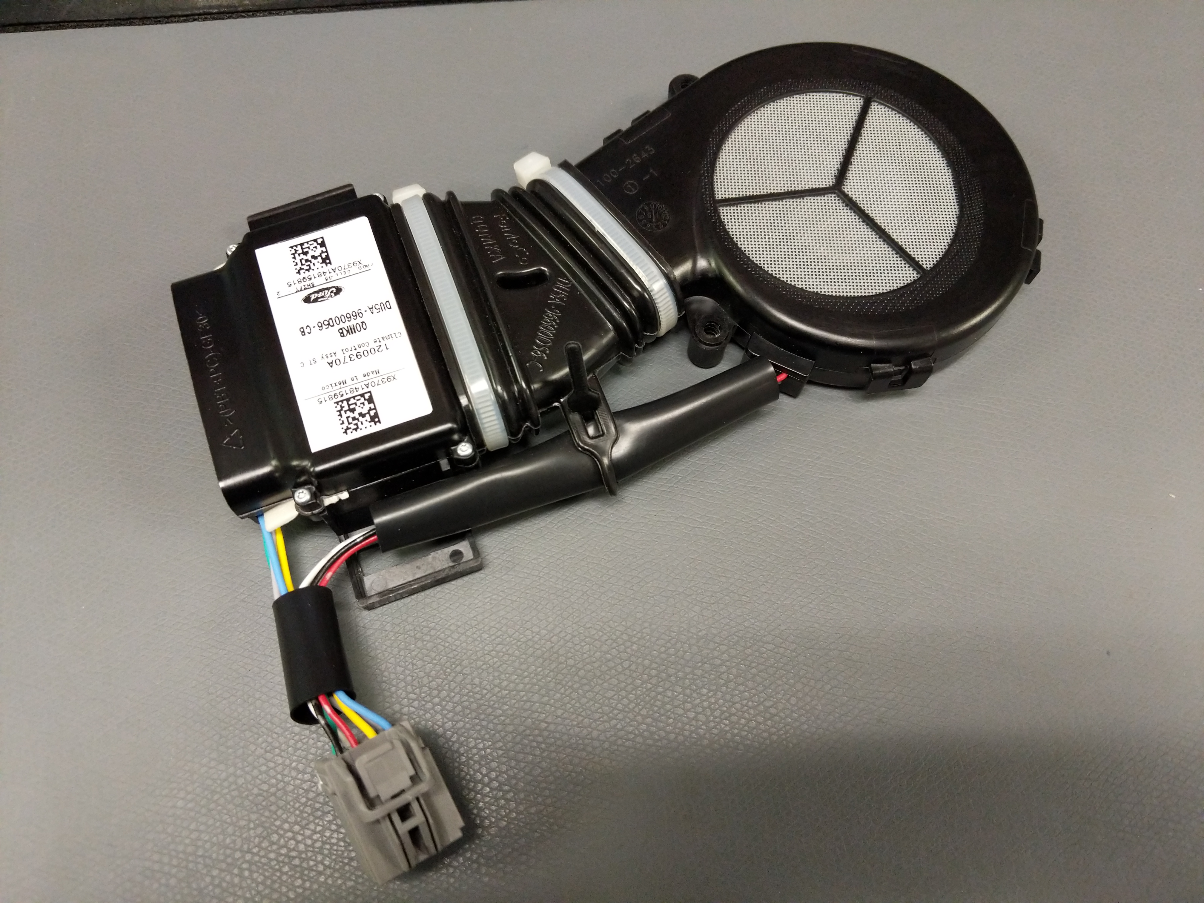
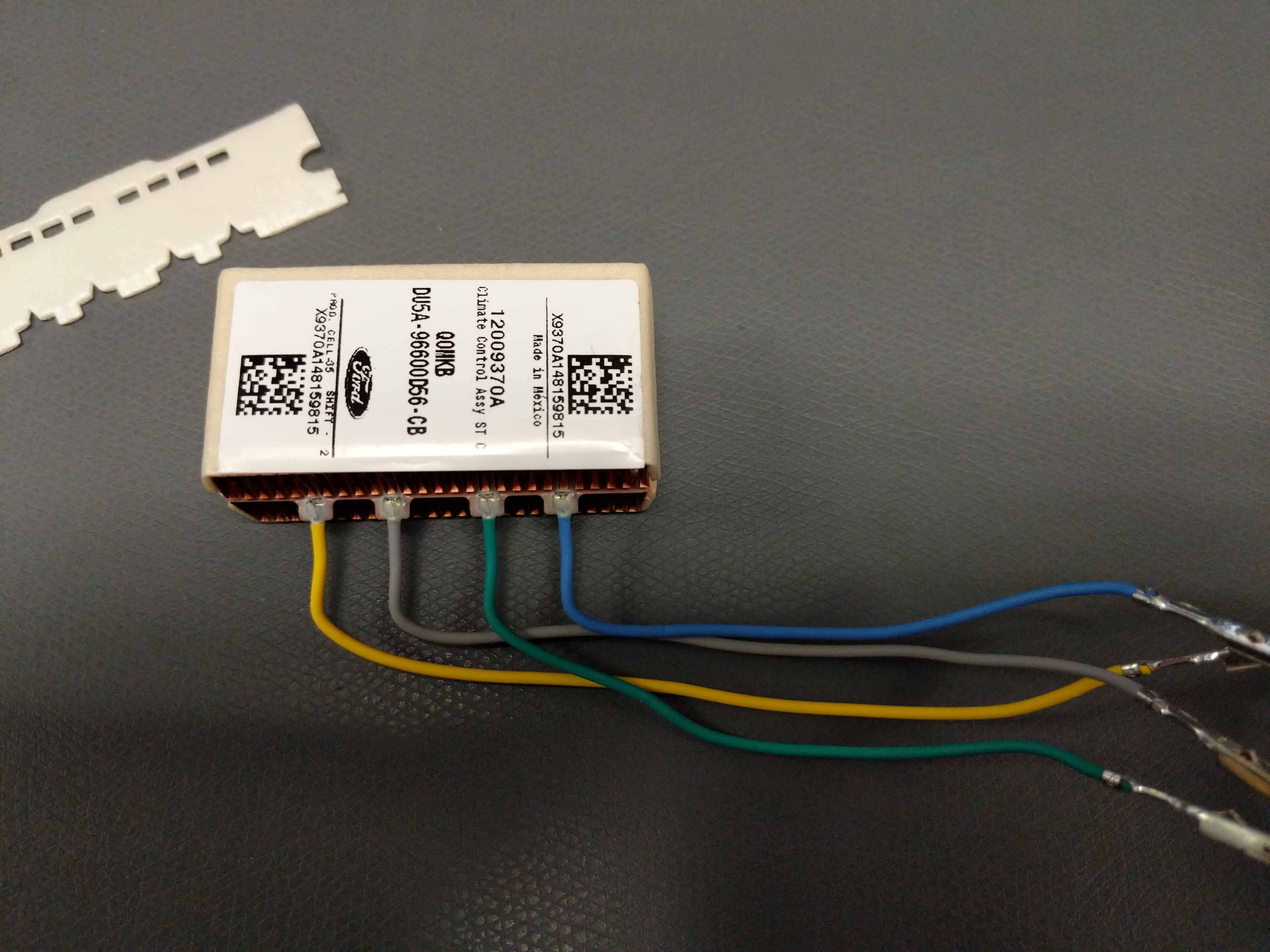
I managed to snag a 2015 Ford F-150 seat climate control module unit on ebay for $40. I picked this unit cause it looked compact and looking at the wiring from pictures I found on the internet it looked like I could reasonably make this work.
So how these work is via the peltier effect. The peltier unit has two copper heatsinks attached, one for each side. When voltage is applied to the peltier unit one side gets hot and the other cold. This is transferred to the copper heatsinks where the fan blows creating a stream of lava hot air and arctic frost air.
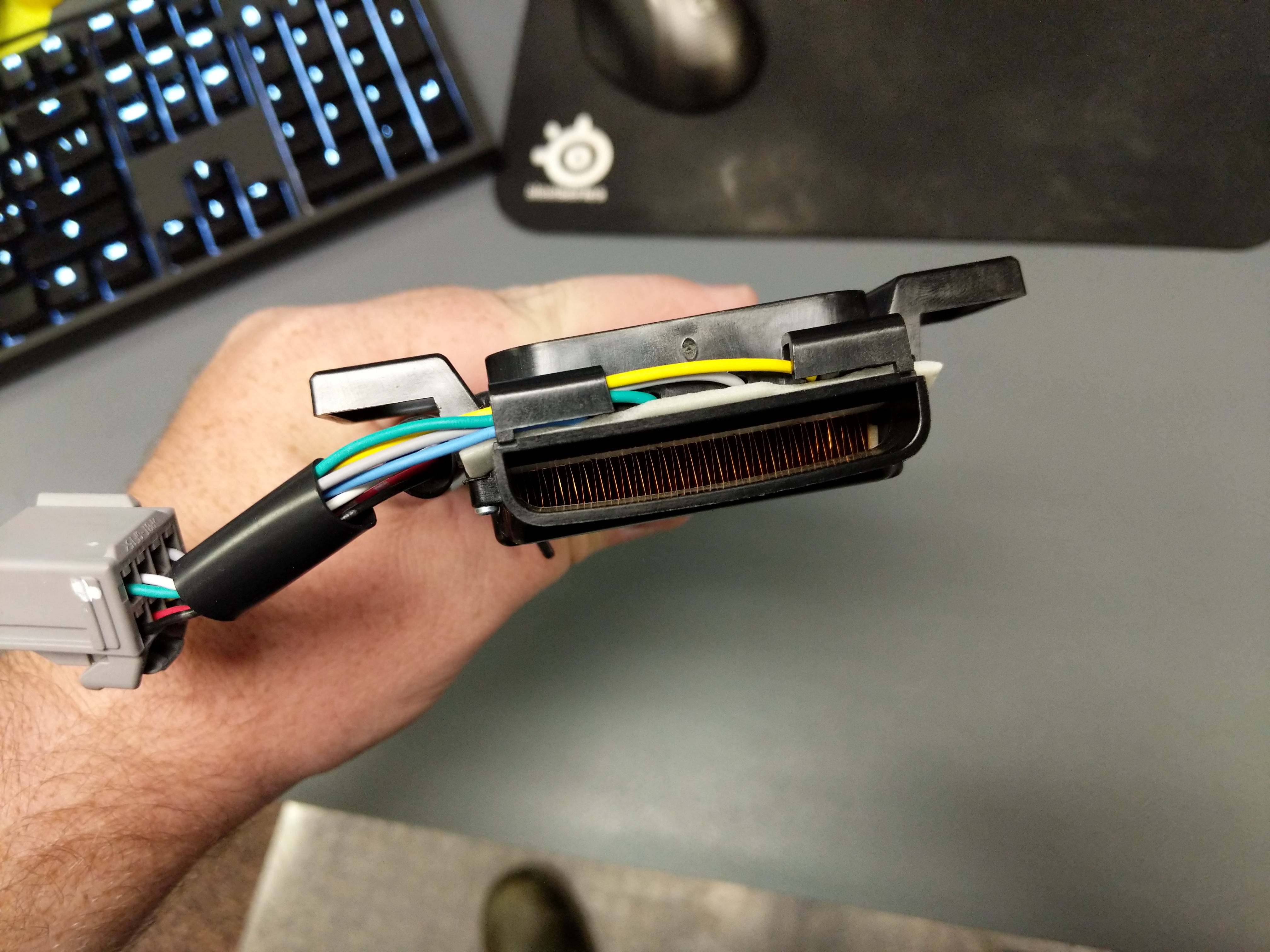
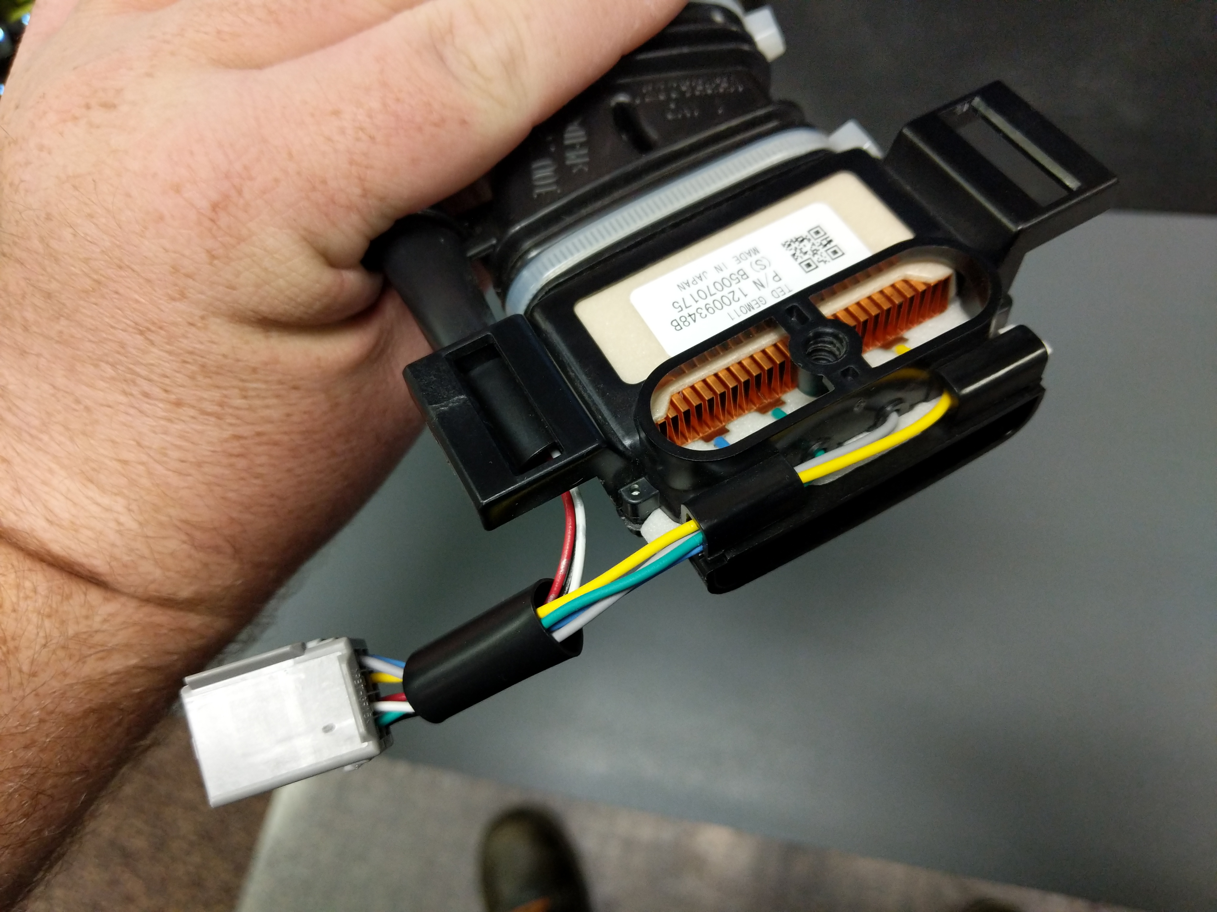
This is the peltier unit removed from the housing. The blue and yellow wires ended up being the peltier unit and after some testing the green and gray wires seem to be a NTC 200K thermistor. With 12V on the peltier in heating mode the resistance is 54K ohms. With 12V on the peltier in cooling mode it is 240K ohms. Room temperature resistance is around 170K ohms.

The fan is interesting. There are three wires. Red, black, and white. I figured red is power (12V), black is ground, and white is a pulse that I can measure and find the RPM for feedback control similar to the thermistor on the peltier.
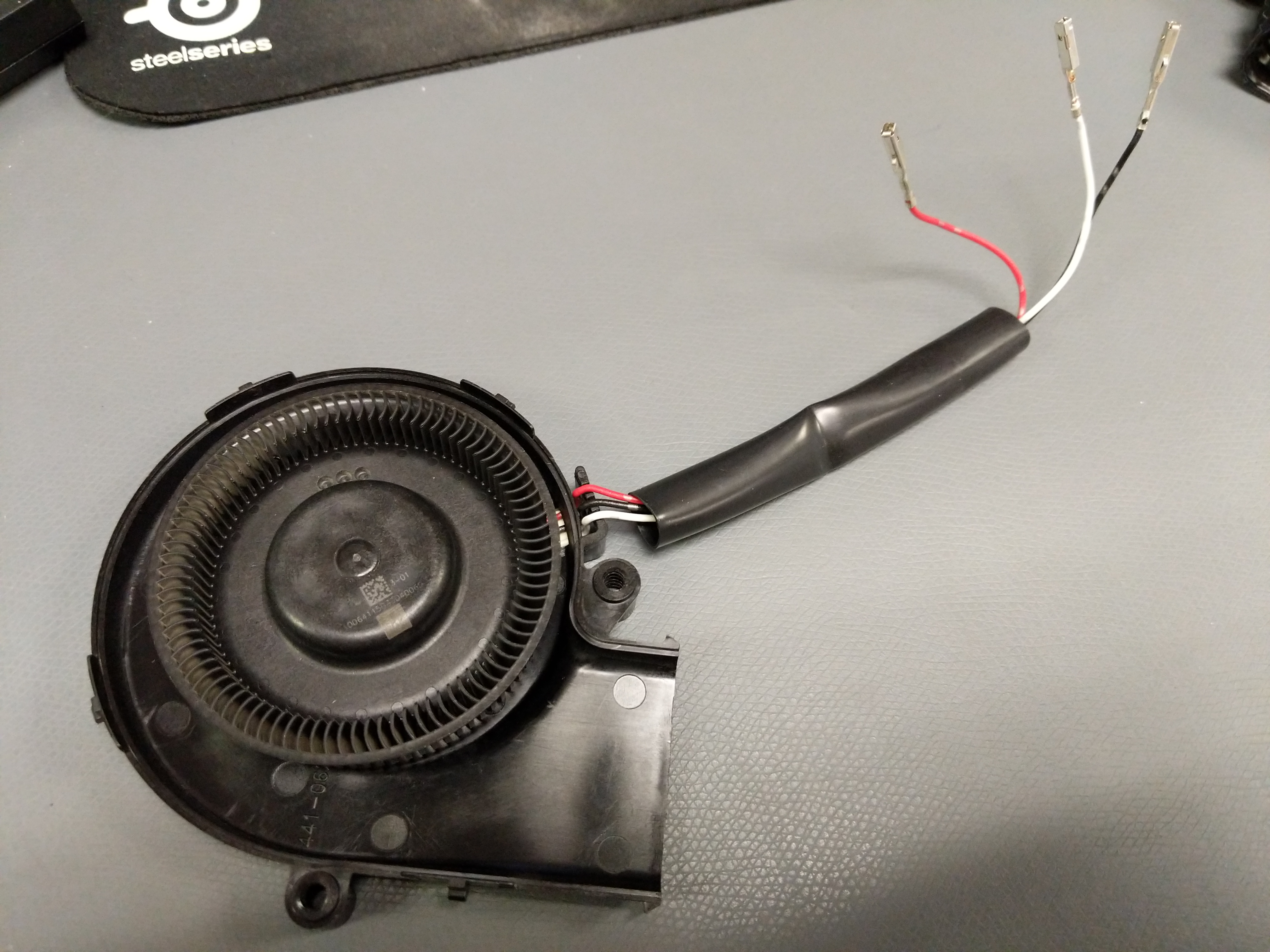
Wired up the fan with 12V on red and ground on black. No go. Attached the white wire to 12V and it spun up! Pulling 1.4 Amps. Cool. Then the red wire fell off the wire clip and it was still spinning. 12V on the white wire (still at 1.4A!) and nothing on the red…. Weird.. Why is that? Maybe the red wire was feedback? Looking at the signal on the scope proved that was not the case. Time to open it up!
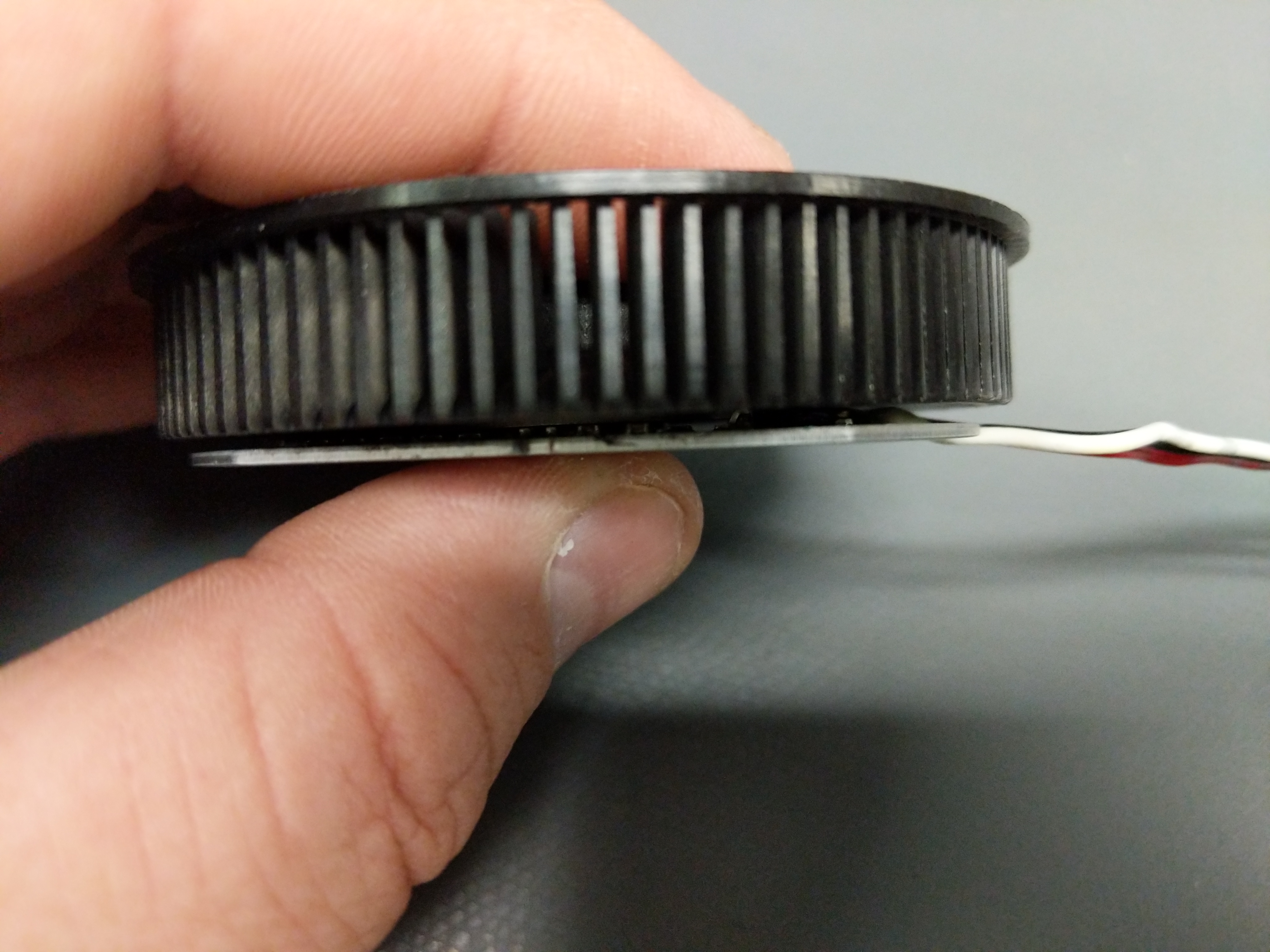
I took the fan out of the plastic housing. Looks like the PCB is directly on the aluminum or steel backing plate? The blades/cage of the fan is attached with a blind c clip in a bronze bushing on the back of the fan. This was pretty difficult to remove but a sharp pick and screwdriver I managed to remove it.
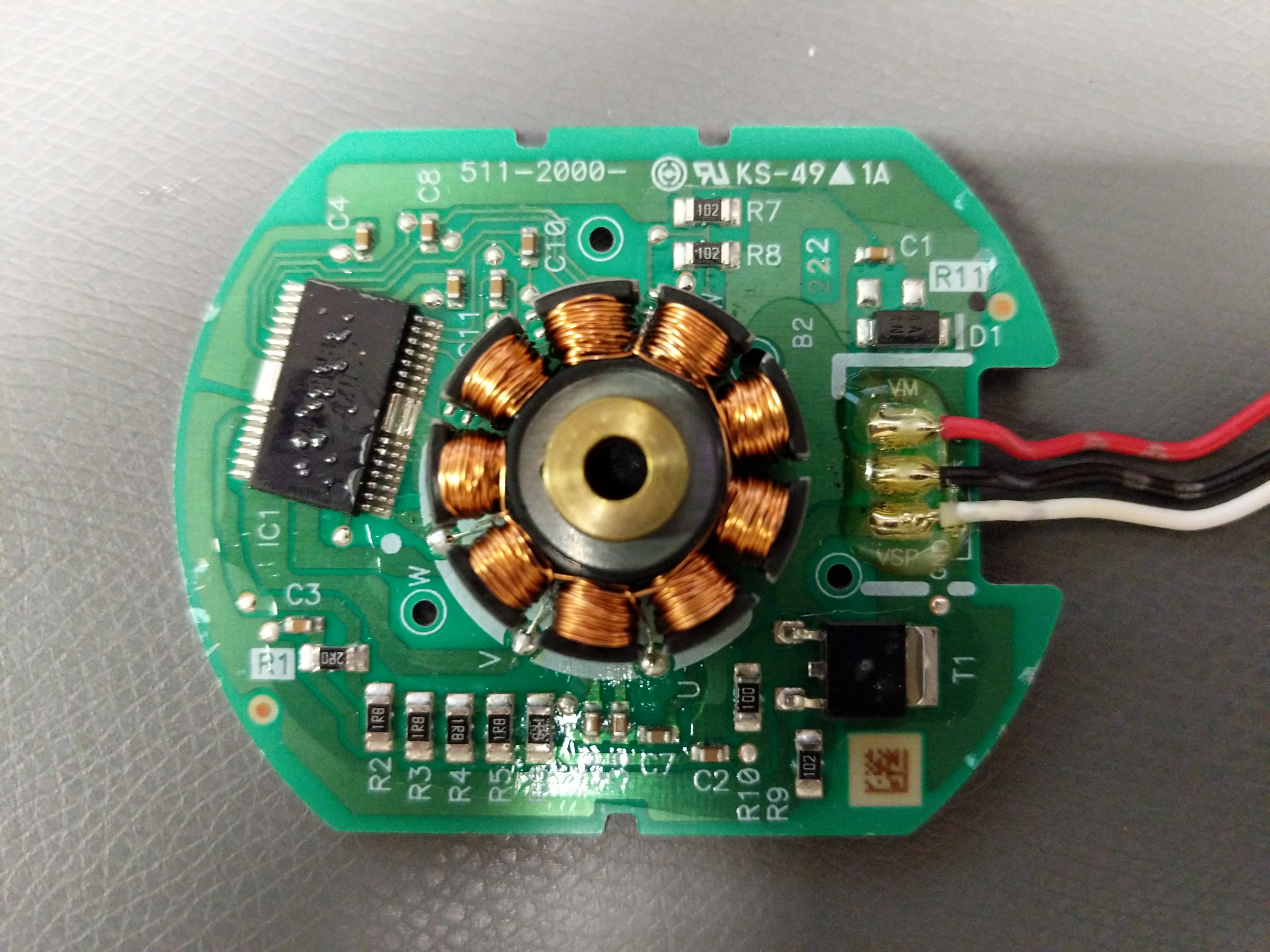
Yup! The PCB is on an aluminum or steel substrate (need to check which one) instead of the typical FR4 base. All single sided routed.
Red wire is labeled VM, Black is GND, and the White wire is VSP. I manged to get a part number from the large IC labeled IC1 on the upper right. The LB11988 is a brushless motor controller from On Semiconductor. T1 is labeled 065886A and is a DPAK package. I dunno what this part is at this point. Looking at DPAK mosfet parts the pinout makes sense. It also could be a large BJT. I then drew up a schematic.

The VCC pin on the LB11988 powered the internal control circuitry for the IC and VS is the motor power from I can gather. The datasheet is a bit vague here.
If the Red wire is disconnected the White wire provides all the power to the motor. That means that the T1 part either has a blown gate if its a mosfet (mosfets are not supposed to pull significant or any power through the fate) or T1 is a BJT with crazy base junction current.
I removed the T1 part and tested so see if it was a BJT and sure enough I was able to measure the diode effect from base to collector and base to emitter. Looking at DPAK BJTs that are automotive grade shows that some of them can have up to 2A of base current….Checks out I suppose!
With the mysterious of the unit solved it is time to develop a controller for it. I have read that the peltiers used in these units are powered via 16V but I can not confirm. Maybe a 12V -> 16V step up is needed that is rated for 8A. Lots of power need :)