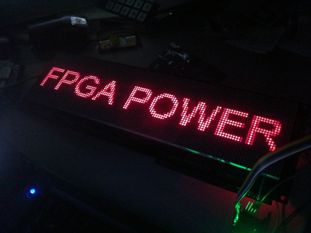
So I finally finished the prototype of the 128 x 32 Light Emitting Diode Dot Matrix Display V1.0 (LEDDMD). The protocol to write to the display is almost exactly like a shift register. There is a clock, latch, and data lines. It works in either 1 bit mode or 8 bit mode data line modes.
In 1 bit mode there is only 1 data line and in 8 bit mode this is 8 data lines. 8 bit mode enables you to clock in an entire byte of data at a time speeding up the transfer process by a factor of 8. In either mode you can do animations smoothly. All processing of the data is done on the microcontroller. The Display stores the data and takes care of running the display.
The bulk of the hardware is in the FPGA. I am using a Cyclone II EP2C8Q208C8N FPGA breakout board. There are some darlington transistor arrays that sink the current from a single row. To expand the I/O of the FPGA some decoders are used.
Here are the links to all the code:
FPGA:
Main Routine
Memory
Propeller:
Transmission Protocol and Test

