
Fixed an old bug in some RESET VECTOR DMD display code for multiple lines and got the above demo working. I will have to port the prop code to python however to make my twitter wall thingy.

Fixed an old bug in some RESET VECTOR DMD display code for multiple lines and got the above demo working. I will have to port the prop code to python however to make my twitter wall thingy.
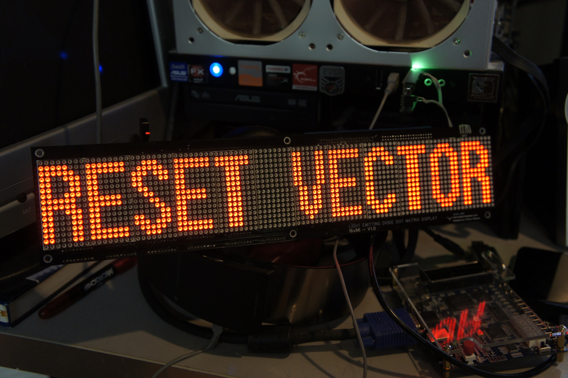
Pulled RESET VECTOR’s 96×16 DMD out of the parts bin and managed to find the old code to get it working again. Going to turn it into a Twitter Feed/Clock/Weather wall thing.

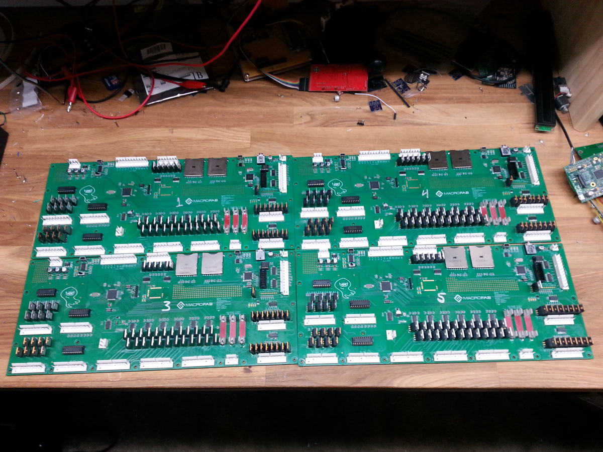
Last week I finished the prototypes for the REV 5 Pinheck Board and shipped them to Spooky Pinball. I built 5 boards for testing to make sure this is the final revision before starting the full on production run. These will be in the machines Spooky is taking to the Midwest Gaming Classic. I will also be there encase anyone has questions about the board set.

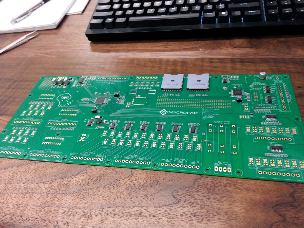
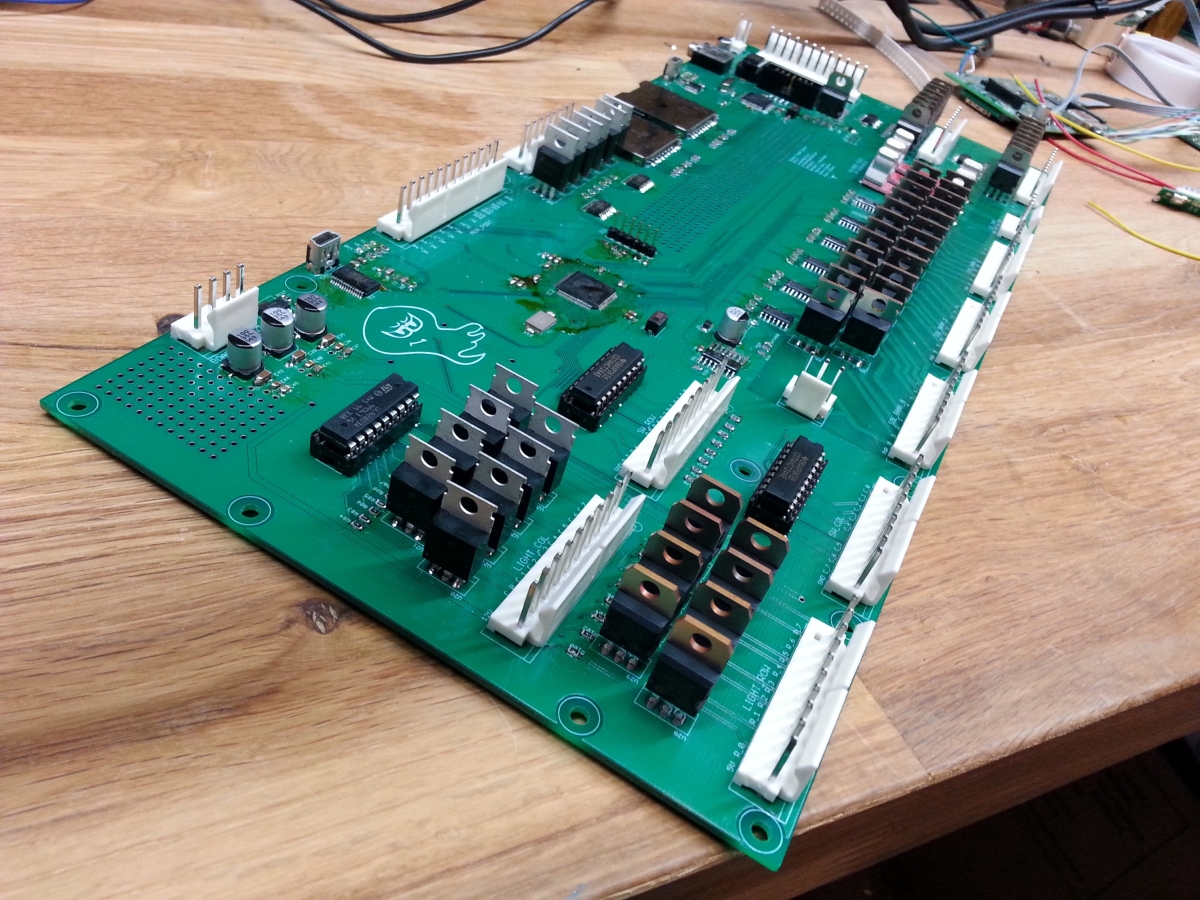
Second prototype board I finished.
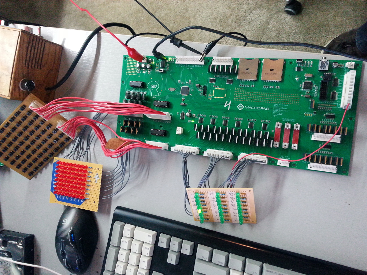
Test jigs to make sure the boards are made correctly. I am working on a better test jig for the production run that will be fully automated to help speed up the testing process.
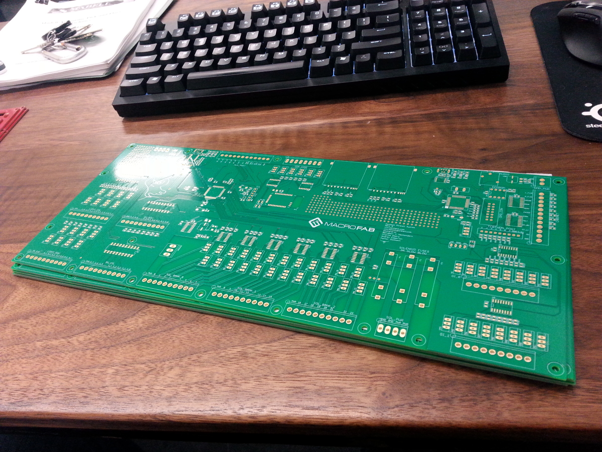
Boards ready to ship!
These are the first 5 test boards to make sure the changes from the REV4 board we done correctly. Since I am pretty sure this is the final revision I ordered the boards on FR4 170TG and ENIG finish. 170TG is higher temperature rated substrate which allows for lead free reflow without scotching the board. ENIG finish is a higher quality finish for the pads over HASL as it tends to be flatter and more consistent which is nicer on the pick and place machines.
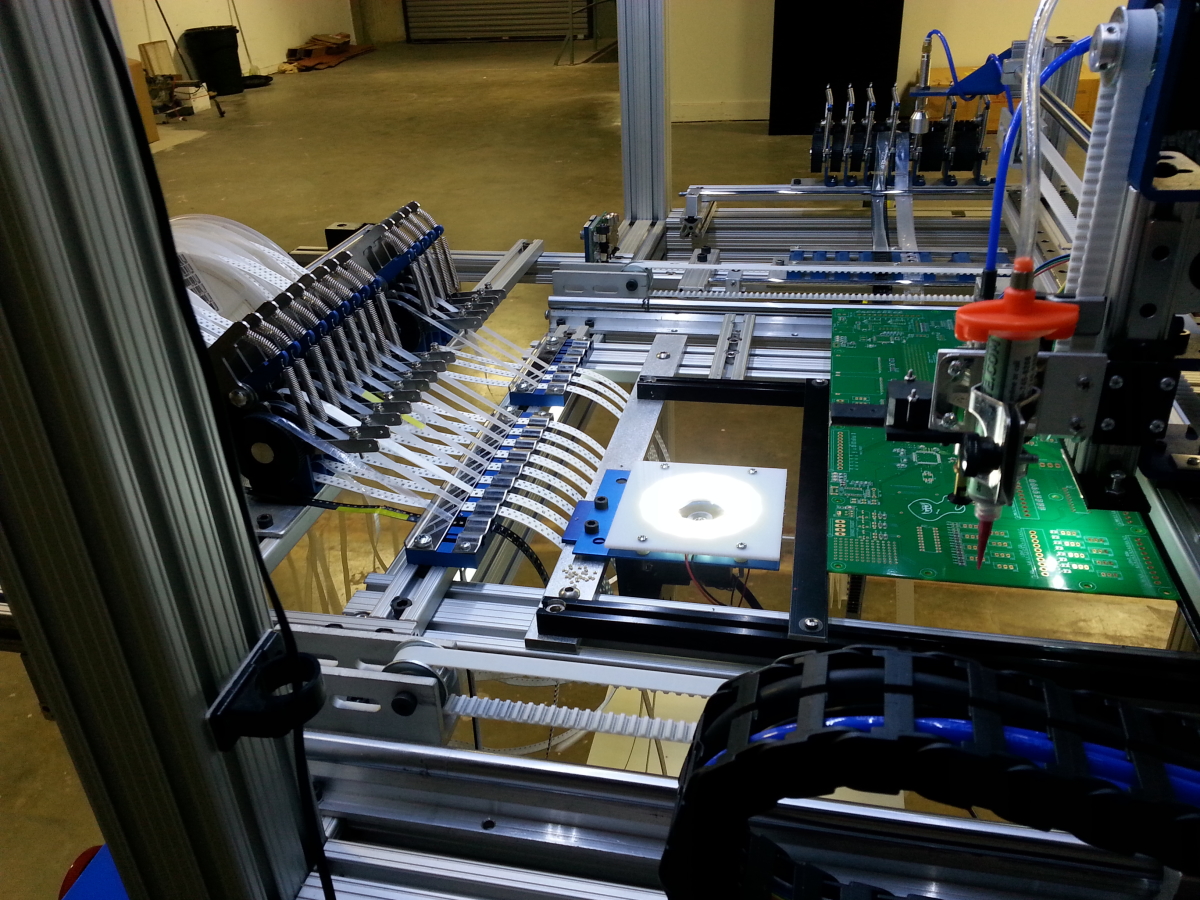
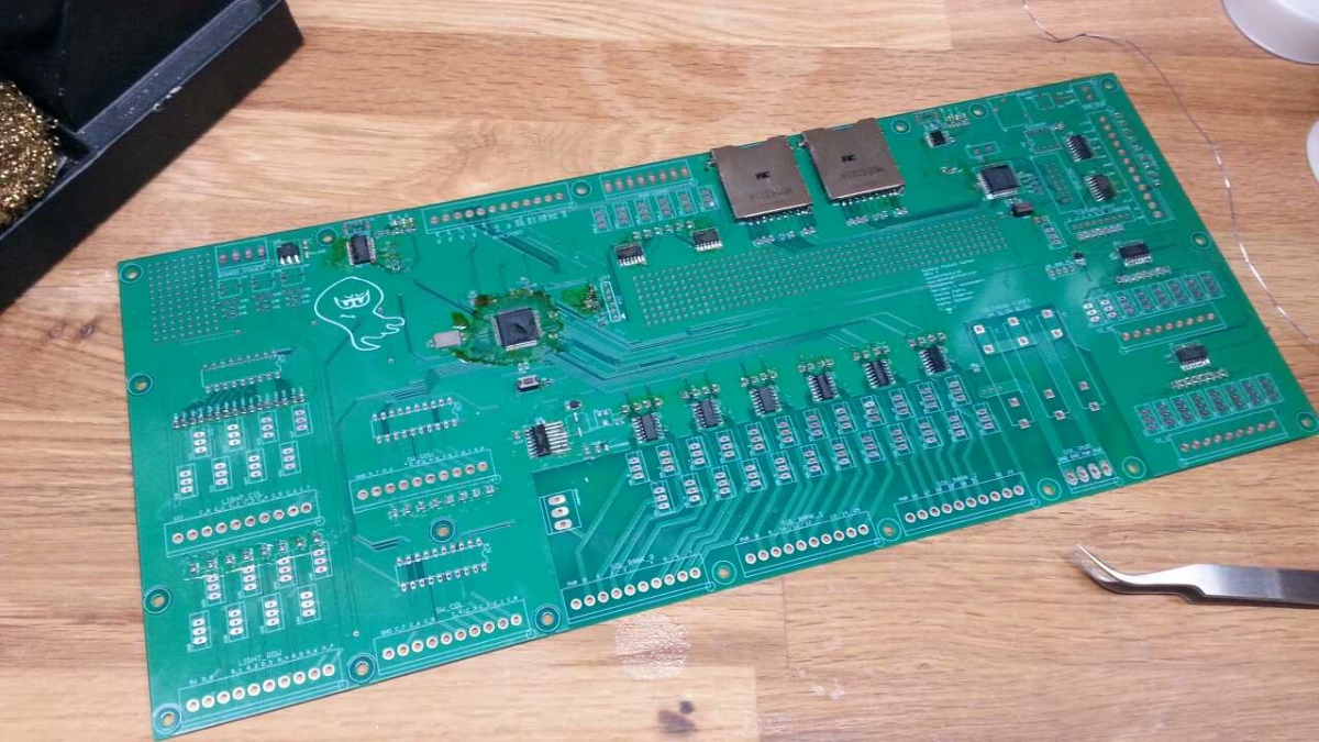
Pinheck board on the pick and place. Currently the machine is only setup to place the passive parts which are the resistors, capacitors, and LEDs. This consists almost 90% of the board parts.
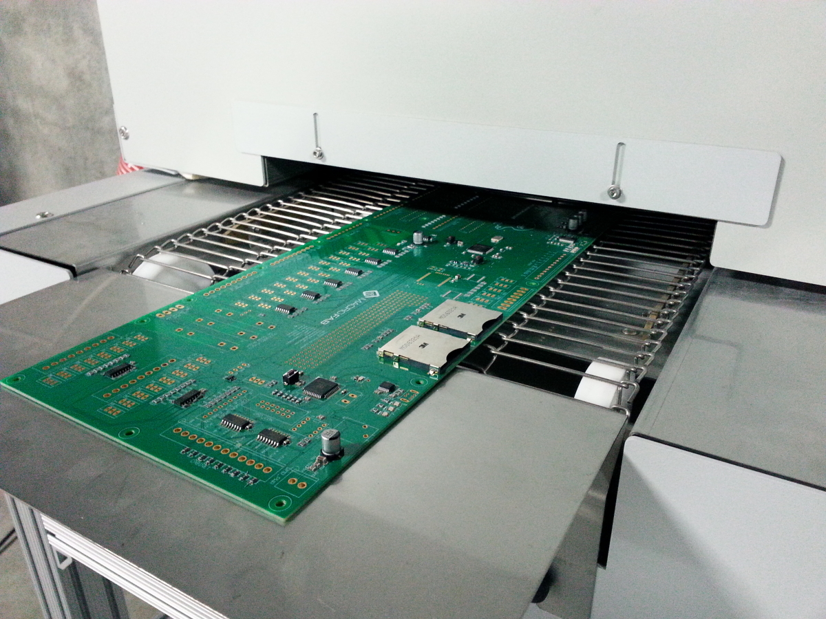
After the pick and place I manually placed the IC chips and placed it on the intake side of our reflow oven.
This is what the board looks like after coming out of the reflow. There are a couple bridges on the ICs so I will need to tweak my automatic paste dispenser settings.
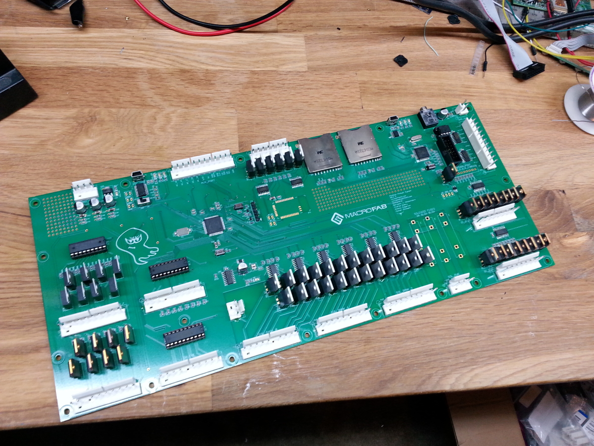
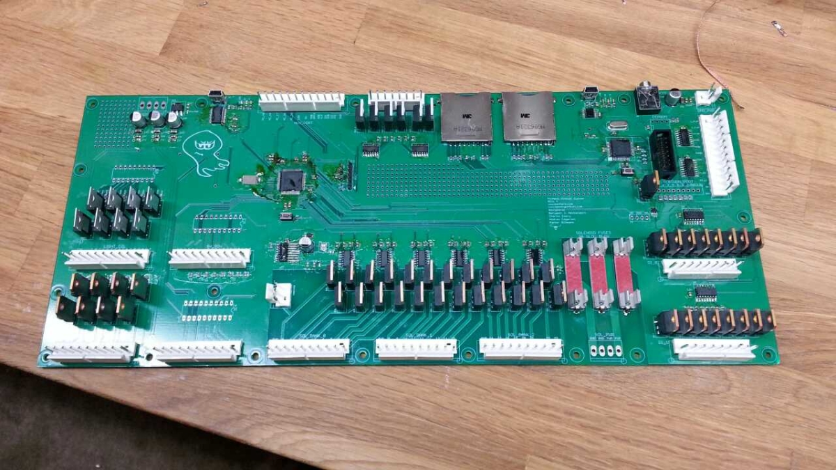
Finished soldering the through hole parts. Wishing I had a selective soldering machine about now!
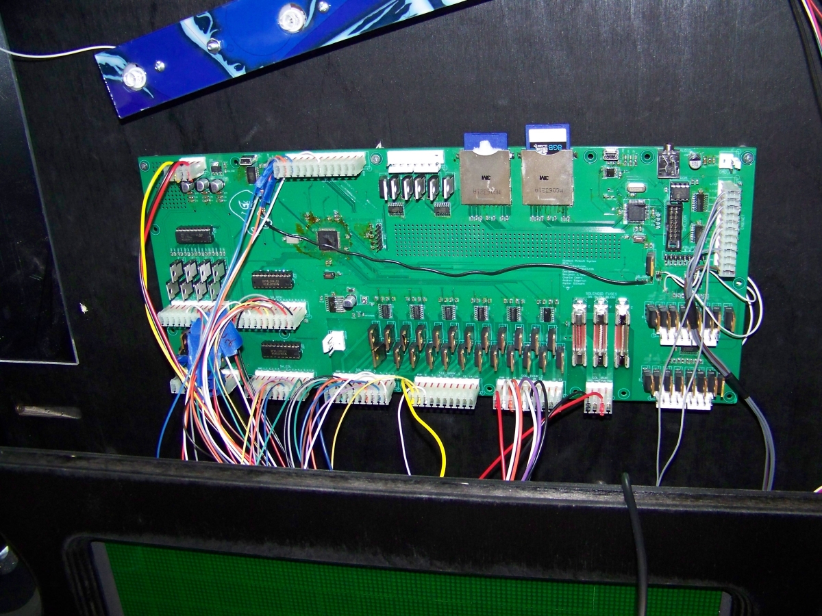
The Pinheck Pinball System is currently being tested in America’s Most Haunted. Once it gets a good bill of health we will move it to getting actual production boards made.
Just finished testing the REV 4 prototype. Flashed the Propeller and PIC32 successfully multiple times. Test software verifies that the hardware is working. I pushed the last fixes to GitHub that will make up the REV 5 board. Looking at selling the boards around the $400 mark fully assembled and ready to go with sample code.
Almost finished with the prototype. Just need to solder in some IC sockets when they come in and it will be done. Board only has one footprint fix but won’t prevent it from being tested.
This is the board I have been working on for Ben Heckendorn for his America’s Most Haunted pinball game. This is Revision 4. Will be finished soldering it tomorrow. Most of the passives are done as long with the ICs. Just the 0.1uF caps, mosfets, and connectors are left.
The verilog code is almost fully debugged. The demo code that will run on a Parallax Propeller is in the works. Right now the demo is fairly basic. Today I wrote a C program that takes a 4-bit bitmap image and strips out the header and and converts it to a 2-bit image. It then reorientates the data so the image is “correct”. Bitmap images data reads the image from bottom left to top right. This is essentially backwards. So the program corrects this which means less work for the microcontroller and faster transmission of pixels.
So I was still getting glitches on my inputs for Reset_Vector. I couldn’t figure out what was causing it because it would happen randomly and I couldn’t repeat the problem. The false inputs caused issues with ball triggering, score detection, and playfield actions. I figured it had to be glitches on the lines caused by EMF or something on the input driver. I knew it was the input driver cause when a solenoid fired randomly like the pop bumper it would register a hit which means that the microcontroller detected a hit.
To fix this issue I added a simple debouncer routine. Basically it makes sure a input is pressed for at least 2 Kernel cycles before saying that it was a hit. This keeps random spikes from registering as hits.
What it does is read in the inputs into a variable called new_inputs. The new_inputs then gets anded with a variable called old_inputs and the result is the inputs that where held for two kernel cycles. Then the new_inputs is copied into old_inputs for the next cycle to happen.
This system can be easily expanded to 3,4,ect cycles so the debouncer is extremely configurable in its sensitivity.