All posts by Parker

More Verilog Code

Sorry for the massive amount of code recently. To test to see if the RAM code works I wrote a program for the 16×96 display in RESET_VECTOR. If this works then I will order the PCB for the 32×128 DMD. If anyone has any suggestions please feel free to comment. This is the first time I have tried interfacing RAM on an FPGA before.


module LED_Matrix_16x96
(
  clk,row,col,SDRAM_CS,SRAM_CS,LAT,INPUT,SCLK
);

input  wire    clk;
input  wire    LAT;
input  wire    INPUT;
input  wire    SCLK;

output  reg [0:15]  row;
output  reg [95:0]  col;
output  reg [0:0]   SDRAM_CS;
output  reg [0:0]   SRAM_CS;

    reg [24:0]  clk_slow;
    reg [4:0]  row_cnt;
    reg [1535:0]  col_buffer;
    
    reg  [3:0]  read_addr;
    reg  [3:0]  write_addr;
    reg  [95:0]  disp_mem_data;
    reg      disp_mem_wren;
    wire  [95:0]  disp_mem_q;
    
    reg [3:0]  sel;

initial 
  begin
    row <= 16'b0000000000000001;
    col <= 16'b0000000000000000;
    SDRAM_CS <= 1'b0;
    SRAM_CS <= 1'b0;
    clk_slow <= 16'b0000000000000000;
    row_cnt <= 5'b00000;
    write_addr <= 4'b0000;
    read_addr <= 4'b0000;
    disp_mem_wren <= 0;
    sel <= 4'b0000;
  end
  
always @(posedge clk) 
begin
  clk_slow <= clk_slow + 1'b1;
  
  if(!LAT & row_cnt == 5'b01111)
  begin
  case(sel)
    4'b0000:
    begin
      write_addr <= sel;
      disp_mem_wren <= 1'b1;
      disp_mem_data <= col_buffer[1535:1440];
      sel <= 4'b0001;
    end
    4'b0001:
    begin
      write_addr <= sel;
      disp_mem_wren <= 1'b1;
      disp_mem_data <= col_buffer[1439:1344];
      sel <= 4'b0010;
    end    
    4'b0010:
    begin
      write_addr <= sel;
      disp_mem_wren <= 1'b1;
      disp_mem_data <= col_buffer[1343:1248];
      sel <= 4'b0011;
    end    
    4'b0011:
    begin
      write_addr <= sel;
      disp_mem_wren <= 1'b1;
      disp_mem_data <= col_buffer[1247:1152];
      sel <= 4'b0100;
    end    
    4'b0100:
    begin
      write_addr <= sel;
      disp_mem_wren <= 1'b1;
      disp_mem_data <= col_buffer[1151:1056];
      sel <= 4'b0101;
    end    
    4'b0101:
    begin
      write_addr <= sel;
      disp_mem_wren <= 1'b1;
      disp_mem_data <= col_buffer[1055:960];
      sel <= 4'b0110;
    end
    4'b0110:
    begin
      write_addr <= sel;
      disp_mem_wren <= 1'b1;
      disp_mem_data <= col_buffer[959:864];
      sel <= 4'b0111;
    end
    4'b0111:
    begin
      write_addr <= sel;
      disp_mem_wren <= 1'b1;
      disp_mem_data <= col_buffer[863:768];
      sel <= 4'b1000;
    end
    4'b1000:
    begin
      write_addr <= sel;
      disp_mem_wren <= 1'b1;
      disp_mem_data <= col_buffer[767:672];
      sel <= 4'b1001;
    end
    4'b1001:
    begin
      write_addr <= sel;
      disp_mem_wren <= 1'b1;
      disp_mem_data <= col_buffer[671:576];
      sel <= 4'b1010;
    end    
    4'b1010:
    begin
      write_addr <= sel;
      disp_mem_wren <= 1'b1;
      disp_mem_data <= col_buffer[575:480];
      sel <= 4'b1011;
    end
    4'b1011:
    begin
      write_addr <= sel;
      disp_mem_wren <= 1'b1;
      disp_mem_data <= col_buffer[479:384];
      sel <= 4'b1100;
    end
    4'b1100:
    begin
      write_addr <= sel;
      disp_mem_wren <= 1'b1;
      disp_mem_data <= col_buffer[383:288];
      sel <= 4'b1101;
    end
    4'b1101:
    begin
      write_addr <= sel;
      disp_mem_wren <= 1'b1;
      disp_mem_data <= col_buffer[287:192];
      sel <= 4'b1110;
    end
    4'b1110:
    begin
      write_addr <= sel;
      disp_mem_wren <= 1'b1;
      disp_mem_data <= col_buffer[191:96];
      sel <= 4'b1111;
    end
    4'b1111:
    begin
      write_addr <= sel;
      disp_mem_wren <= 1'b1;
      disp_mem_data <= col_buffer[95:0];
      sel <= 4'b0000;
    end
    default: 
    begin
      sel <= 4'b0000;
      write_addr <= 4'b0000;
      disp_mem_wren <= 1'b0;
    end
  endcase
  end
  else
  begin
    disp_mem_wren <= 1'b0;
    sel <= 4'b0000;
  end
end

always @(posedge clk_slow[10]) 
begin
  if(row_cnt > 5'b01111)
  begin
    row_cnt <= 5'b00000;
  end
  col <= disp_mem_q;  
  row_cnt <= row_cnt + 1'b1;
  row <= {row[15],row[0:14]};
  read_addr <= read_addr + 1'b1;
  
end
  
always @(posedge SCLK)
begin
  if(LAT)
  begin
    col_buffer <= {col_buffer[1534:0],INPUT};
  end
end

display_ram disp_mem_inst (
        .rdaddress (read_addr),
        .wraddress (write_addr),
        .clock  (clk),
        .data   (disp_mem_data),
        .wren   (disp_mem_wren),
        .q      (disp_mem_q)
);

endmodule

Updated Code for the 128×32 DMD

The old program took to make Logic elements to fit. Now it uses a 2-port RAM element to replace the huge registers. The protocol for shifting in is a bit different now. Instead of shifting in all the data at once and then Latching the user shifts in the data 64 bits at a time then latches.


module LED_Matrix_32x128
(
clk,e_cnt,row_cnt,col,SDRAM_CS,SRAM_CS,LAT,INPUT,SCLK
);

input  wire  clk;
input  wire  LAT;
input  wire  [7:0]  INPUT;
input  wire  SCLK;

output  reg [63:0]  col;
output  reg [0:0]   SDRAM_CS;
output  reg [0:0]   SRAM_CS;
output  reg [5:0]  row_cnt;
output  reg [4:0]  e_cnt;

reg [24:0]  clk_slow;
reg [63:0]  col_buffer;

    reg  [5:0]  read_addr;
reg  [5:0]  write_addr;
reg  [63:0]  disp_mem_data;
reg      disp_mem_wren;
wire  [63:0]  disp_mem_q;
initial
begin
SDRAM_CS &lt;= 1'b0;
    SRAM_CS &lt;= 1'b0;
    clk_slow &lt;= 16'b0000000000000000;
    row_cnt &lt;= 5'b00000;
    e_cnt &lt;= 4'b1000;
    write_addr &lt;= 5'b00000;
    disp_mem_wren &lt;= 0;
  end

always @(posedge clk) 
begin
  clk_slow &lt;= clk_slow + 1'b1;
end

always @(posedge clk_slow[10]) 
begin
  if(row_cnt &gt; 5'b01111)
begin
row_cnt &lt;= 5'b00000;
    e_cnt &lt;= {e_cnt[2:0],e_cnt[3]};
  end

  col &lt;= disp_mem_q;  
  row_cnt &lt;= row_cnt + 1'b1;
  read_addr &lt;= read_addr + 1'b1;

end

always @(posedge SCLK)
begin
  if(LAT)
  begin
    col_buffer &lt;= {col_buffer[62:0],INPUT[0]};
  end
  else
  begin
    disp_mem_data &lt;= col_buffer;
    disp_mem_wren &lt;= 1;
    disp_mem_wren &lt;= 0;
    write_addr &lt;= write_addr + 1'b1;
  end
end

display_memory disp_mem_inst (
        .rdaddress (read_addr),
        .wraddress (write_addr),
        .clock  (clk),
        .data   (disp_mem_data),
        .wren   (disp_mem_wren),
        .q      (disp_mem_q)
);

endmodule
128×32 DMD Verilog Code

Here is some Verilog code for a 32×128 DMD I am designing.


module LED_Matrix_32x128
(
clk,e_cnt,row_cnt,col,SDRAM_CS,SRAM_CS,LAT,DATA,SCLK
);

input  wire    clk;
input  wire    LAT;
input  wire    DATA;
input  wire    SCLK;

output  reg [63:0]  col;
output  reg [0:0]   SDRAM_CS;
output  reg [0:0]   SRAM_CS;
output  reg [5:0]  row_cnt;
output  reg [4:0]  e_cnt;

reg [24:0]  clk_slow;
reg [4096:0]  col_buffer;
reg [63:0]  col_temp [63:0];

initial
begin
col &lt;= 16'b0000000000000000;
    SDRAM_CS &lt;= 1'b0;
    SRAM_CS &lt;= 1'b0;
    clk_slow &lt;= 16'b0000000000000000;
    row_cnt &lt;= 5'b00000;
    e_cnt &lt;= 4'b1000;
  end

always @(posedge clk) clk_slow=clk_slow + 1'b1;  

always @(posedge clk_slow[10]) 
begin
  if(row_cnt &gt; 5'b01111)
begin
row_cnt &lt;= 5'b00000;
    e_cnt &lt;= {row[2:0],row[3]};
  end
  col &lt;= col_temp[row_cnt];  
  row_cnt &lt;= row_cnt + 1'b1;
end

always @(posedge SCLK)
begin
  if(LAT)
  begin
    col_buffer &lt;= {col_buffer[4094:0],DATA[0]};
  end
  else
  begin
    col_temp [0] &lt;= col_buffer [4095:4032];
    col_temp [1] &lt;= col_buffer [4031:3968];
    col_temp [2] &lt;= col_buffer [3967:3904];
    col_temp [3] &lt;= col_buffer [3903:3840];
    col_temp [4] &lt;= col_buffer [3839:3776];
    col_temp [5] &lt;= col_buffer [3775:3712];
    col_temp [6] &lt;= col_buffer [3711:3648];
    col_temp [7] &lt;= col_buffer [3647:3584];
    col_temp [8] &lt;= col_buffer [3583:3520];
    col_temp [9] &lt;= col_buffer [3519:3456];
    col_temp [10] &lt;= col_buffer [3455:3392];
    col_temp [11] &lt;= col_buffer [3391:3328];
    col_temp [12] &lt;= col_buffer [3327:3264];
    col_temp [13] &lt;= col_buffer [3263:3200];
    col_temp [14] &lt;= col_buffer [3199:3136];
    col_temp [15] &lt;= col_buffer [3135:3072];
    col_temp [16] &lt;= col_buffer [3071:3008];
    col_temp [17] &lt;= col_buffer [3007:2944];
    col_temp [18] &lt;= col_buffer [2943:2880];
    col_temp [19] &lt;= col_buffer [2879:2816];
    col_temp [20] &lt;= col_buffer [2815:2752];
    col_temp [21] &lt;= col_buffer [2751:2688];
    col_temp [22] &lt;= col_buffer [2687:2624];
    col_temp [23] &lt;= col_buffer [2623:2560];
    col_temp [24] &lt;= col_buffer [2559:2496];
    col_temp [25] &lt;= col_buffer [2495:2432];
    col_temp [26] &lt;= col_buffer [2431:2368];
    col_temp [27] &lt;= col_buffer [2367:2304];
    col_temp [28] &lt;= col_buffer [2303:2240];
    col_temp [29] &lt;= col_buffer [2239:2176];
    col_temp [30] &lt;= col_buffer [2175:2112];
    col_temp [31] &lt;= col_buffer [2111:2048];
    col_temp [32] &lt;= col_buffer [2047:1984];
    col_temp [33] &lt;= col_buffer [1983:1920];
    col_temp [34] &lt;= col_buffer [1919:1856];
    col_temp [35] &lt;= col_buffer [1855:1792];
    col_temp [36] &lt;= col_buffer [1791:1728];
    col_temp [37] &lt;= col_buffer [1727:1664];
    col_temp [38] &lt;= col_buffer [1663:1600];
    col_temp [39] &lt;= col_buffer [1599:1536];
    col_temp [40] &lt;= col_buffer [1535:1472];
    col_temp [41] &lt;= col_buffer [1471:1408];
    col_temp [42] &lt;= col_buffer [1407:1344];
    col_temp [43] &lt;= col_buffer [1343:1280];
    col_temp [44] &lt;= col_buffer [1279:1216];
    col_temp [45] &lt;= col_buffer [1215:1152];
    col_temp [46] &lt;= col_buffer [1151:1088];
    col_temp [47] &lt;= col_buffer [1087:1024];
    col_temp [48] &lt;= col_buffer [1023:960];
    col_temp [49] &lt;= col_buffer [959:896];
    col_temp [50] &lt;= col_buffer [895:832];
    col_temp [51] &lt;= col_buffer [831:768];
    col_temp [52] &lt;= col_buffer [767:704];
    col_temp [53] &lt;= col_buffer [703:640];
    col_temp [54] &lt;= col_buffer [639:576];
    col_temp [55] &lt;= col_buffer [575:512];
    col_temp [56] &lt;= col_buffer [511:448];
    col_temp [57] &lt;= col_buffer [447:384];
    col_temp [58] &lt;= col_buffer [383:320];
    col_temp [59] &lt;= col_buffer [319:256];
    col_temp [60] &lt;= col_buffer [255:192];
    col_temp [61] &lt;= col_buffer [191:128];
    col_temp [62] &lt;= col_buffer [127:64];
    col_temp [63] &lt;= col_buffer [63:0];
  end
end
endmodule

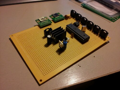
Reset Vector: New main board

image

A work in progress. Some of the new features include a socketable Propeller Chip, lockable headers, and separate power lines for the microcontroller and other sub systems. These changes will make the system easier to fix and prevent future problems.

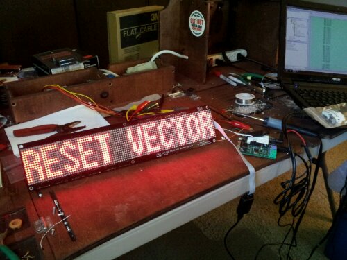
RESET VECTOR: DMD 16×96 Single Line Test

I finally finished building the Dot Matrix Display for Reset Vector. The Matrixing is run by a FPGA. The data is shifted in by the main propeller microcontroller. Currently the only code on the propeller is the single line text generator. I have a double line text generator and a animation driver that will load bitmaps off an SD card.

The Code will be up tomorrow.

WS2801 – 3 Channel PWM

The WS2801 is a 3-channel constant current LED drivers that is designed for controlling chains of RGB LEDs. The IC is controlled by a 2-wire serial control scheme that allows multiple WS2801 to be chained together. You can find the WS2801 in the link below. This demo code basically shifts out 24 bits (8bits per color) using a 2-wire protocol. This code only works for one WS2801. There is a object designed for multiple WS2801 already in the propeller OBEX. That design uses too many resources for use on my pinball machine so I wrote this to use as little resources as possible (no new cog).

The idea would be to have the WS2801 PWM a set of mosfets which would in turn be connected to the string of LEDs. This way you could light up a bunch of RGB LEDs without allot of CPU time taken from the Propeller. The Propeller only has to mess with the WS2801 when it needs to change the PWM signals.

Where to buy the WS2801.
Demo Driver

http://www.youtube.com/watch?v=EugcTOxVHx8

LDMD 16×16 Propeller Comm Test

Just finished the DMD (Dot Matrix Display) test for RESET_VECTOR. Since the Propeller is to slow to do the matrixing I am going to use a FPGA to do it. The propeller will send the data over a serial connection into a frame buffer on the FPGA. When all the data is on the FPGA the FPGA will update its matrixing buffer.

I have the Propeller to FPGA communication protocol written and tested as well. The Propeller loads the Data off the SD card and sends it serially to the FPGA.

http://www.youtube.com/watch?v=FGHIM8qgff8
http://www.youtube.com/watch?v=hrf3yXOP-KM

Propeller Code
FPGA Code
Block Diagram of the Dot Matrix.