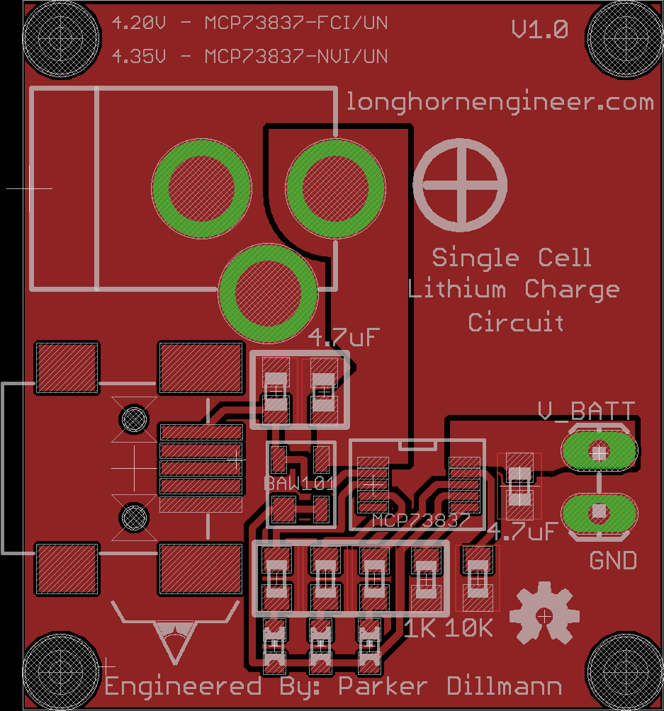
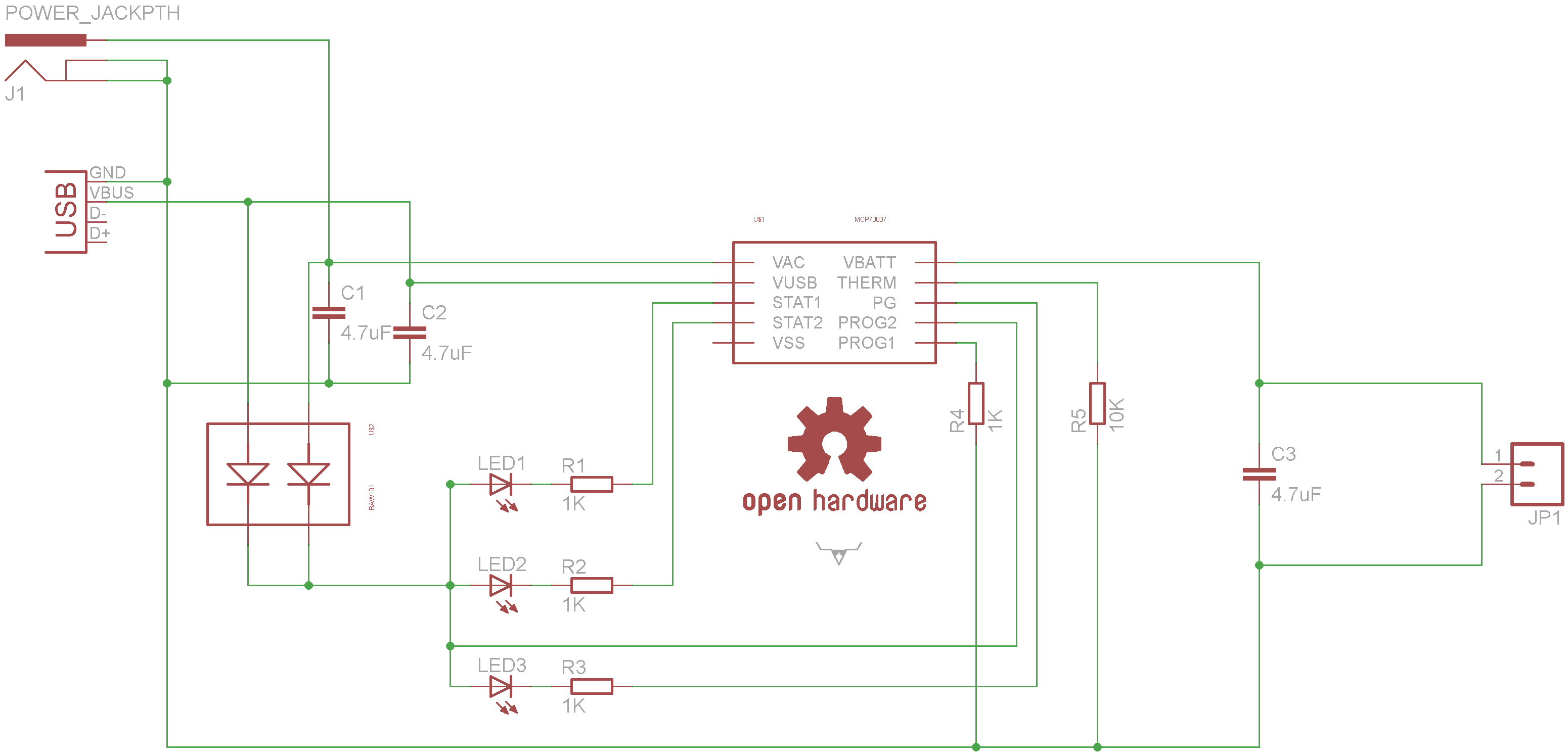
This circuit is designed around the MCP73837 chip. There are a couple different versions of this chip which allows the same PCB have a charge cut off voltage of 4.2V for normal lithium batteries and 4.35V for high capacity lithium batteries.
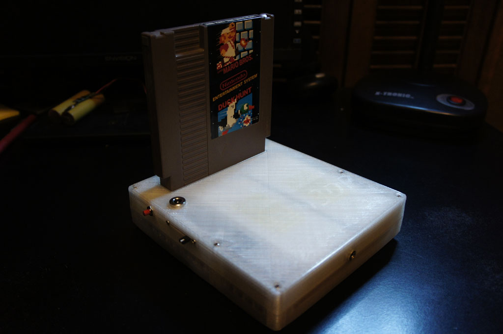
I always wanted to make a portable based of the famous Top Loader Nintendo. For one it is a 100% hardware compatible unlike NOACs (Nintendo On A Chip) and two it would make a whole bunch of Nintendo hardware collectors angry.
http://www.youtube.com/watch?v=abPyzVACP7I
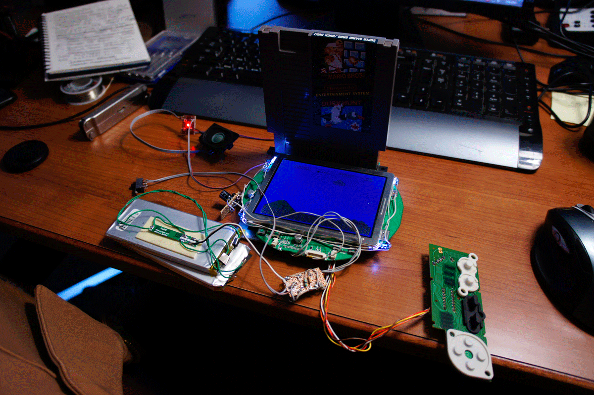
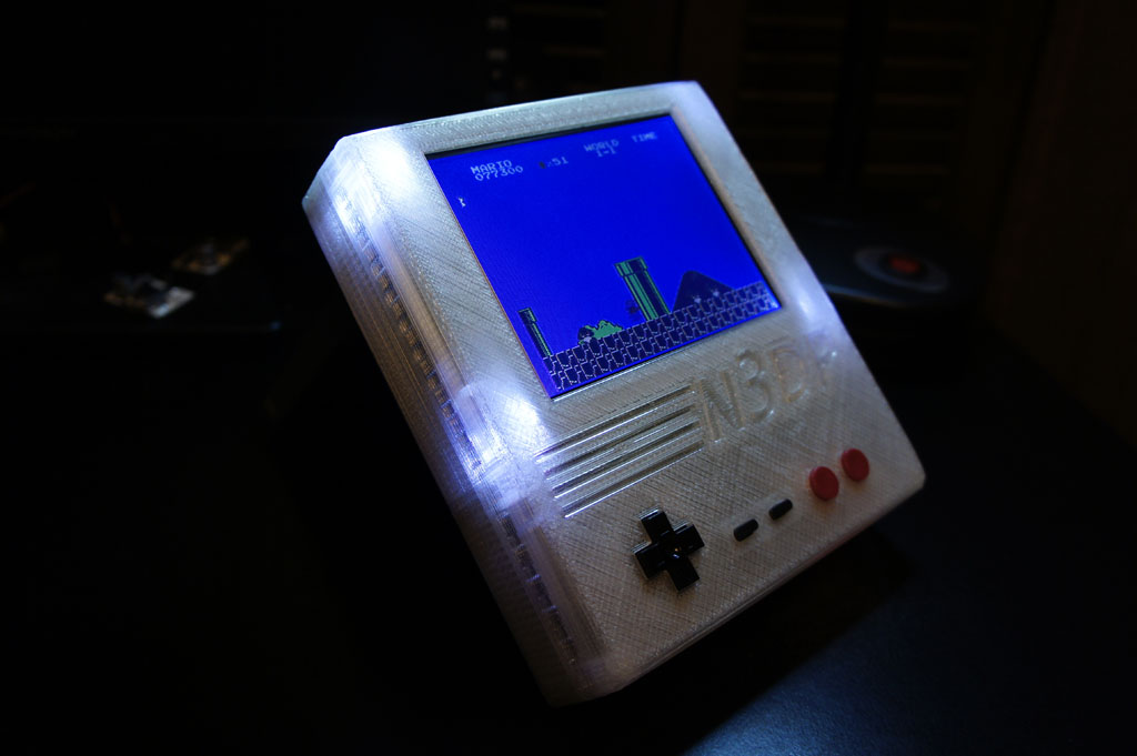
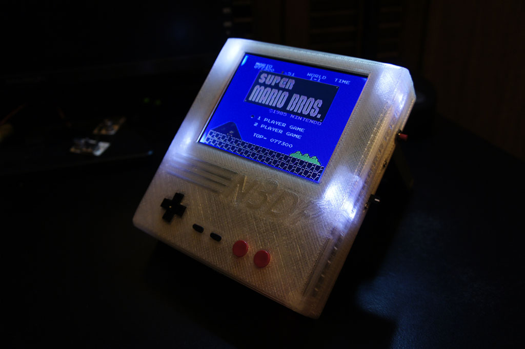
After a bunch of hacking and cutting of the board I got the electronics done. It has 5000mAh of 7.4V lithium power which will run the portable up to 10 hours. The 5″ PSone screen has been hacked to the bare minimum. I removed the 7805’s that power screen and ran the 5V rail off the switcher power supply I made to increase the efficiency. The PSone screen is LED modded as well.
When decided to use a separate sound amplifier as the PSone screen was to greedy on power and did not boost the volume enough. I am using a Sparkfun audio amp that uses the TPA2005D1. This is a very low power audio amp that reproduces sound very cleanly. It is a very efficient audio amp.
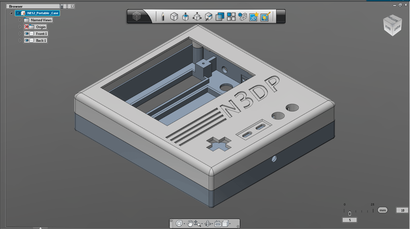
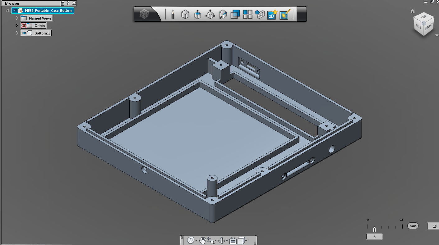
I designed the case in AutoDesk 123D which at the moment is free to download. The case will be 3D printed by my friend Chris Kraft.
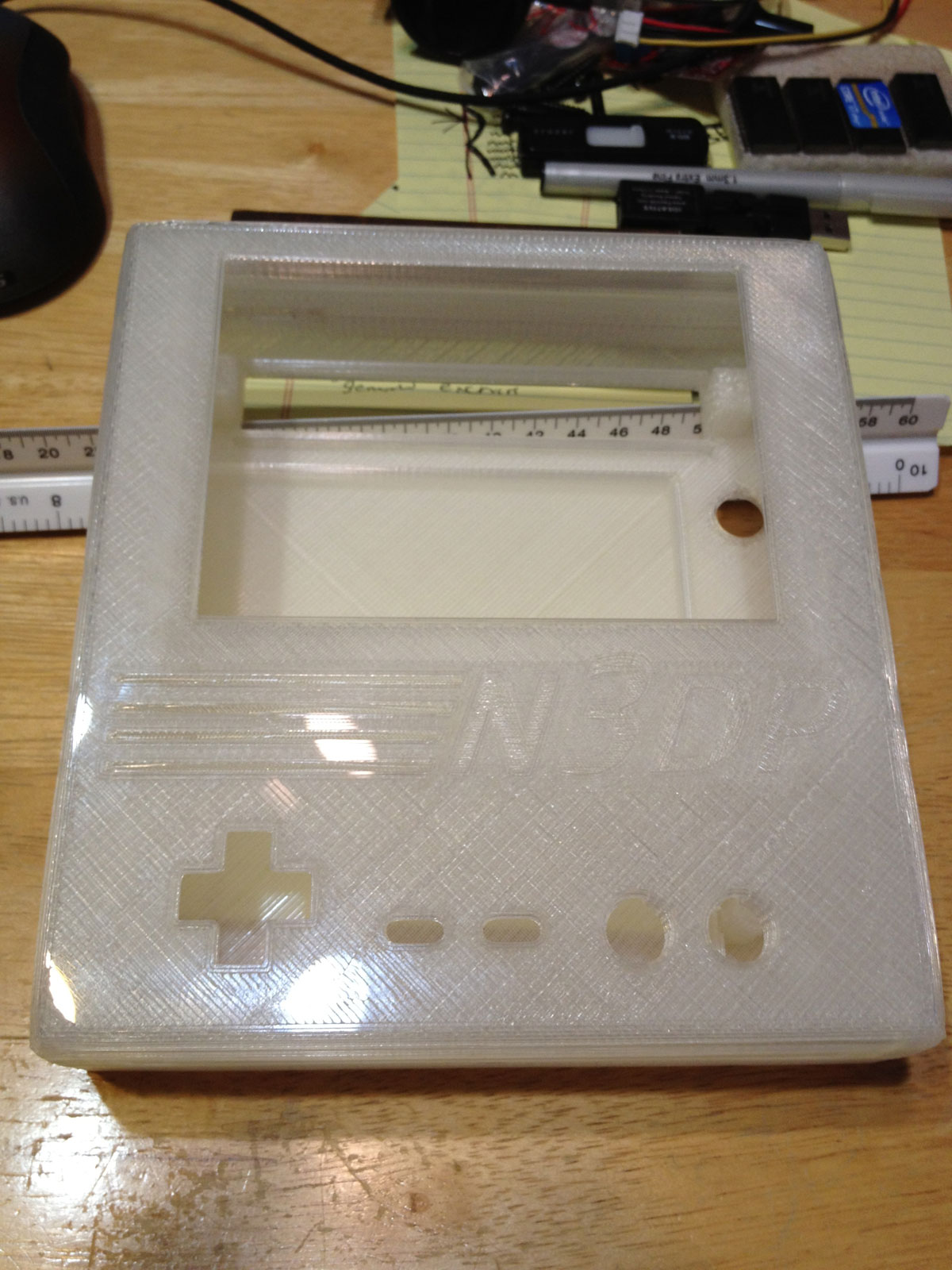
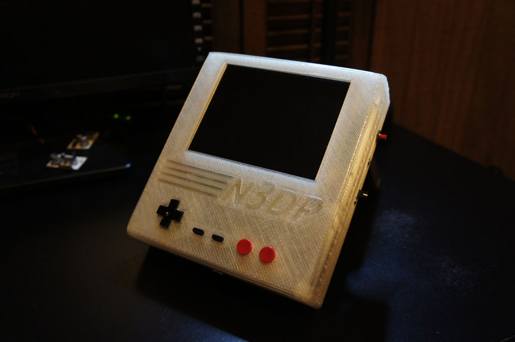
Here is the prototype case right out of the 3D printer.
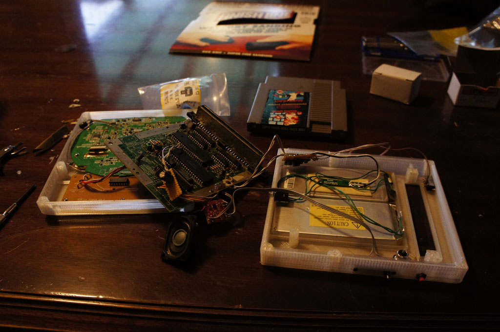
The prototype case with all the parts inside. I had to make some slight tweaks to the design. The updated 3D files can be downloaded below.
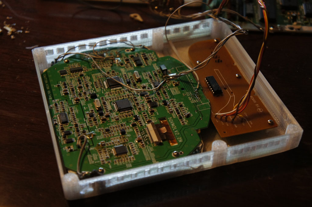
Assembling the front half of the case. Using size M2 sheet metal screws to attach the PCBs to the case. Holes are tapped with a 1.5mm drill bit before hand. for those that know the PSone screen accepts 7.4V then converts it down to 5V in some areas with a 7805 linear regulator. I removed the 7805s and attached my 5V switching power supply to the pads which dropped the power draw of the screen.
The back side houses much more parts. There is no hotglue in this portable. Everything is mechanically held in place. Some electrical tape is used to insulate parts but that is about it.
The button on the right is supposed to be for an internal MCU (like a MSP430) if I ever want to add more functionality to the portable.
I have some extra space between the front pcb boards and the rear pcb boards inside the case. I will be able to slim off about 1/8″ – 3/16″ off the thickness on the next case.
Like all portrait layout portables the top is a bit top heavy but it still has a good balance because of the thickness of the portable. The controls are laid out in the exact same dimensions as a real NES controller so it feels really nice. It has enough battery power to go for about 10 hours at max volume. I will need to tweak the audio amp a bit however as the volume is a bit soft. Should be able to adjust it by changing two resistors on the SparkFun amplifier board.
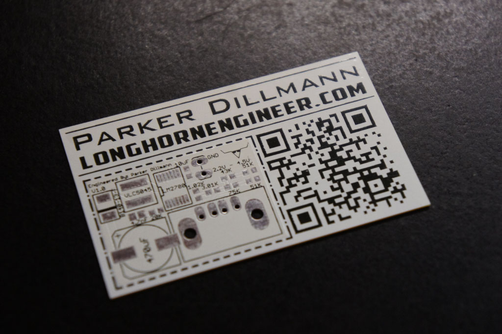
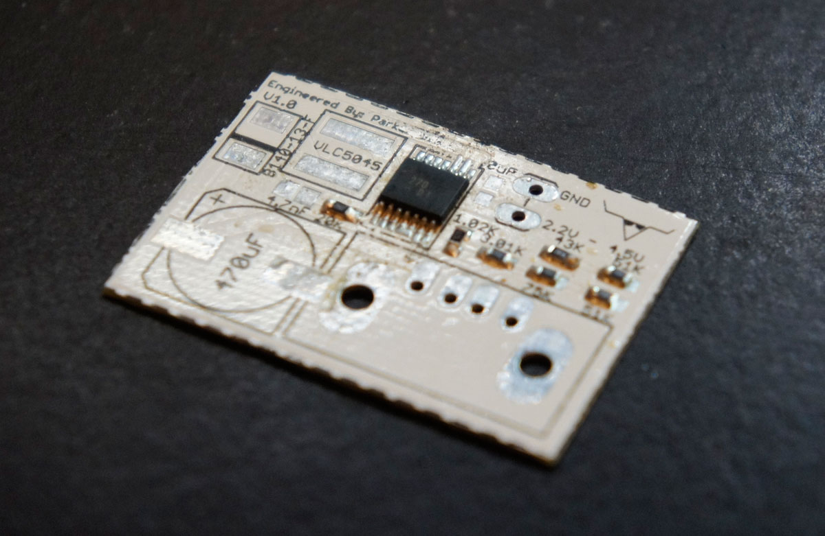
This is the how to page on how to build the SUPER BOOST pcb. Please refer to the disclaimer first. For hobby use only. This design is completely open source. Check the Super Boost project page for the file downloads.
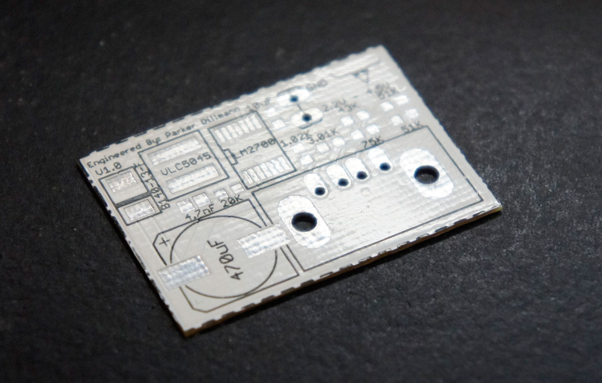
Since the board contains almost only SMD parts you should be familiar in soldering them. If not SparkFun has a really nice SMD soldering guide.
If you received the PCB on a business card you can cut the PCB out around the dotted lines or leave it as is.
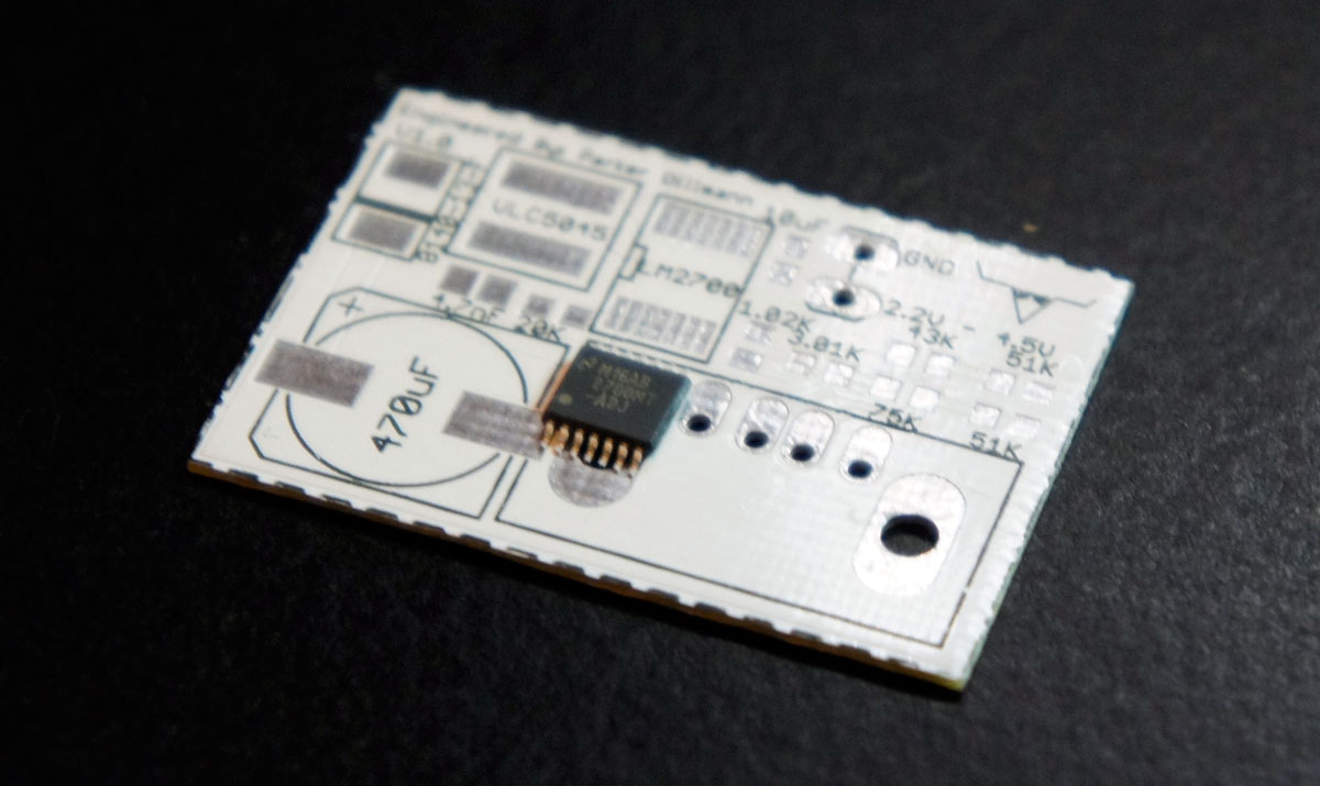
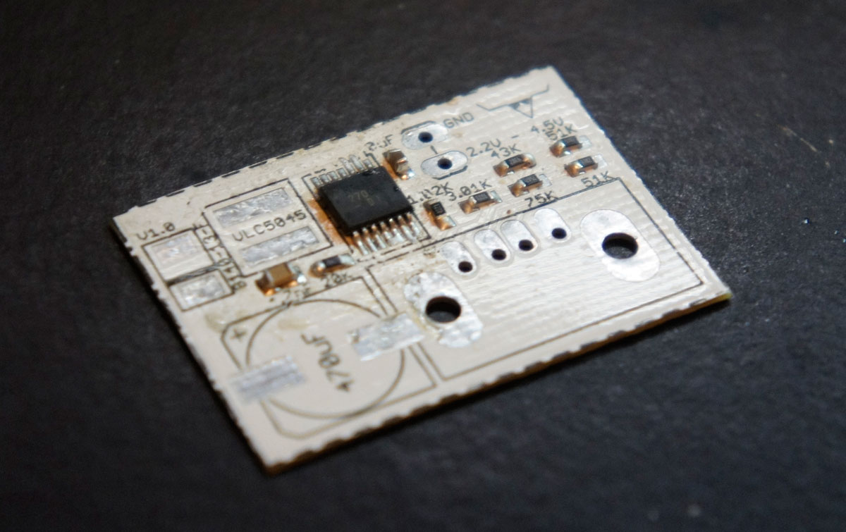
Start by tacking the LM2700 chip down with a soldering iron in a single corner.
I usually tack down the pin 1 on the chip then apply some flux then finish the chip. After soldering the LM2700 down solder the resistors down.
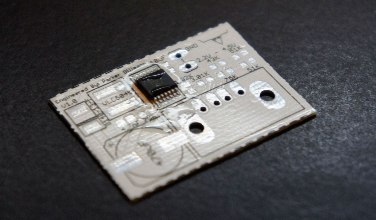
Then the two small SMD capacitors.
The inductor, diode, and large 470uF capacitor should be soldered next. The inductor is non polarized but care should be taken with the 470uF cap and diode to make sure they are originated correctly.
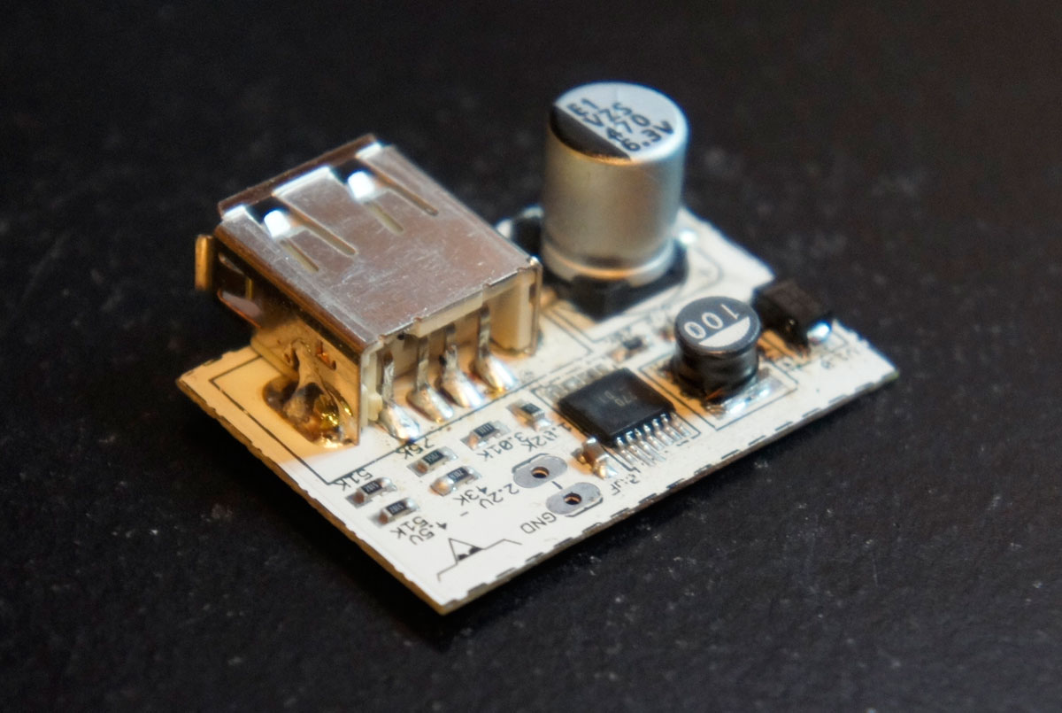
The USB port is the last thing to install. Before connecting your device to charge it use a multimeter and verify that 5V is across the 470uF capacitor terminals.
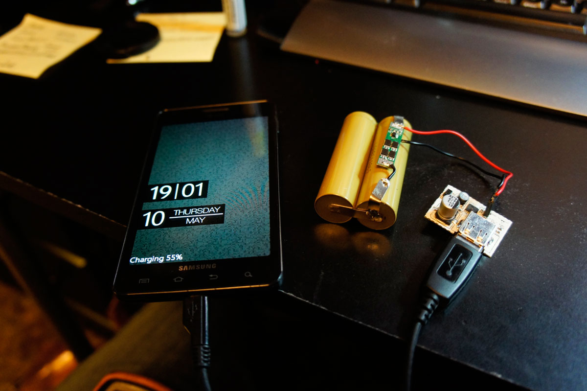
Success! Android phone charging. It is charging at a steady rate of 750mA.
This design is inspired by the Minty Boost but it fixes some of the issues in that design. The Minty Boost is limited to 600mA due to the LT1302 chip. The Super Boost uses the LM2700 which can push up to 3.6A. This will enable iPhones to charge much more quickly.
Charging more quickly will drain and reduce the life span of AA batteries so lithium batteries are the ideal source.
Chris Kraft just finished the top and bottom halves of the NES 2 (Top Loader) portable case. This is the prototype printed out of clear PLA (type of plastic). After I receive the case I will see if I need to do any tweaks to the design and then Chris will print it out of UV reactive purple PLA.
It turned out really nice. This is essentially the largest thing Chris can print on his 3D printer and it did a great job!
Finished the insides of the NES2 portable. Chris Kraft is going to 3D print the case.
I am using a Sparkfun audio amp that uses the TPA2005D1. This is a very low power audio amp that reproduces sound very cleanly. It is a very efficient audio amp.