
Automotive temperature sensors are typically thermistors. Resistance changes as the temperature changes. Most of the time you don’t want this to happen in normal resistors but thermistors are designed to change in a predictable manner so they can be used as sensors.
There are multiple ways to read the resistance of a thermistor but the easiest way is to make it part of a resistor voltage divider and use an ADC to convert the mid point to the temperature.
This is the circuit I designed for the Cyclone Pulse Wrangler.
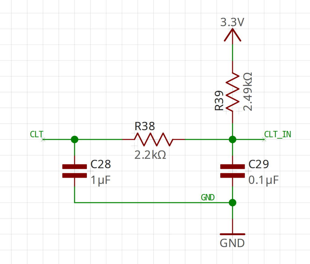
This is lifted from a variety of open source engine control hardware circuits.
I don’t know who or where the original 2.49K ohm pull up is from but most aftermarket sensors reference that pull up as well. I like AEM sensors and use the 30-2013 sensor in a lot of projects. They include easy to find calibration charts.
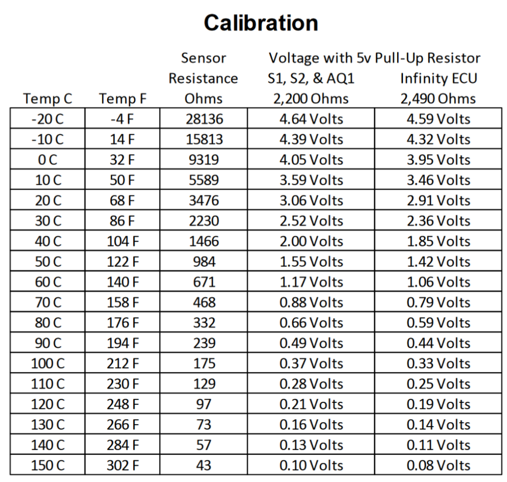
Now this is great if you are using a 5.0V sensor rail but the Cyclone Pulse Wrangler only has a 3.3V rail so some conversion is needed. I used chatGPT to convert the chart in the datasheet for the sensor into a CSV file I could import into a google doc.
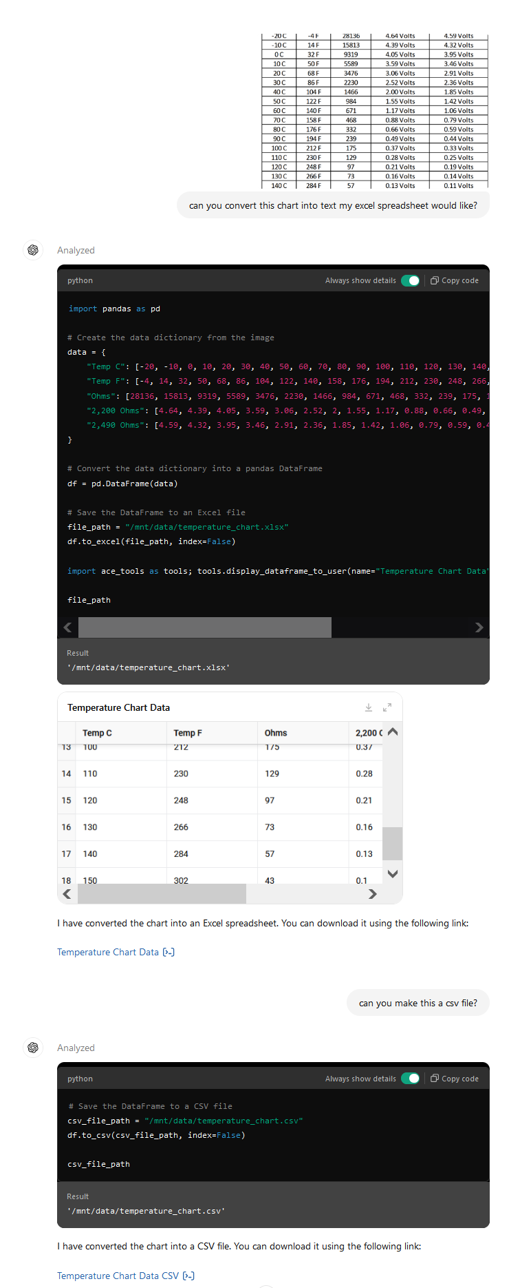
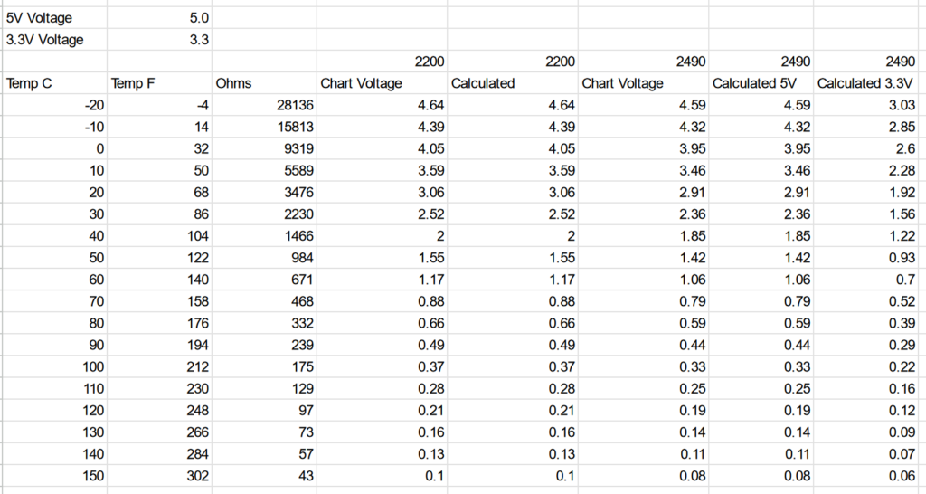
Then just used some ohms law magic to make the below chart. Here is a link to the google doc if you want to see the formulas and copy it for other sensors.
There are some downsides to this method. Since you are passing current through the thermistor there is some self heating involved which will of course change the resistance of the thermistor… and then change the current… and then change the resist…. yeah you see where this is going. Here is a good paper on measurement error in thermistors due to self heating by Ti.
A way around that is to control the voltage supply that goes into the voltage divider and only turn it on when you need a reading. Chips like the MAX6682 do this automatically. A high side fet could be incorporated into the design.
Is this a big problem in automotive applications? Engines run around the 100C mark so lets use that resistance from the chart above (175 ohms).
With the 2.49K resistor on the top side of the divider we get a voltage of 0.217V across our thermistor. That is ~0.00124A of current across it. We are talking 0.00026908 watts. Compared to the engine coolant. This is nothing.
Another source of error is current through the ADC. You want a high impedance here to prevent leakage current changing the reading. Most modern ADCs in MCUs are going to be high enough to prevent this being an issue in an automotive setting but it is always good to check if you are using a high end ADC that has low input impedance. An instrumentational opamp might be needed.