This is the evolution of the “jeep prop fan” controller I built what feels like a life time ago.
I did build this board as well back in 2016 but never finished the code or used it in the Jeep.
Here is the github repo of what I have so far. I did a complete redesign and rescope of the project. The original was more of a Power Control Module. Gonna try to stick to just a PWM fan controller this time around.
https://github.com/LonghornEngineer/Cyclone-Pulse-Wrangler
Biggest change was moving to a SAMD21 mcu. Have lots of these left over from my pinball controller days.
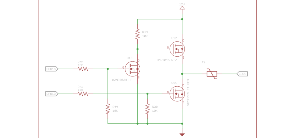
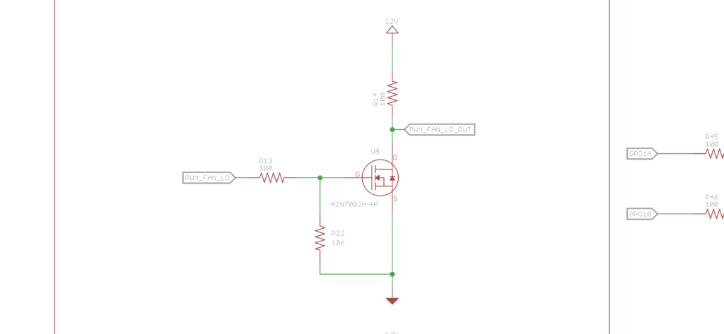
This is the PWM output circuit. Pulling the signal to 12V though a 100ohm 1/4W resistor. A2N7002H-HF n-channel fet pulls it down.
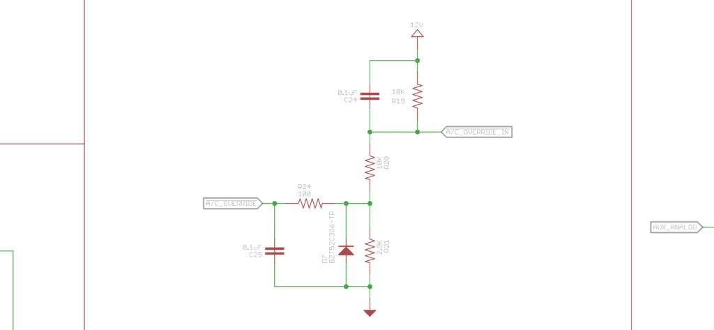
Here is the digital inputs to the system. These are active low inputs. 12V is the high. I am using a voltage divider to knock down what is the max voltage of ~14.7V to ~3.3V. I am not 100% sold on this circuit yet and might go with an optocoupler if convinced with the right part number. A 3.6V Zener Diode (BZT52C3V6-TP) helps make sure that I/O pin doesn’t get too out of wack.
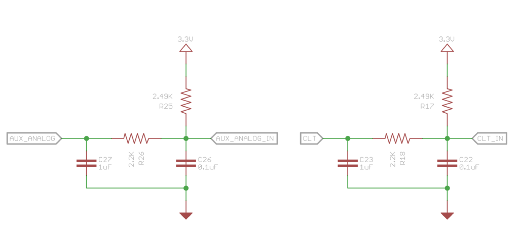
To read the temperature sensors, which are thermistors, I just lifted the circuit that other engine control uses. Low pass filter and a pullup. I/O pins are protected with a SP721ABG SCR/Diode chip.
The last part to highlight so far is the driver outputs. These can be used to drive relays or indicator lights or whatever. These can be a voltage source or a ground sink depending on what is needed. Basically a half bridge setup. Don’t set both I/O pins high ![]() Maybe I add in some gate logic to prevent shoot through condition? Or just write the code with a check before setting the outputs?
Maybe I add in some gate logic to prevent shoot through condition? Or just write the code with a check before setting the outputs?