
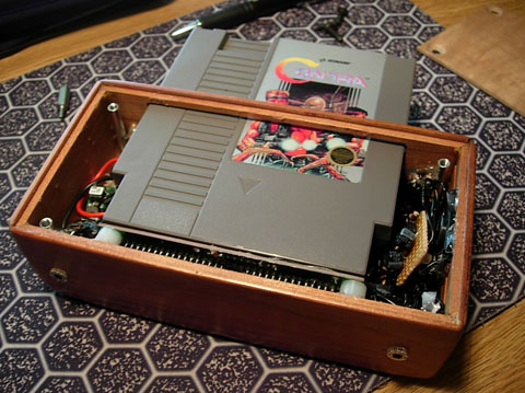
After the success of my first two portables decided to start shrinking the size of my portables to something that would be easier to carry around. For V3 of the NESp I am going to base it off a NOAC (Nintendo On A Chip) board. A NOAC is basically a chip that emulates how a real NES works. The advantages are that it reduces power consumptions of the portable and it makes it smaller. However NOAC’s are not 100% compatibly with every single game (about 3-5 games don’t work).
Design Goals
Make it as small as possible
Use a 3.5″ screen
Smaller footprint then the PSone 5″
Large enough to easily see whats going on
Pre-LED modded
Minimum of 5 hours of life
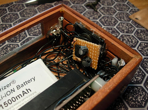
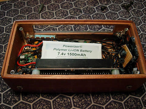
Lithium battery 1600mAh
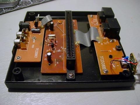
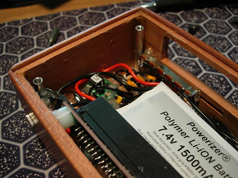
The NOAC is comprised of 3 boards. The board on the left is the A/V plugs and DC input. The middle board is where the NOAC is located and the right board is where the controllers are plugged in. The only board necessary is the middle board.
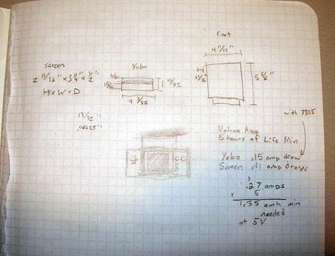
The total size should be around 6.5″x4″x2″ which is roughly half the size my previous portable (SNES V1) is.
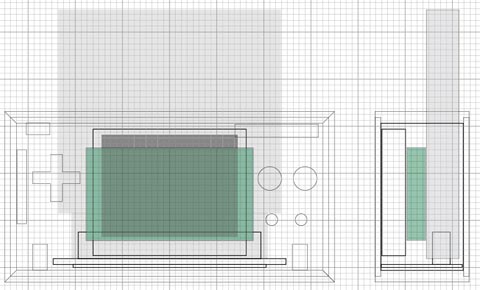
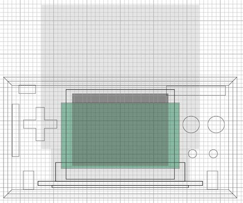
Finished the design today. Turned out pretty close to what I wanted it to be. 6.5″x3.5″x2″
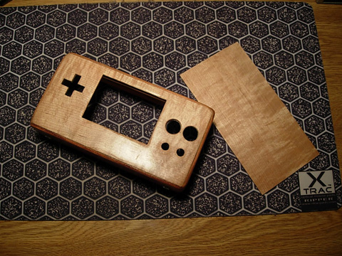
I finished the case. Turned out pretty good I think. Looks a lot like a wooden brick. The buttons and D-pad are done but I didn’t take a picture of those.
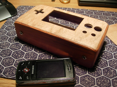
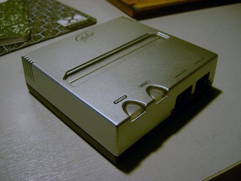
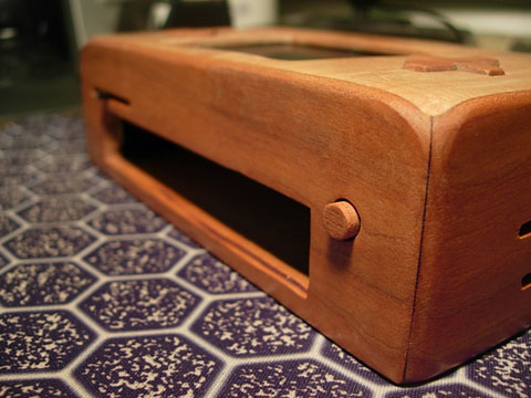
Here you can see the two input jacks. The one of the left will be headphones and the one on the right will be the recharge jack.
Finished hacking the NOAC and LCD screen today.
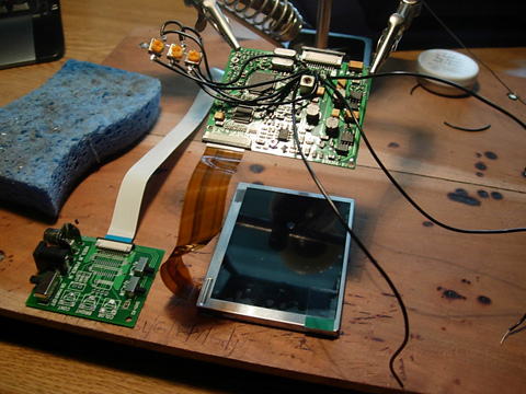
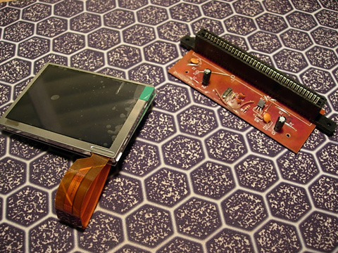
The controller board has to be removed so the screen will fit in the case. The board contains the inputs and other various controls for the LCD screen. These have to be soldered directly to the driver board for the screen. The board on the left is the controller board and the board in the clamps is the driver board.
The trim pots control the brightness, color, and contrast. Removing the control board reduced the overall thickness of the LCD screen from 1″ to 1/2″. The inputs and trim ports where connected directly to the driver board with 24AWG solid strand hook up wire. The driver board has convenient soldering pads for this.
To fix the LCD screen into the case I used some hotglue. After I install the controls and buttons I will fix the trim pots to the case.
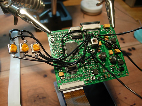
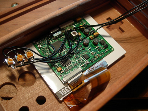
The NOAC was attached to the case with hotglue and soldered to the LCD screen. Slowly starting to get somewhere with this portable.
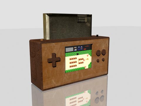
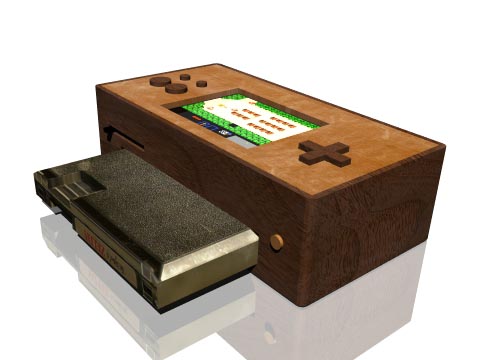
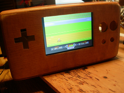
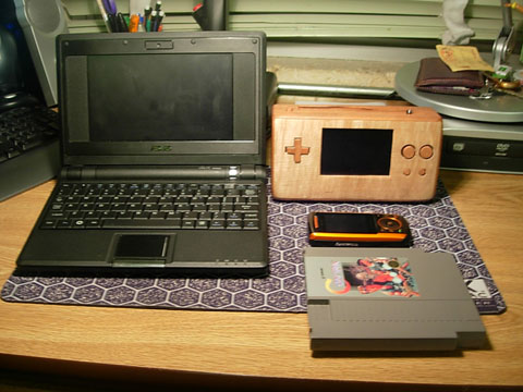
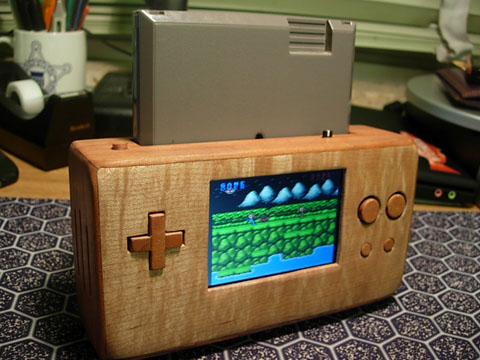
Back with good news. I finished the portable and I am now testing it.
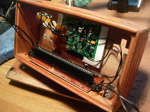
Well enough with the guts.
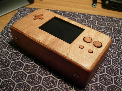
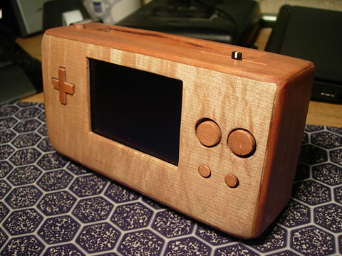
The case turned out much better then I had expected. At first I didn’t like how I rounded the corners but the more I play the portable the more I like them.
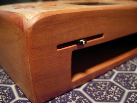
The power button here is epoxied to the top of a large tact switch.
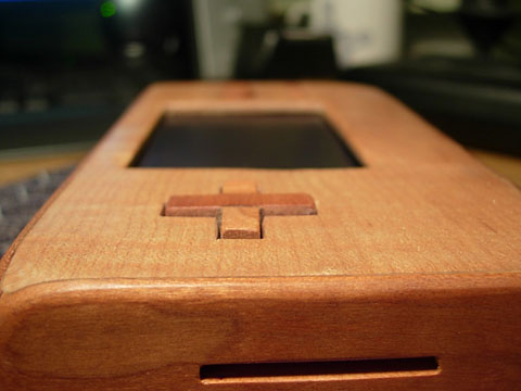
I received a suggestion to make the D-pad out of 1 solid piece of wood. I will look into it the next time I build a case.
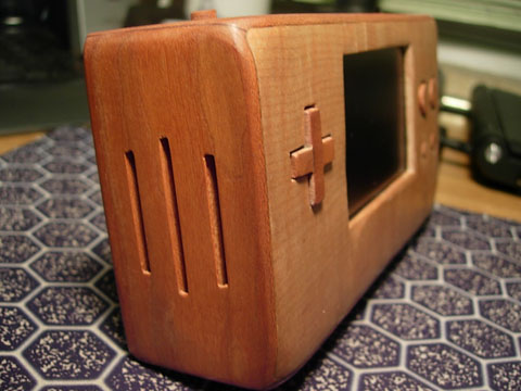
Since the portable is so small the controller boards took up all the space on the front panel so the speaker had to go here.
This volume slider is probably my favorite new feature of my design. Expect to see it in upcoming portables.
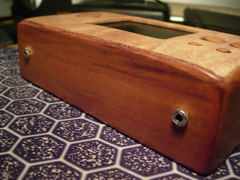
The one on the left is the headphone jack. It automatically switches the sound to the built in speaker off when you plug a headset in. The jack on the right is the charger. It also disconnects the battery from the main circuity when you charge the battery. The portable is unplayable when charging but it is safer when charging lithium batteries.
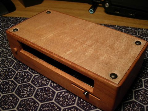
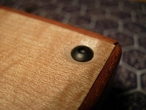
I really like these hex headed screws. They look much better then the normal stainless steel machine screws that I previously used.
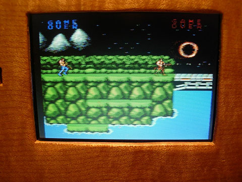
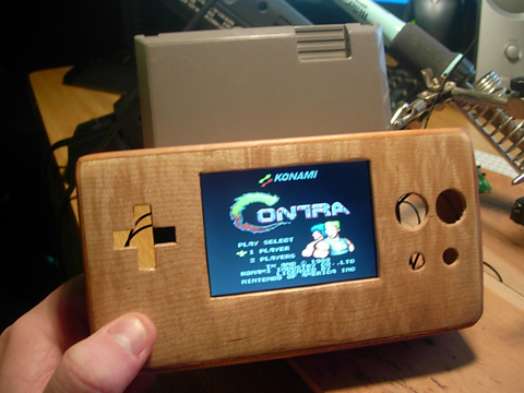
Being the first portable I built with an AEIComp LCD screen I was very impressed with the quality of the screens. They are bright, clear, and sharp.
I am slowly refining my portable designs. In my next portable I am going to make the guts of the portable as streamlined as possible. Even though no one sees the insides it is just nice not to have a nest of wires to deal with.