
Atari 7800 NTSC A/V Install Guide
Read through the instructions carefully before attempting. Also read the disclaimer.
This guide is for the install of the Longhorn Engineer Atari 7800 Video mod on NTSC machines.
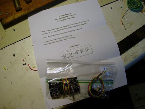
Your kit should contain the following.
1 – Atari 7800 A/V mod board
2 – RCA Jacks
1 – S-Video Jack
2 – Screws
1 – Printout
Tools Needed
Philips Screwdriver
Flat Head Screwdriver
Scissors
Tape
Drill bits
- 1/16″ Twist bit
- 1/8″ Twist bit
- 1/4″ Forstner Bit
- 1/2″ Forstner Bit
Electric Drill
9mm Wrench or Needle Nose Pliers
Soldering Iron and Solder
Desoldering iron or equivalent
Small clippers
Forstner Bits are preferred over regular twist bits because unlike twist bits they don’t “dig” into the brittle plastic which can cause the case to break. Harbor Freight sells a set of what you need for $10.
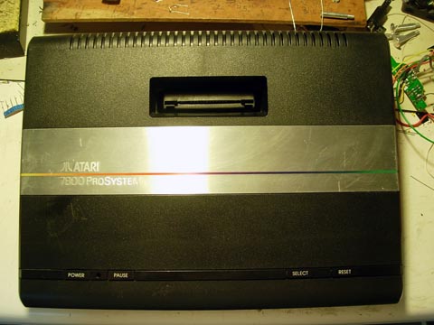
Find a clean area to start working on your Atari.
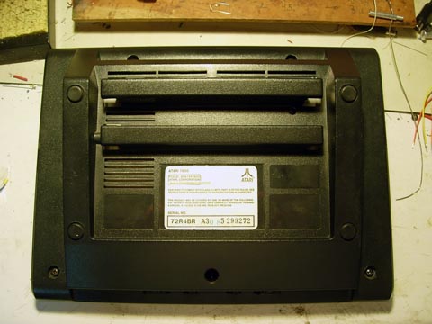
Flip it over and unscrew the 5 screws that hold the top on. Remove the top and place it somewhere where it won’t get scratched.
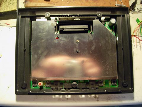
In the bottom half there is the circuit board covered with the RF shielding. Remove the PCB from the bottom half of the case. Place the bottom of the case and set it aside for later.
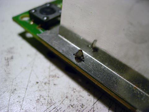
The RF shielding needs to be removed. It is held on by these twisted tabs. Remove them by using your pliers and twisting them straight.
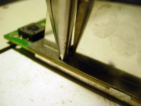
After all the tabs are straight slide a flat head screw driver between the PCB and the RF shielding. It is easier to do this on the bottom where there are slots in the RF shielding. Be careful and don’t use to much force as you are just “popping” the two parts of the RF shield apart.
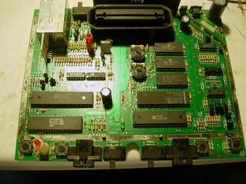
With the top and bottom part of the shielding removed its time to install the mod.
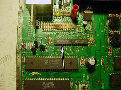
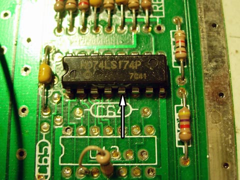
On the left side of the board there is a chip that will need to be removed for the mod to be installed correctly.
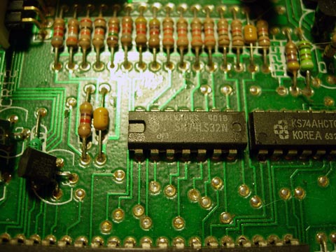
Close up of the chip. It reads SN74LS32N.
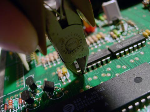
Take your clippers and cut the legs off the chip. Try to leave allot of leg on the PCB as it will be easier to remove later.
After removing the chip you should have something like above. Now to remove the legs. Heat the base of the leg with a soldering iron. When the solder is melted use pliers to remove the leg. Make sure the solder is melted and don’t force the leg out as you may ruin the PCB this way. The leg should just come straight out with almost zero force from the pliers.
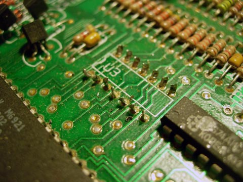
After removing all the legs you will have to remove the solder from the holes. When using the desoldering iron, heat the hole up for a good 2-3 seconds then release the suction. If you can’t get all the solder out add some more solder with the iron then try again. Don’t rub the desoldering iron on the PCB as it can tear into the traces.
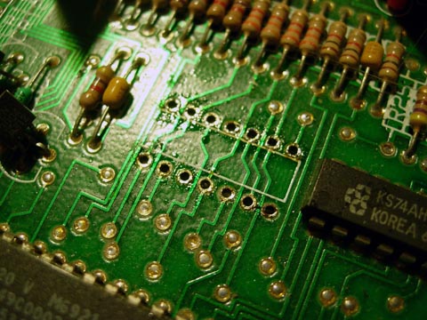
Clean holes and ready for the socket.
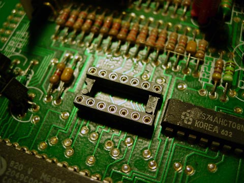
Place this part into the area and solder it in from the back side of the PCB. To make it easier you can try taping the part to the PCB to hold it in place.
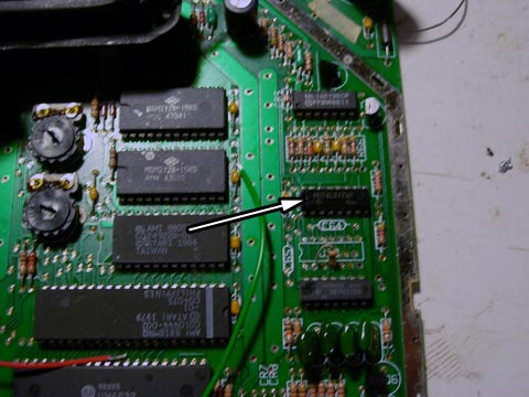
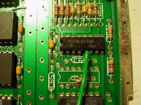
On the right side of the board theres this chip. Some 7800’s look a bit different in this area but this chip is the same for all revisions.
Solder the long green wire to the 5th pin on the chip as indicated in the picture.
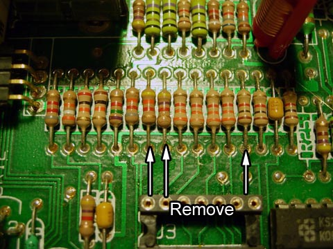
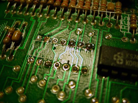
Now back at the left side of the board there is a row of resistors right above that socket that was just soldered in. Remove the resistors above.
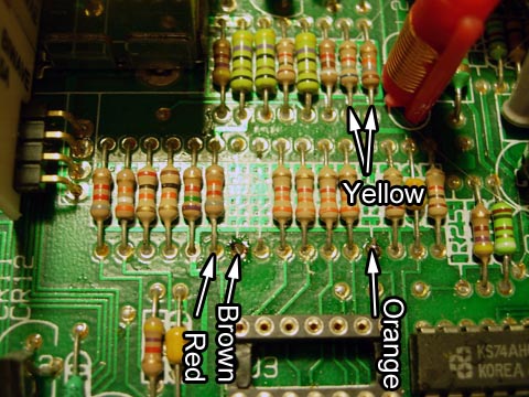
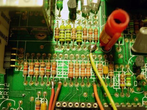
Solder the shorter Yellow, Red, Orange, Brown wires to the spots above. The Yellow bridges those two spots.
Pop the 7800 mod into the socket. It could take a bit of force to get it to snap in so just make sure you are lined up correctly.
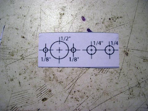
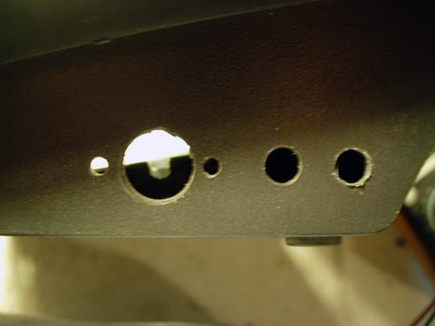
Cut out the drill diagram from the sheet that is supplied with the kit. Since the 7800 is mono sound only cut off the last spot.
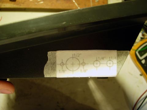
Tape the diagram on the right side of the 7800 bottom case like above.
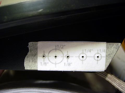
First start with the 1/16″ drill bit and make pilot holes. Then drill the 1/2″ and 1/4″ holes with the Forstner bits and then drill the 1/8″ screw holes for the S-video jack.
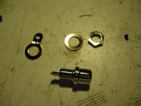
The RCA jacks have 4 parts; the jack, a washer, a wire tab, and a nut. Place the RCA jack in the 1/4″ hole and then the wire tab followed by the washer and nut. Tighten the nut with a wrench of pliers.
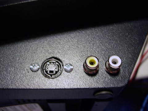
The S-video jack gets screwed in right beside the RCA jacks.
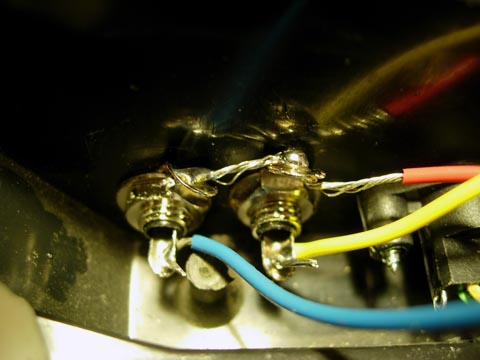
Solder the long yellow, blue, and red wires to the RCA jacks. The red one goes through both wire tabs.
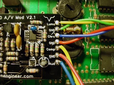
On the right side of the 7800 mod PCB solder the wires from the S-video jack to there spots as shown above.
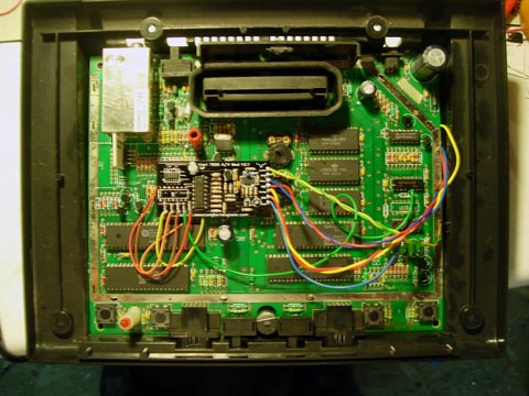
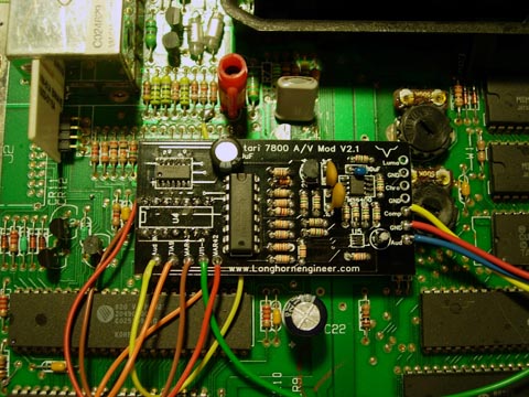
Here is an overview of the entire mod installation. All that is left is to put the top back on and screw it all together and play some 7800!