
Atari 2600 Sears Arcade II A/V Install Guide
Read through the instructions carefully before attempting. Also read the disclaimer.
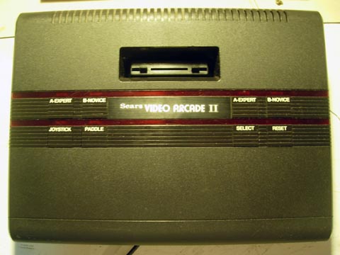
This guide is for the install of the Longhorn Engineer Atari 2600 Video mod for the Sears Arcade II.
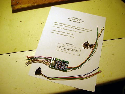
Your kit should contain the following.
1 – Atari 2600 A/V mod board
3 – RCA Jacks
1 – S-Video Jack
2 – Screws
1 – Printout
Tools Needed
Philips Screwdriver
Flat Head Screwdriver
Scissors
Tape
Drill bits
*1/16″ Twist bit
*1/8″ Twist bit
*1/4″ Forstner Bit
*1/2″ Forstner Bit
Electric Drill
9mm Wrench or Needle Nose Pliers
Soldering Iron and Solder
Small clippers
Forstner Bits are preferred over regular twist bits because unlike twist bits they don’t “dig” into the brittle plastic which can cause the case to break. Harbor Freight sells a set of what you need for $10.
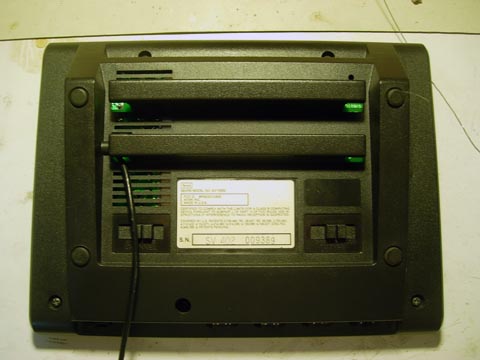
First we will start by flipping the console over and removing the five screws. Don’t use to much force on removing the screws as you can crack the screw posts with to much force. Ease them out with a steady motion.
Take the cover off. On the push switches there are some washers. Make sure to take those off so you don’t loose them later.
Remove the RF cable from its socket by pulling it straight out of its socket.
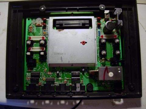
Pick the Atari mainboard out of the case. Remove the RF cable from the case by pulling it through the back.
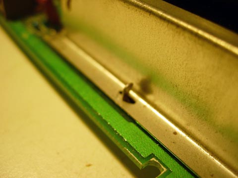
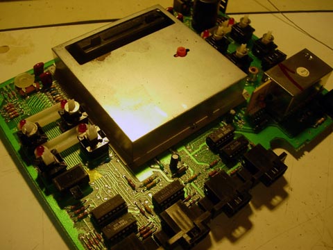
The Shielding around the Cartridge Slot area needs to be removed before we proceed. Using your pliers grab these tabs that are around the shielding and twist.

The top of the shielding should pop off.
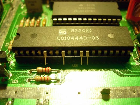
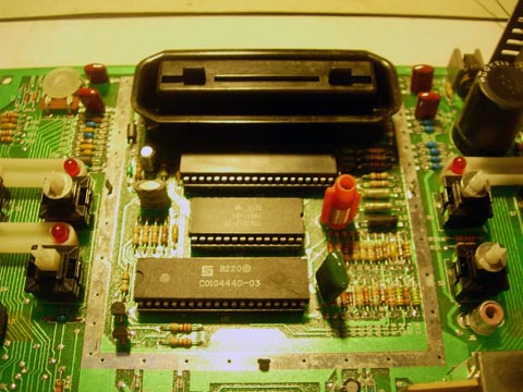
There are three chips under this shielding the most bottom one needs to be removed. Take a flat headed screw driver and pry one end a bit and then pry the other side. Do this till the entire chip comes out. Then bend the 6th, 9th, 12th, and 13th pin outwards. Replace the chip in its socket. It should look like the above when finished.
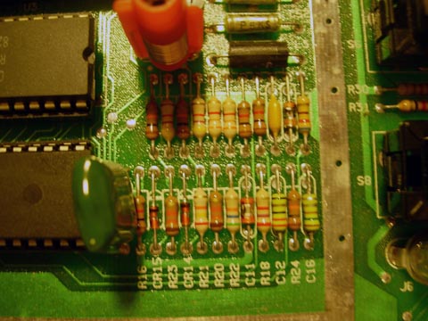
To the right of the TIA chip there are some resistors.
https://longhornengineer.com/images/howto/videomods/Atari2600/SearsVA2/DSCN4256.jpg
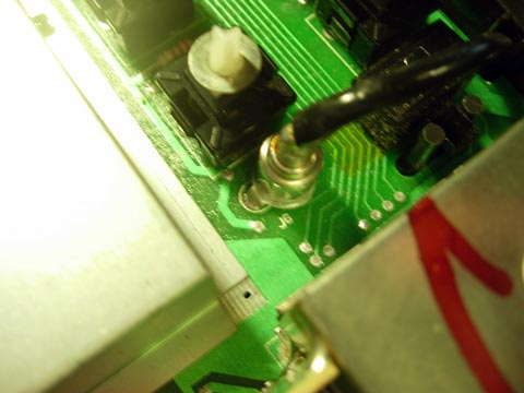
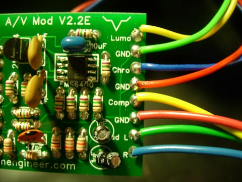
Six of the wires on the left side of the Video Mod Board need to be soldered to the spots as indicated above.
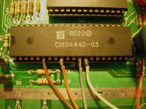
The last four are soldered to the bent pins on the TIA chip as shown. Do not pull on the wires that are soldered to the TIA. Doing so may cause a pin to break off.
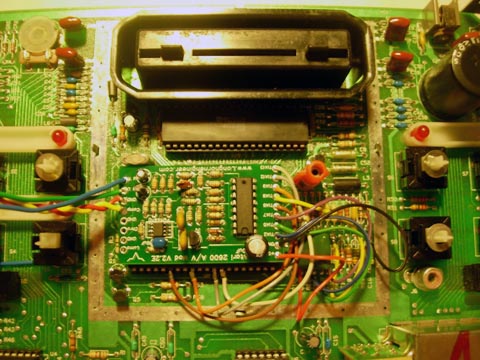
Remove the backing to the foam on the backside of the Video Mod Board and stick the mod on the small middle chip.

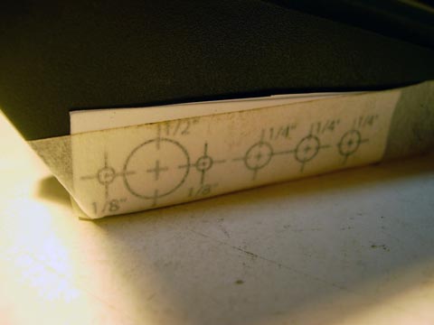
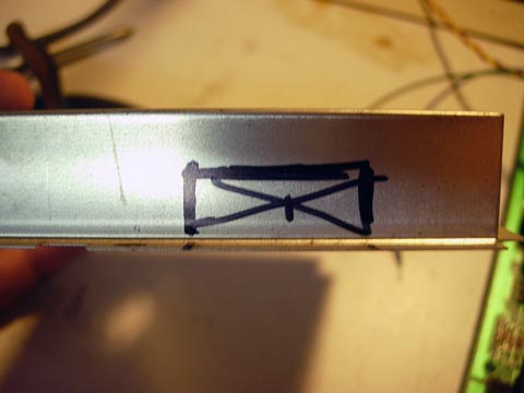
Cut out the drill template on the sheet that is supplied. Tape it to the left side of the bottom of the case as shown. Drill all the holes with a 1/16″ bit first. Then use the 1/2″ and 1/4″ forstner bits to drill the other 4 holes. Last, drill the 1/8″ holes.
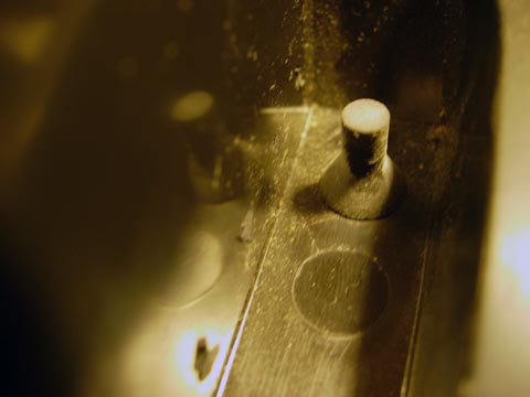
Cut off the top of this rubber stub on the inside near the holes that where drilled.
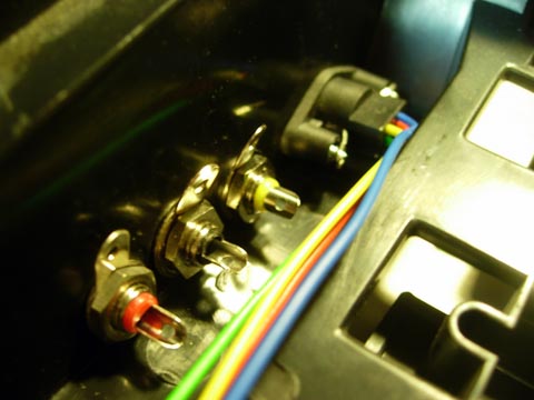
Install the S-video jack and RCA jacks. The RCA jacks have four parts; the jack, a nut, a washer, and a grounding ring. Remove the nut and slide the grounding ring and washer off. Slide the RCA jack through the 1/4″ hole and place the grounding ring then the washer and then the nut on it. Looking from the back the colors go (left from right) yellow, white, red. Tighten the nuts with a 9mm wrench or needle nose pliers.
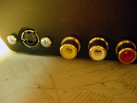
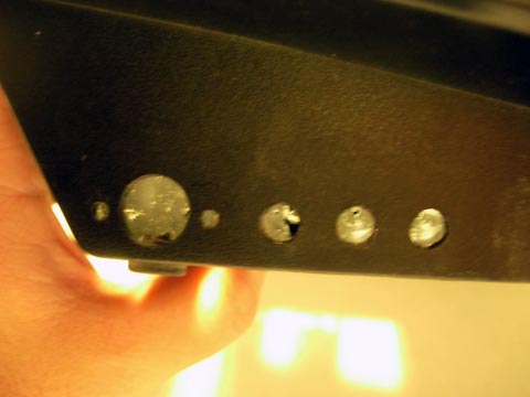
Here is what the outside should look like.
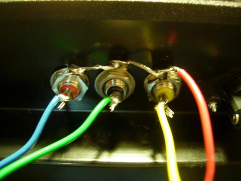
Solder the 4 long 10″ wires to the RCA jacks like above. The red wire goes through all the ground rings.
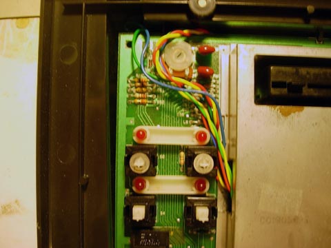
Now attach the S-Video Jack like the above picture. First solder the Green and Red wires first. Then twist the Yellow wire around the Green one and solder. Then twist the Blue wire around the Red one and solder.

Cut a rectangle out of the shielding so the shielding can be replaced. This could improve your picture quality. But it is not necessary. You will need tin snips or a rotary device like a dremel. After cutting put the RF shielding back on the Atari.
Now place the Atari mainboard in the bottom half of the case. There are two switches on the bottom of the case that go through the mainboard. Make sure to line those up correctly. Rout the wires the best way possible. Replace the washers on the push switches. Lastly, replace the cover and the screws.