
Atari 2600 Light 6-switch A/V Install Guide
Read through the instructions carefully before attempting. Also read the disclaimer.
This guide is for the install of the Longhorn Engineer Atari 2600 Video mod for Light 6-switch consoles.
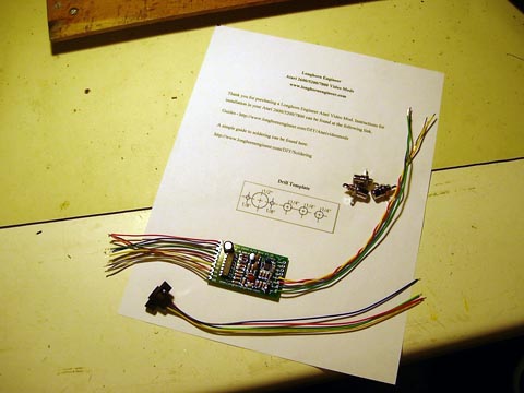
Your kit should contain the following.
1 – Atari 2600 A/V mod board
3 – RCA Jacks
1 – S-Video Jack
2 – Screws
1 – Printout
Tools Needed
Philips Screwdriver
Flat Head Screwdriver
Scissors
Tape
Drill bits
*1/16″ Twist bit
*1/8″ Twist bit
*3/8″ Twist bit
*1/4″ Forstner Bit
*1/2″ Forstner Bit
Electric Drill
9mm Wrench or Needle Nose Pliers
Soldering Iron and Solder
Small clippers
Forstner Bits are preferred over regular twist bits because unlike twist bits they don’t “dig” into the brittle plastic which can cause the case to break. Harbor Freight sells a set of what you need for $10.
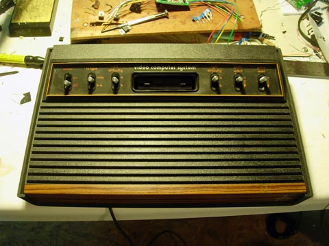
Make sure you have a clear open area to work on the Atari.
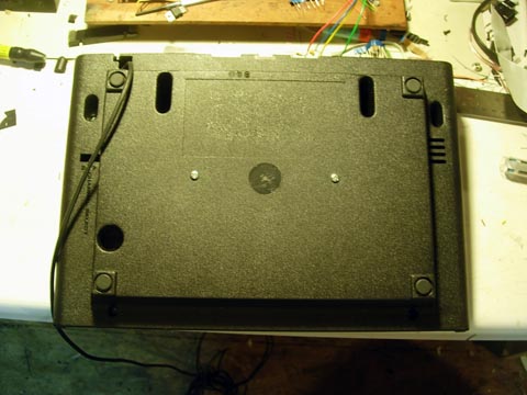
On the bottom side of the Atari there should be 8 screws to remove. Make sure to put these in a safe area and make note which ones go where. Flip the Atari right side up and remove the top.
See the black foam rings around each switch? Remove those and place them to the side where you won’t loose them. Direct your attention to the RF cable on the right side.
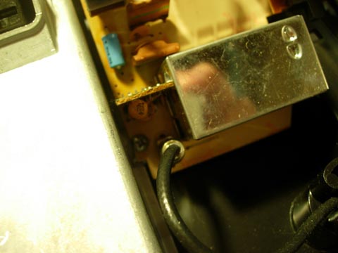
Remove it by pulling straight away from its socket. It should be wrapped around some plastic in the case so unwrap it.
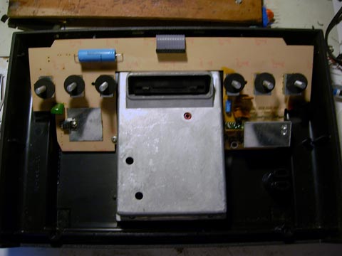
To remove the upper board (one with switches) unscrew the two screws on both sides of the RF shielding.
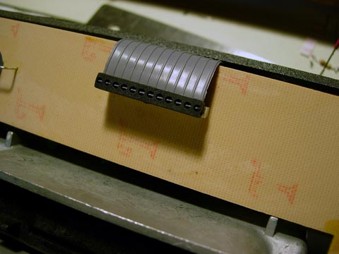
Then unplug the connector cable that connects the two boards together. Remove the upper board and set it a side.
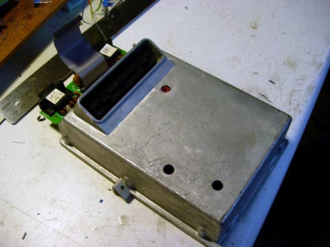
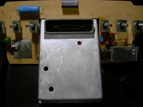
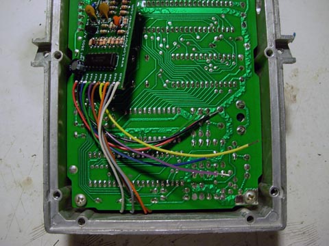
Take the lower board that is inside the rf shielding out of the bottom of the case.
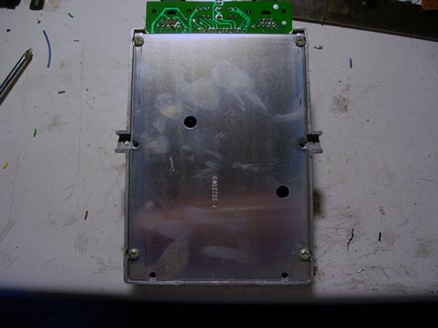
Unscrew the bottom of the rf shielding.
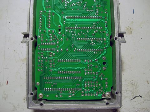
Unscrew the two screws inside that holds the lower board to the rf shielding and lift the lower board out of the shielding.
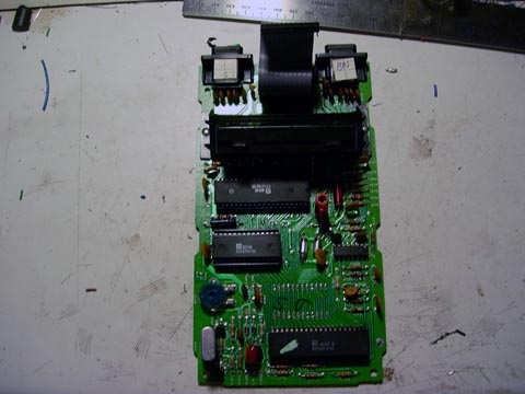
At the bottom of the board there is a large chip. Remove it by sliding a flat head screw driver under it. Make sure not to bend the pins.
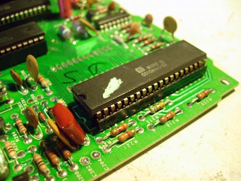
Bend pins 6, 9, 12, 13 and replace the chip in the socket. Place the chip back into the socket.
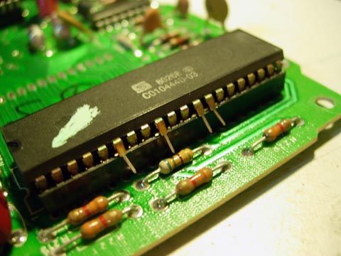
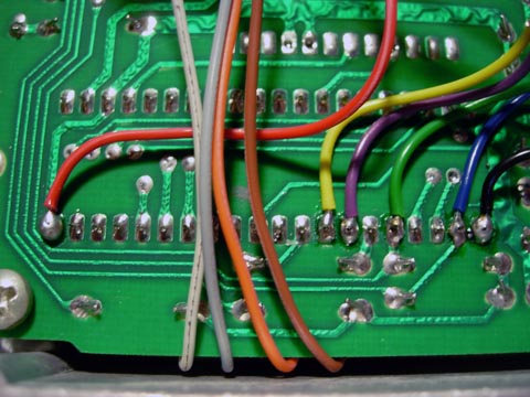
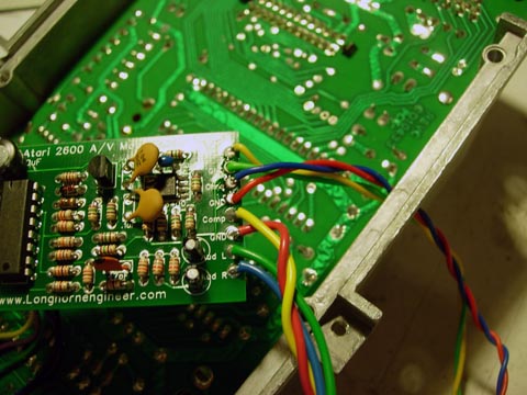
Solder the brown, orange, gray, and white wire on to pins lifted like below.
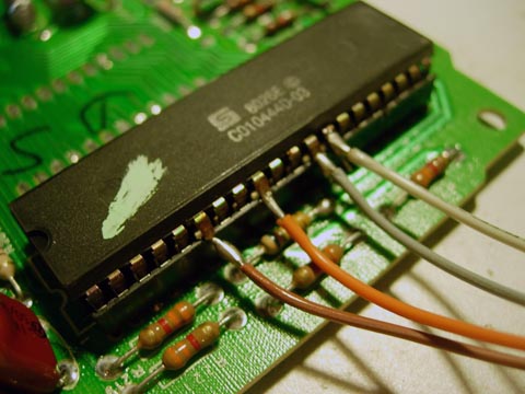
Should look like below.
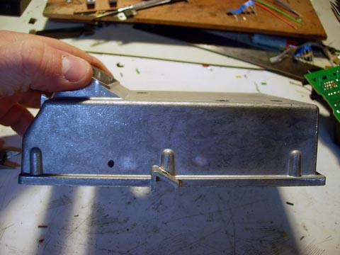
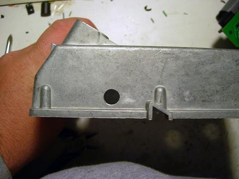
Take the rf shielding and drill a 1/8″ pilot hole and then a 3/8″ hole in the spot marked below.
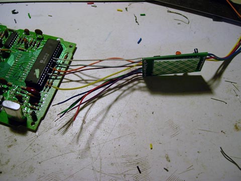
Place the lower board back into the rf shielding and situate the mod like below. Replace the screws.
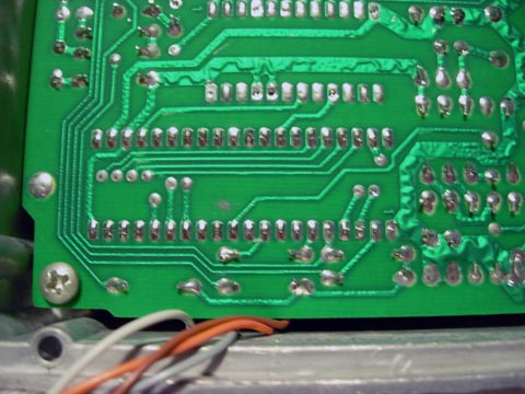
At the bottom row of solder joints is where we are going to solder the rest of the points.
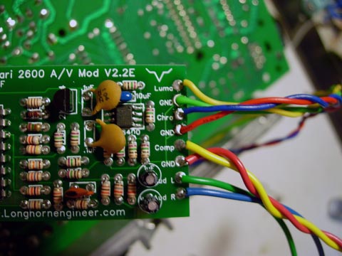
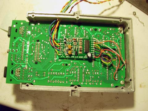
Then pass the S-video jack wires through the hole you drilled in the rf shielding and then solder it to the board like so.
Remove the backing on the sticky foam and press it on the bottom of the PCB. Replace the bottom of the shielding and set it aside.
Cut out the drill diagram and tape it to the back right corner. Drill a 1/16″ pilot drill and then use the Forstner bits to finish the drilling.
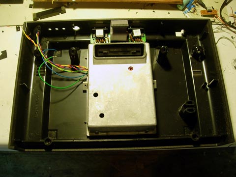
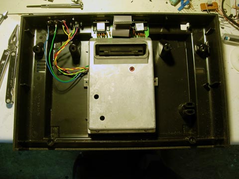
Place the bottom board and rf shielding back in and screw it in from underneath.
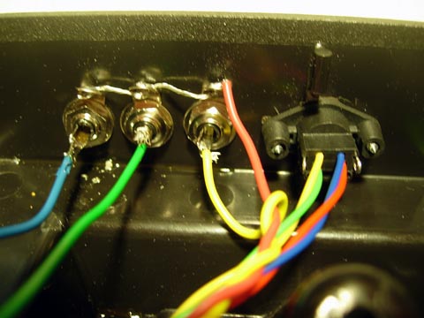
Screw the S-video jack and RCA jacks in place.
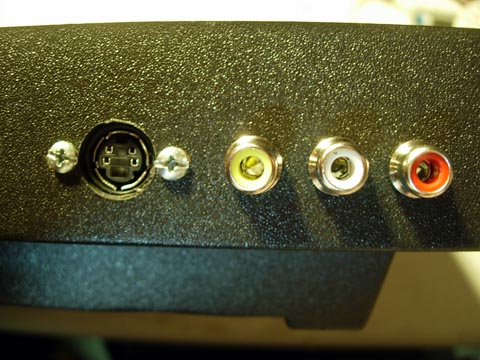
Solder the long wires to the read of the RCA jacks. The Red ground wire goes through all three jacks.
Screw the upper board back on and replace the connector wire.
You are now done with the mod. Replace the top of the Atari and screw it all back together.