
Atari 2600 Junior A/V Install Guide
Read through the instructions carefully before attempting. Also read the disclaimer.
This guide is for the install of the Longhorn Engineer Atari 2600 Video mod for most Junior consoles.
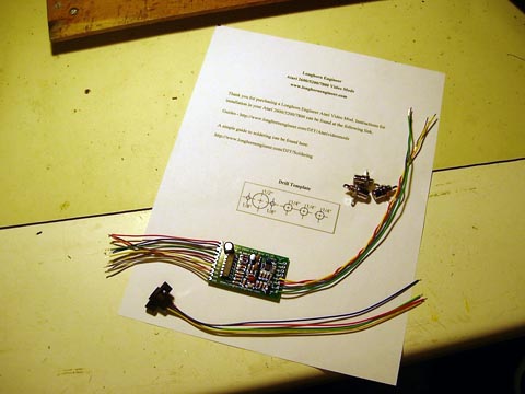
Your kit should contain the following.
1 – Atari 2600 A/V mod board
3 – RCA Jacks
1 – S-Video Jack
2 – Screws
1 – Printout
Tools Needed
Philips Screwdriver
Flat Head Screwdriver
Scissors
Tape
Assorted Drill bits (from 1/16″ to 1/4″)
Electric Drill
9mm Wrench or Needle Nose Pliers
Soldering Iron and Solder
Small clippers
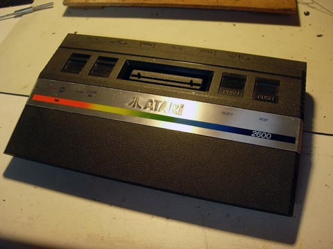
Make sure you have a open, clear area to work on your Atari.
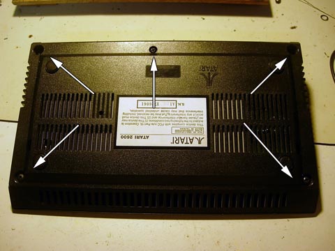
On the underside of the console remove the 5 screws. Be very careful and remove them slowly. The Junior is made out of brittle plastic and the screw posts have a habit of breaking off.
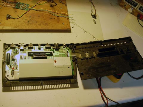
Take the cover off by flipping it to the right. Remove the small ribbon cable by pulling it upwards out of its slot.

Set the top off to the side. To remove the RF shielding the Mainboard will have to be removed. In the lower left and right side of the board there are some tabs that will have to be pulled outwards to free the board.
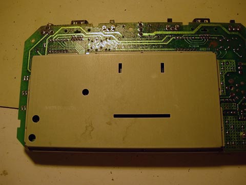
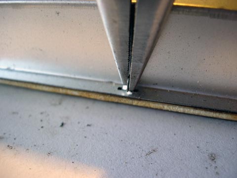
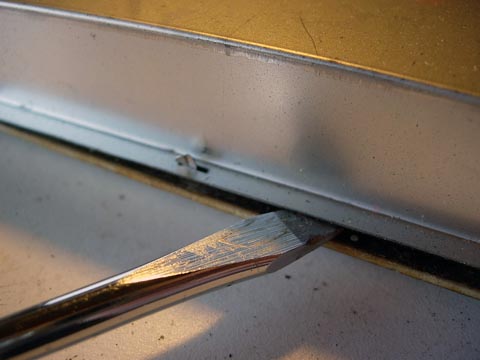
Flip the board over and look along the edges. There are some tabs that are twisted. Take the needle nose pliers and twist the tabs straight. After they are all straight insert a flat head screwdriver barely under the shielding and “pop” the shielding. Do not use excessive force.

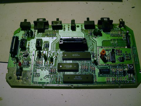
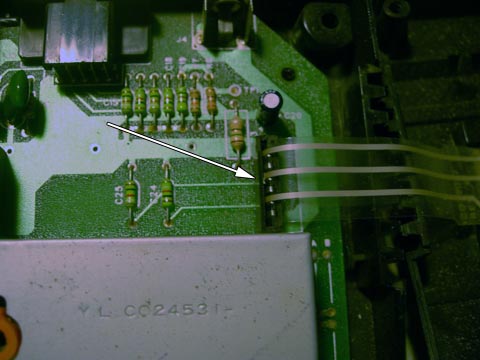
Take a look at the board. The area where the mod will be attached is right below the cart slot.
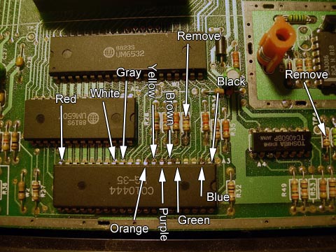
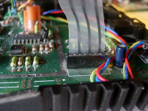
On the left side of the mod board there are 10 short wires. These are the input wires for the mod and should be attached to the Junior using the picture above. The Orange (Pin9), Gray (Pin 12), White (Pin 13) leads of the chip need to be lifted off the board. There is a little guide on how to lift the leads of the chip here.
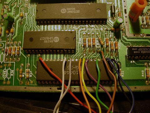
After attaching all 10 wires it should look like the above.
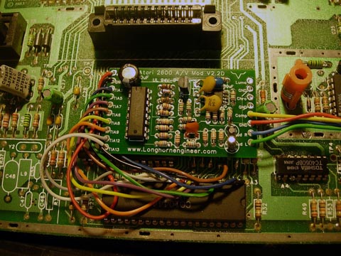
Remove the backing to the sticky foam on the back and stick it to the chip that is right above it like shown.
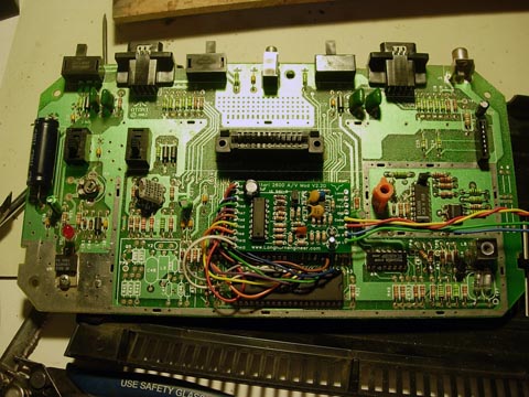
With the mod attached to the Junior it should look like this.
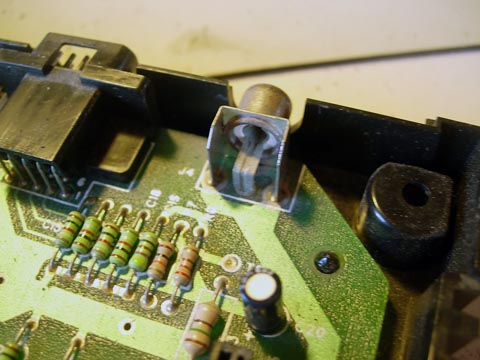
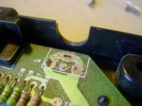
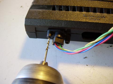
On the top right side of the board is the RF cable jack. Remove this by snipping it off at the base.
This is where we are going to mount the S-Video jack.
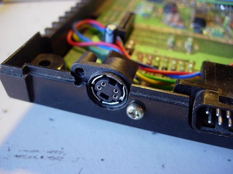
Line up the S-Video jack so it is backwards in the hole like above. It should be tilted at about a 30 degree angle.
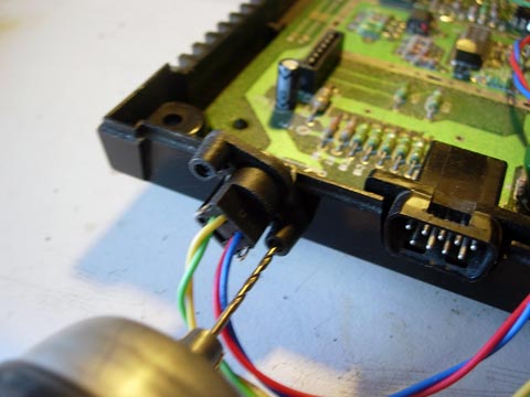
Using a 1/16″ bit and the jack as a guide drill the screw hole. After this hole remove the jack and enlarge the hole to 1/8″.
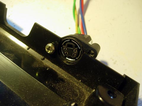
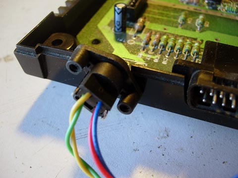
Screw the S-video jack in backwards like above.
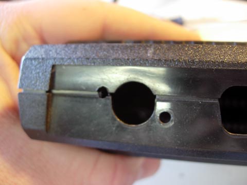
Place the top on and using the 1/16″ bit drill the second hole. Remove the jack and enlarge this hole to 1/8″ as well.
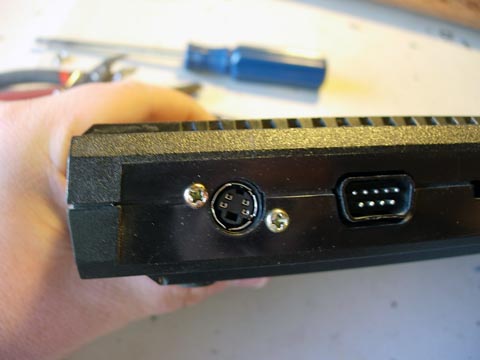
This is what the S-video jack should look like.
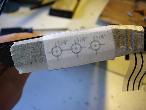
Cut the template out of the printout. You will not need the S-video portion (1/2″ hole). Tape it to the top side of the case near the front right. Start out with 1/8″ holes and then drill out the final size of 1/4″. These are the holes for the RCA jacks.
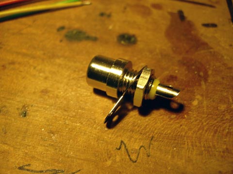
The RCA jacks have three parts; the jack, a nut, and a grounding ring. Remove the nut and slide the grounding ring off. Slide the RCA jack through the 1/4″ hole and place the grounding ring and then the nut on it. Looking from the outside the colors go (left from right) yellow, white, red.
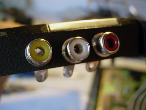
After installing the jacks.
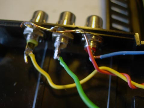
Solder the 4 long wires from the Video mod board to the RCA jacks as shown above. The Red wire must connect all of the grounding rings on the RCA jacks.
Screw in the lower half of the S-Video jack.
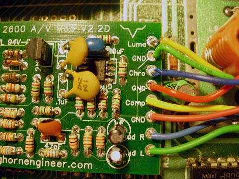
Solder the S-video jack to the Video mod board. First solder the Green and Red wire to there spots. Twist the Yellow wire around the Green wire and then solder it to the Luma spot. Twist the Blue wire around the Red wire and then solder it to the Chro spot.
Stick the ribbon cable from the top side of console into its slot. Make sure it is seated all the way in. Close the console and replace the 5 screws on the bottom.
Screw in the last screw into the S-video jack. The Atari Junior is now done.