
Atari 7800 A/V Assembly Guide
Read through the instructions carefully before attempting. Also read the disclaimer.
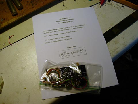
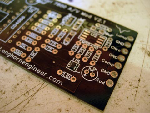
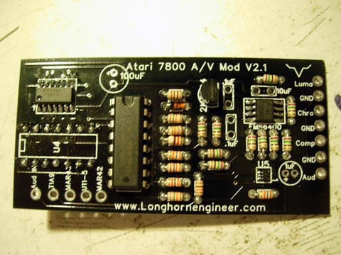
Your Unassembled Kit should look like something above. Check all the parts to make sure you have them all. To sort out the resistors there are some online color band converters like this one.
Parts List
- 100uF Cap 1
- .1uF Cap 2
- 10uF Cap 1
- 1uF Cap 1
- 1N914 (diode) 1
- 2N3904 1
- CD4050 1
- FMS6400 1
- TS5A3159ADCKR 1
- 74AC32 1
- S-Video Jack 1
- RCA Jacks 2
- White
- Yellow
- 14-Pin Header 1
- 14-Pin Socket 1
- A 10″ section of wire
- A 4″ section of ribbon wire
- Screws 2
- Printout 1
- Resistors (in Ohms)
- 1.5K 1
- 10 1
- 9.1K 1
- 75k 1
- 36K 1
- 18K 1
- 75 10
- 2K 1
- 1.6K 2
- 1K 1
- 1.8K 2
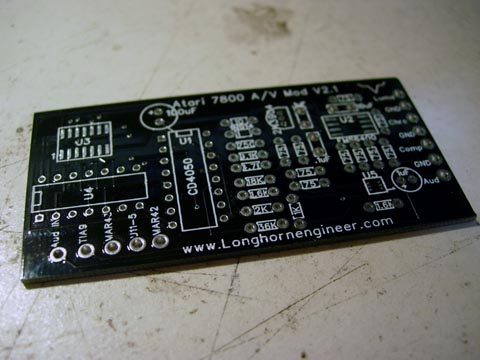
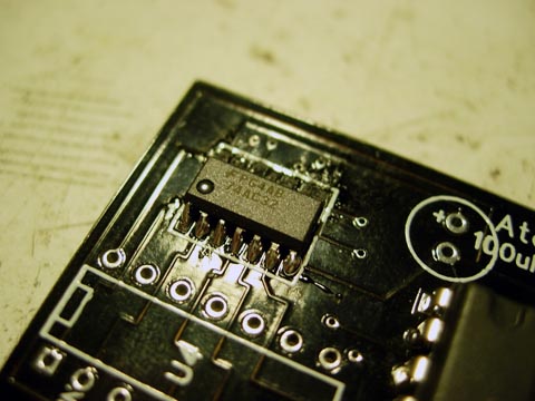
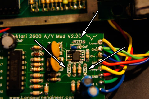
First solder on the TS5A3159ADCKR chip. It is the smallest one and goes in the U5 location on the PCB.
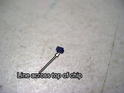
The TS5 chip has a line that indicates the top of the chip and where pin 1 and pin 6 are.
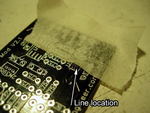
To solder it to the PCB place some solder on the pads on the PCB. Then tape the TS5 chip to the PCB. The line on the chip should face the bottom of the PCB. Make sure the pins are lined up correctly. Place your soldering iron on the legs and heat up the solder that is under it on the pad. After they are all attached test each one with a multimeter to make sure none are bridged and connected to the pad.
Remove the tape and solder the other side of the chip.
Solder the 74AC32 in place in the U3 position.
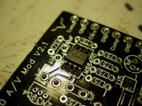
Solder the FMS6400 in place in the U2 position.
Then the CD4050 goes into its spot.
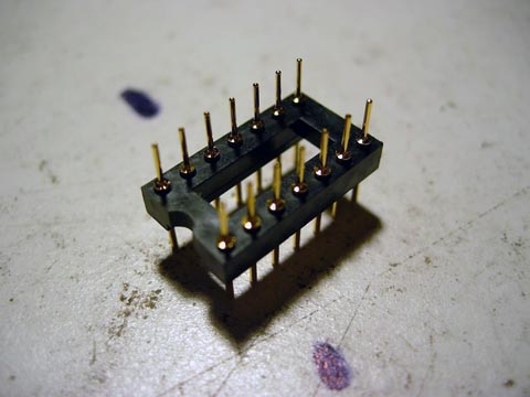
This is the 14-pin header. It gets solder on the under side of the board in the U4 position.
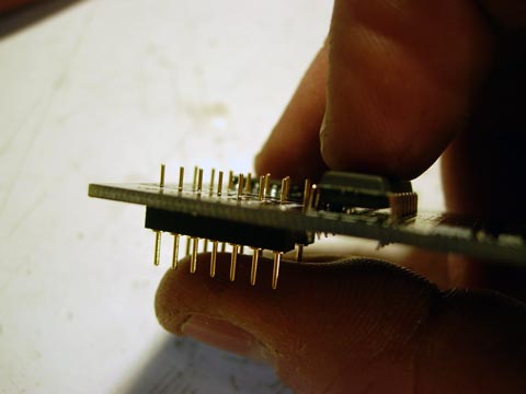
This is how the header gets soldered on.
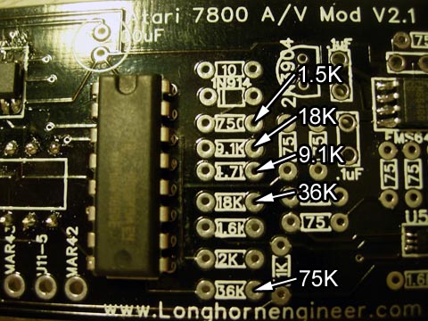
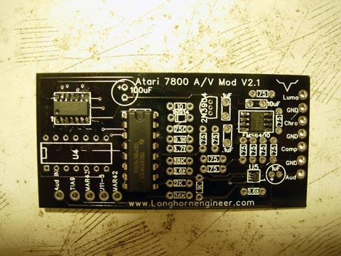
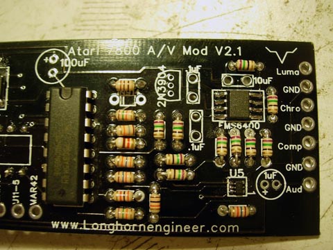
After the header is soldered on solder the resistors in place. There is some errors in the V2.1 silkscreen on the PCB. The corrections are made in the picture above.
I like to solder all the non 75 ohm resistors first as it makes the process a bit faster in terms of soldering and clipping the leads.
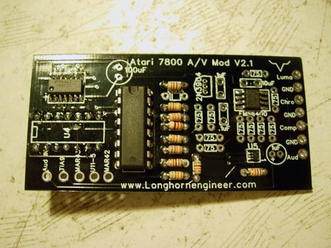
75 ohm resistors soldered in place.
If you have a mod with the newer FMS6410 chip (it has a little dot on it) then do not solder in the 75 ohm in these spots.
Solder the 2N3904 and 1N914 in there spots. Make sure the legs of the 2N3904 are not bridged.
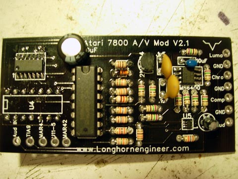
Solder all the capacitors in there spots.
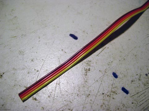
Take the 4″ long ribbon cable and split up the wire. Strip off about 1/8″ on either end.
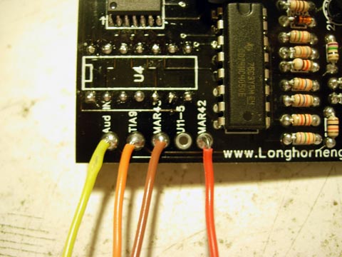
Solder them to the bottom left corner of the PCB as shown above.
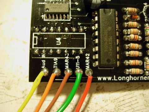
Solder the long green wire to the U11-5 spot.
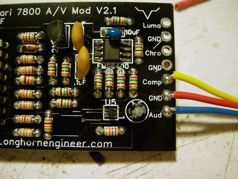
Solder the yellow, red, and blue long wires to the right side of the board to these spots.
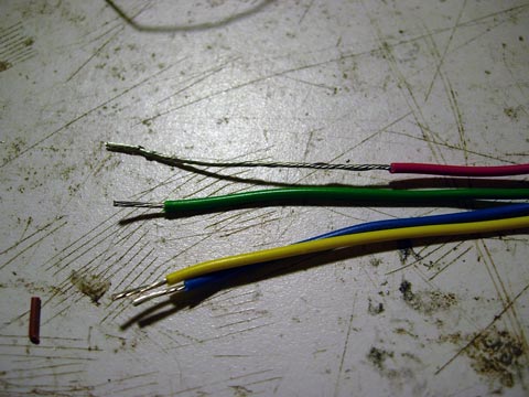
Strip about 1.25″ off the end of the red wire and trim about .25″ off the blue and yellow wires.
Your mod is complete. Head back to the install guides page for instructions on installing the mod.