Replacing Valve Seals

The Wagoneer’s AMC 360 engine is a bit worn out. The engine blows a bit of smoke on start up so I suspected it was the valve seals leaking down some oil into the cylinders when the engine isn’t running. The engine itself doesn’t burn much oil other wise.

The overview is: remove the valve covers, remove rockers and push rods, remove valve stem keepers and springs, install new seal.

Parts / Supplies Needed

  • Valve Cover Gaskets
    • FEL-PRO VS 50001 C
  • Valve Seals
    • EngineTech S2886
  • Sealant
    • Permatex 80062 High Tack Gasket Sealant

Tools Needed

  • Valve Spring Compressor
    • Proform 66784
  • Valve Holder
    • Lisle 19700
  • Air Compressor
    • Fittings to hook up to the valve holder
  • Spark Plug Socket
  • SAE Socket Set

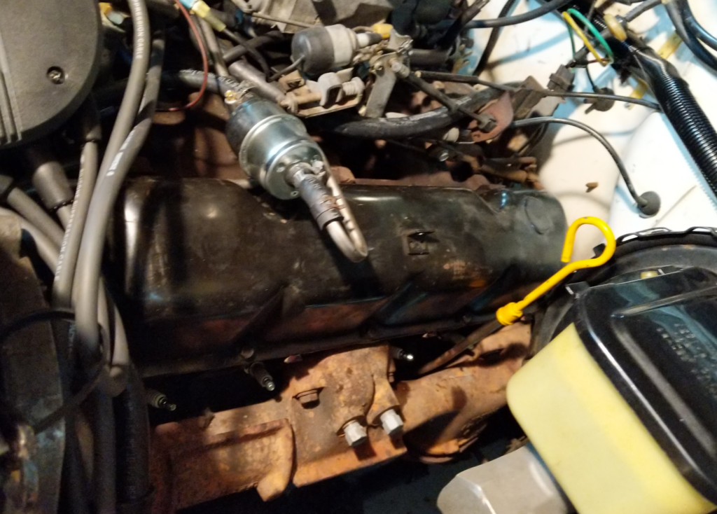
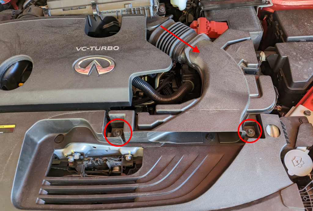
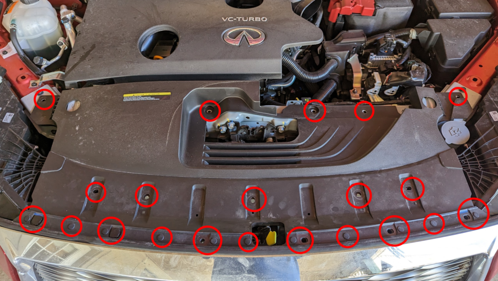
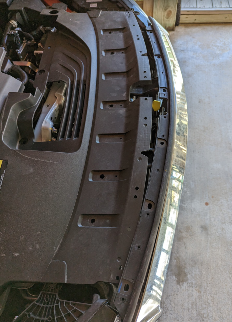
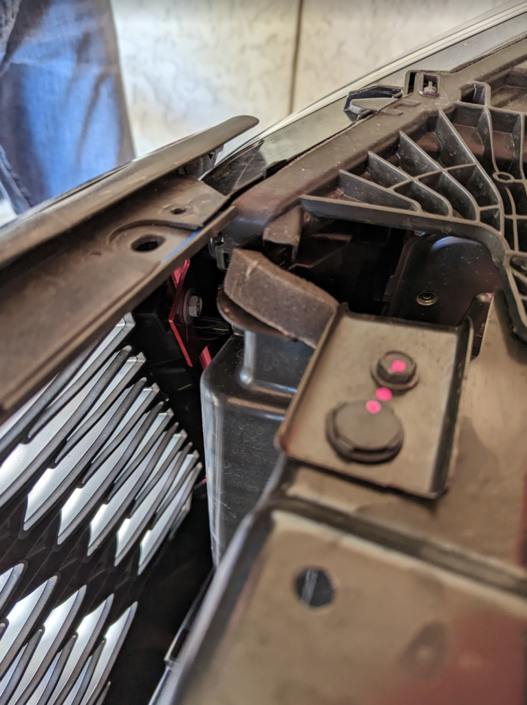
First move everything out of the way of the valve covers. For me the spark plug wires and the fuel lines where in the way so I had to disconnect these and move them out of the way.

Remove the valve cover. Clean up any old valve cover gasket left on the engine and valve cover.

Remove all the spark plugs from the engine. Keep them in order if you are not replacing them.

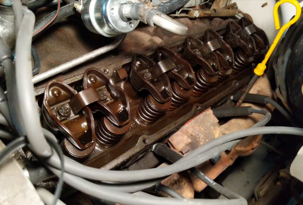
Next we want to remove all the rockers and push rods. To remove the rockers you want both valves to be closed before removing the two bolts holding each rocker pair on. Rotate the crank with a socket and wrench till the valves close (valves up and push rods down) then remove the bolts. Repeat for all 8 of the pairs.

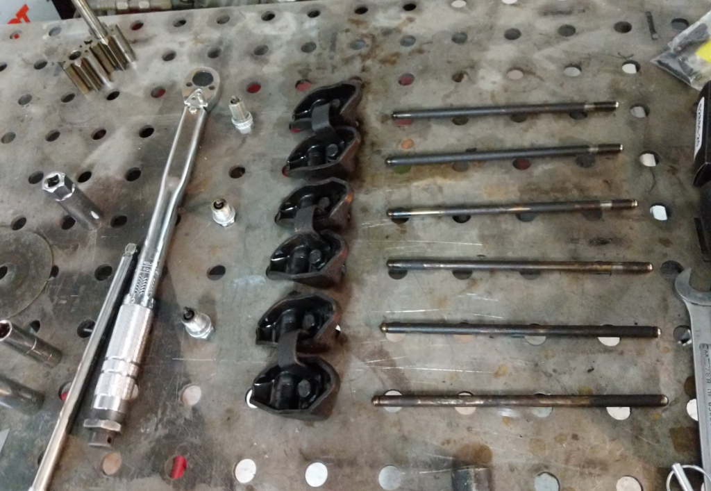
Make sure you keep the rockers and push rods paired up and organized so that the rockers and push rods can go back to the original location when reinstalling.

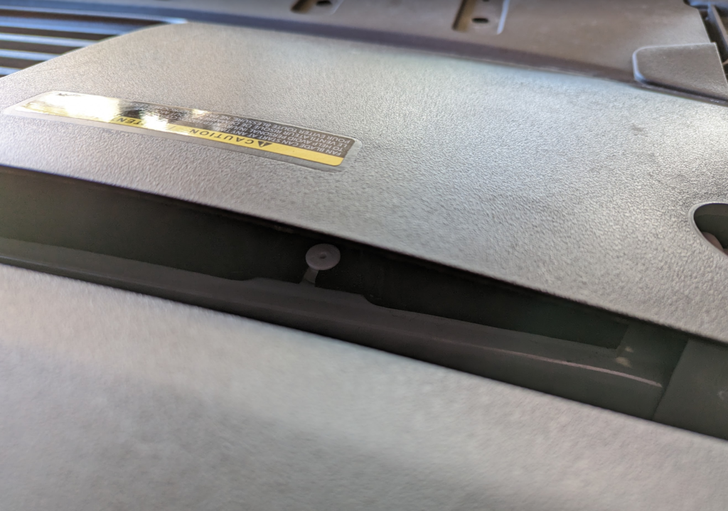
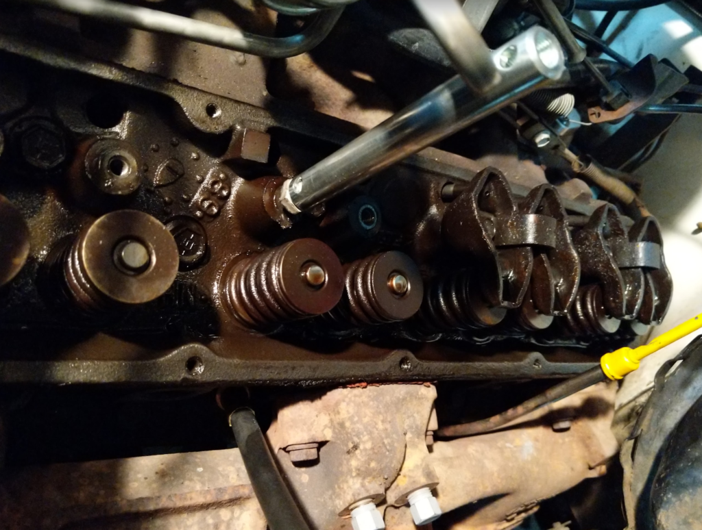
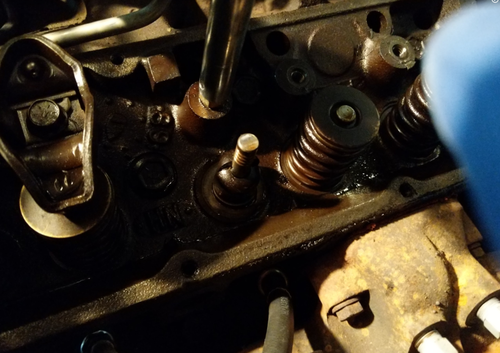
Ok next, thread in the valve holder into the spark plug hole and apply continuous air from the compressor into it. This will hold the valves up while we remove the valve keepers and springs to replace the seal.

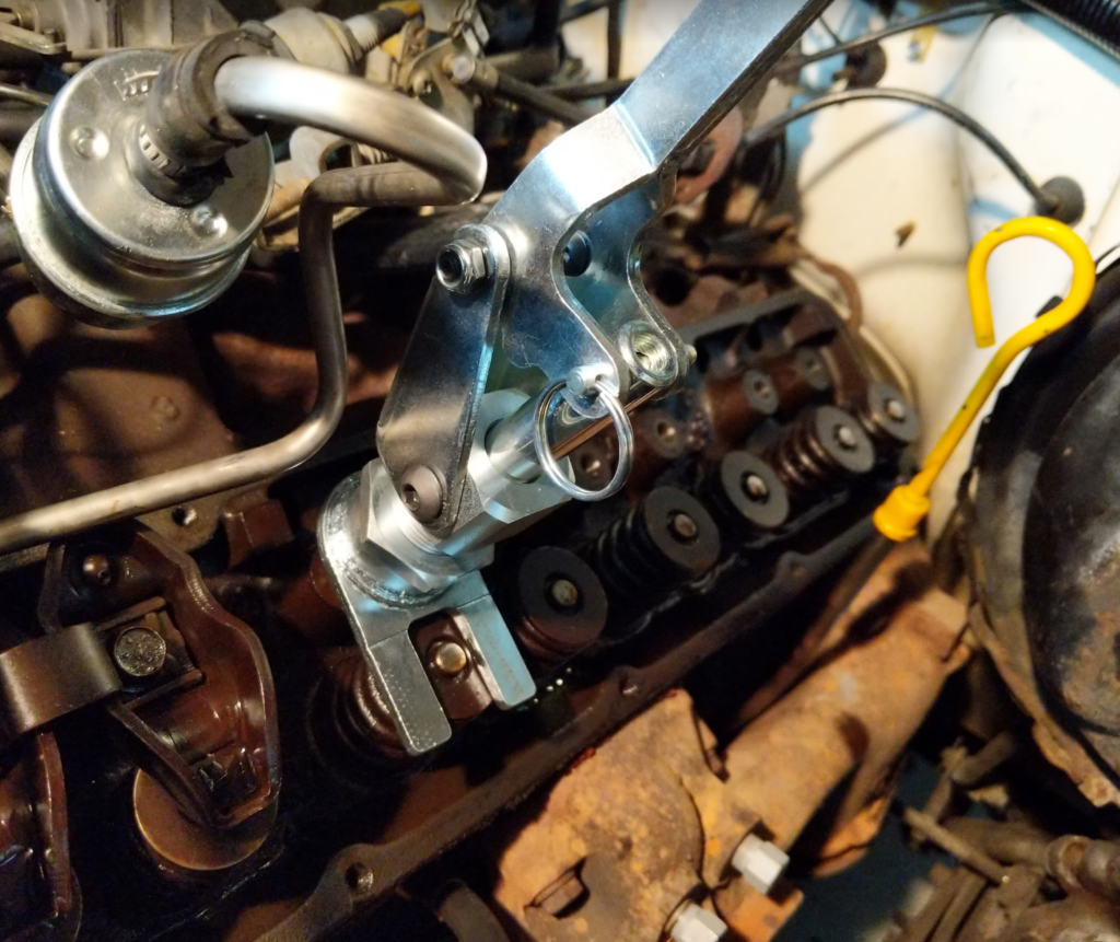
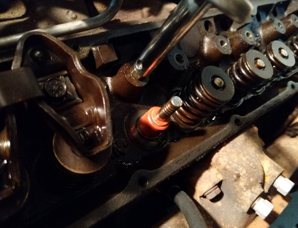
Next, thread on the stem of the valve spring compressor tool into the rocker bolt.

Install the rest of the valve stem tool over the stem.

WHAT EVER YOU DO. DON’T PRESS DOWN ON THE VALVE STEM. JUST THE SPRING.

Pressing down on the valve stem will break the seal of the valve and then the valve will drop into the cylinder. If that happens…. Time to order head gaskets and bolts.

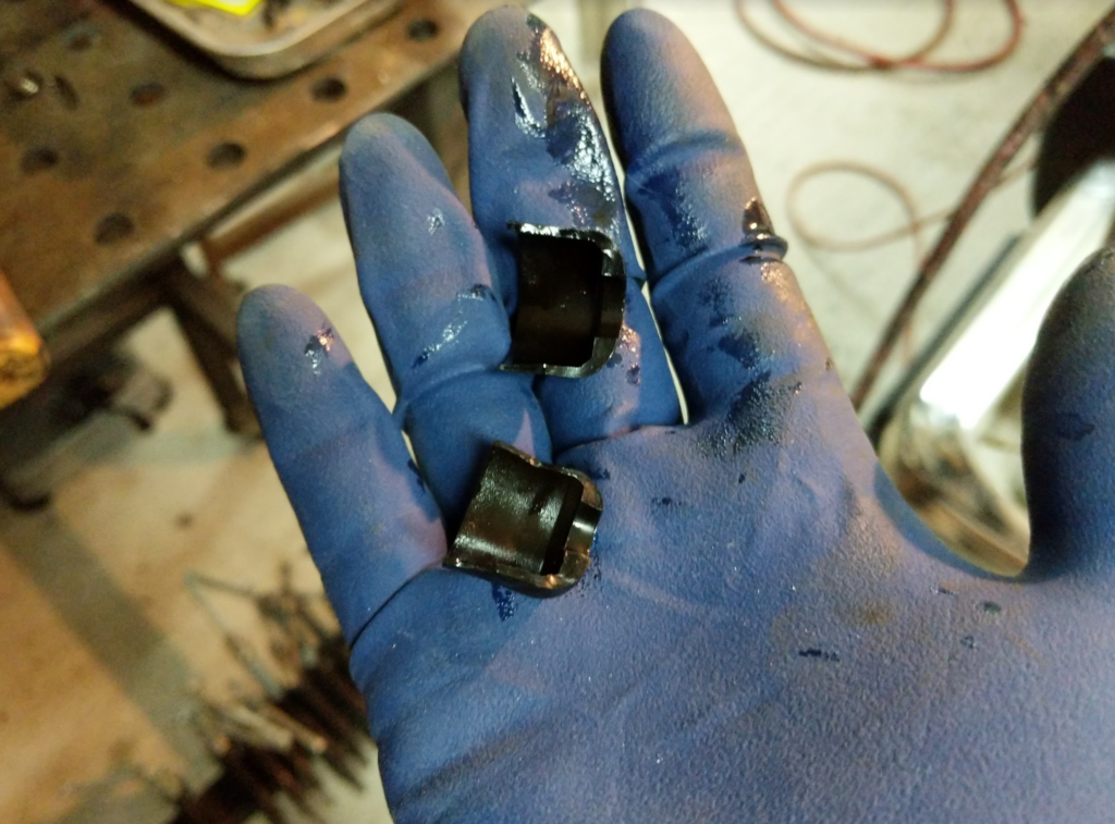
Pull on the valve compressor and it will press the top of the valve down. This will compress the spring around the valve stem. The valve keeper is two parts around the valve stem. Make sure you don’t loose them when they come loose from the valve stem.

Starting compression
Fully compressed with valve keepers removed

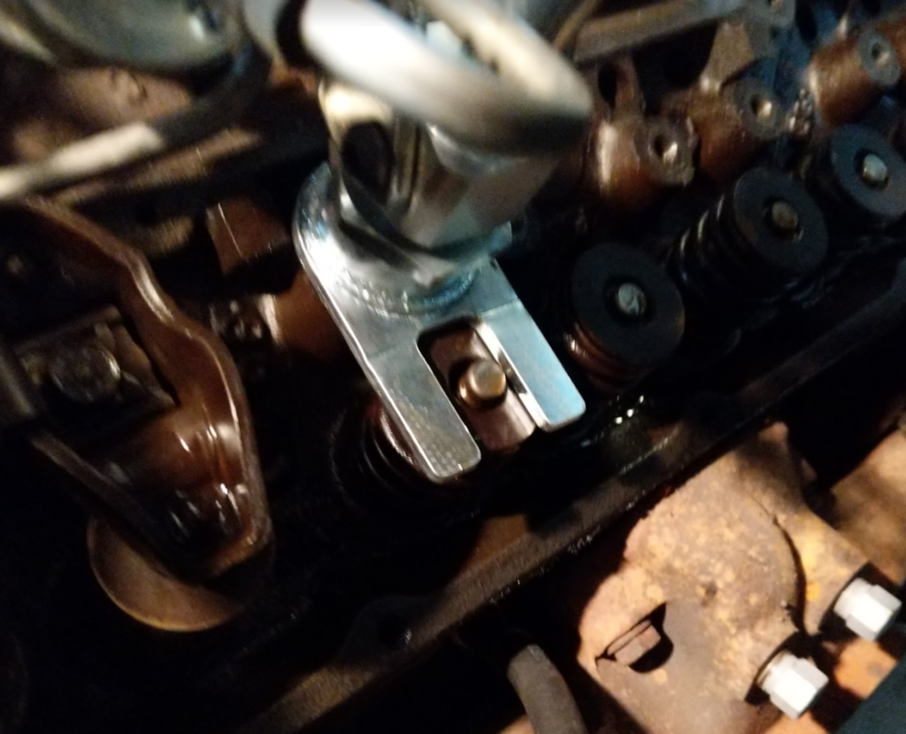
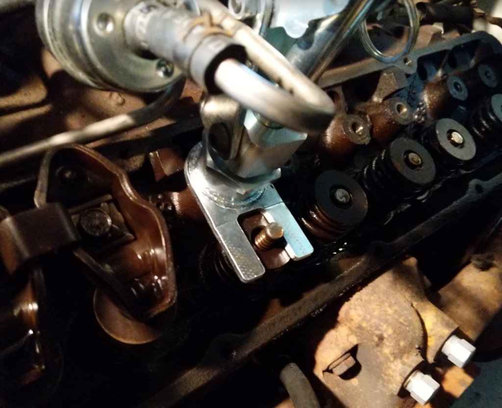
Once the valve keepers are removed, release the spring tension and remove the valve compressor tool. Then remove the valve spring.

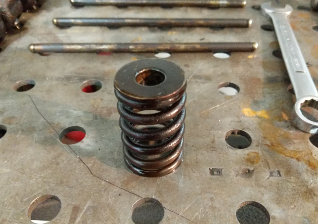
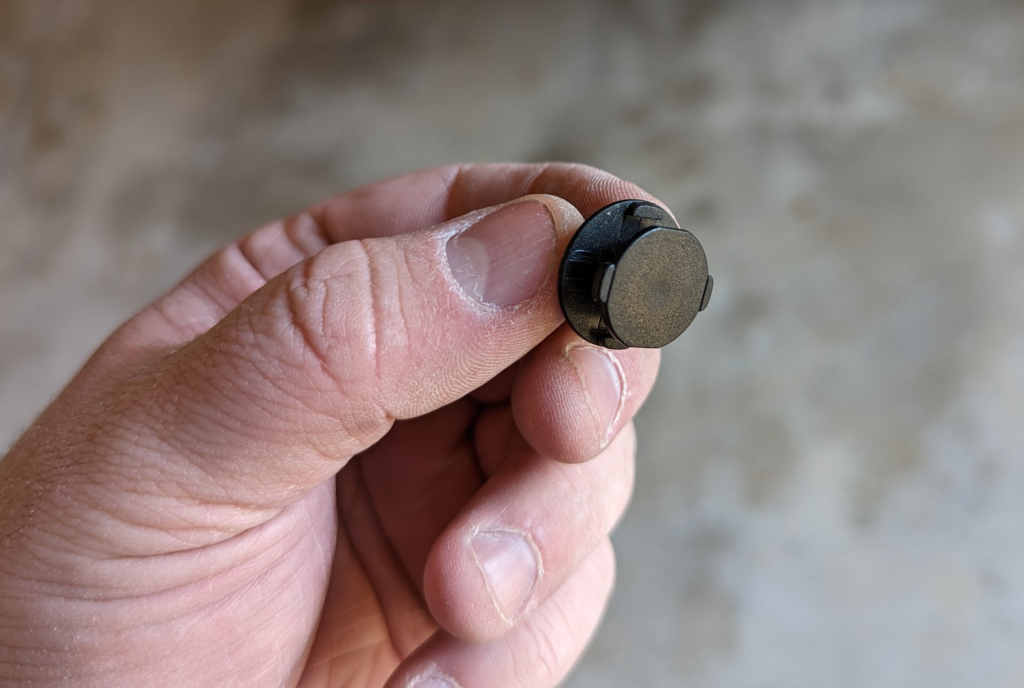
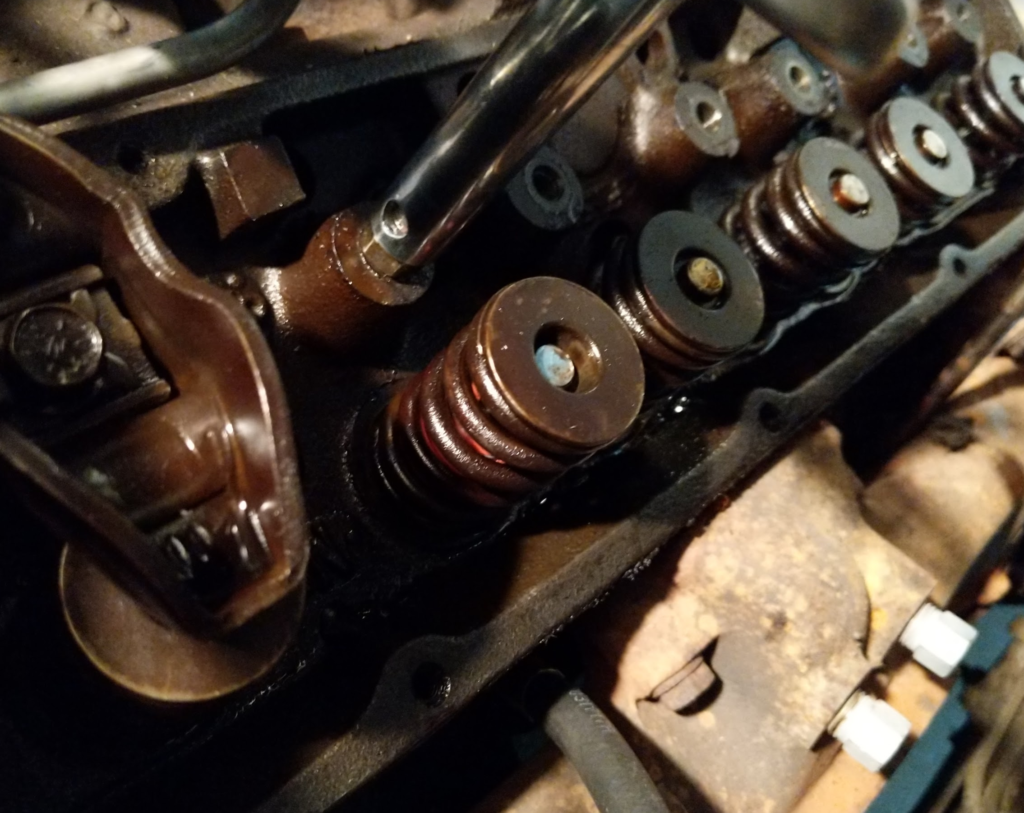
Here, remove any of the valve seals that still exist. Mine where all cracked or missing.

I don’t know if the original valve seals where hard plastic or just the rubber hardened up over the years but all of mine where shattered.

Slip on the new valve seals which are silicon with a spring to keep them in place.

Replace the valve spring.

This is the most difficult part, use the valve spring compressor to compress that spring down and then with your other hand…. handle the two pieces of the valve keeper and hold them on the valve stem. Slowly release the compressor as the valve keepers set.

Do this 15 more times.

Then reinstall the pushrods and rocker arms back to the original locations. When installing the rocker arms, you need to make sure the valves are closed, just like when removing the rockers. What I like to do is to install the pushrods and rocker arms and then screw down the rocker arm bolts till I can tell what position the valves are in. Rotate the crank till both valves are closed and then torque to spec… which is 19ft lbs.

Then replace the valve covers. I like to use a high tack sealant to hold the cork to the valve covers while installing. Valve cover bolts are torqued to 45in lbs. Remember inch pounds!

Reinstall the spark plugs and send it!

Oscillators and Twisted Nematic Effect Displays

For the Cat Feeder Unreminder, I am going to pivot from using LEDs to indicate the “feeding” status and use a TN-Effect Display instead. These displays are much lower power then illuminated LEDs but they require slightly more circuitry to drive.

TN LCDs run off low AC voltage from around 3VAC to 6VAC depending on the screen. The one I picked, Varitronix‘s VI-422-DP-RC-S, operates over this range. They are not particular picky about the quality of AC voltage, just that it has zero DC offset. Driving the displays with square waves seems common. Anything north of 50Hz should do as well.

This application note from NXP shows how to drive these displays from logic level DC devices like microcontrollers.

Looking in my spare parts bin I found some old CD4049 hex inverters that I made into a simple RC based oscillator.

I used a 0.1uF capacitor and a 100K ohm resistor. Should get the oscillator to jiggle around 70Hz. Then I fed the output of the oscillator into another inverter on the CD4049. This gives me two square waves that are out of phase which will give us the AC voltage we need!

Circuit breadboards and driving the display. Spaghetti!
Output of the Oscillator circuit. Ended up being 53Hz. Loose tolerance capacitor!
Channel two in purple here shows the output of the out of phase signal that is generated from running the output of the oscillator into the inverter.

This works great! However the downside is this oscillator uses ~120uA at 3.3V without driving the Display. The display takes sub 5uA to drive so this is a big part of the power budget!

We will need another way to generate the AC voltage! Metacollin from the MacroFab Slack Channel suggested using a low power comparator in a relaxation oscillator configuration. This will get us to around 1uA in current draw if we use a MAX9019 dual comparator chip.

I am also looking for a way to measure currents that low. My Siglent SDM3045x is a bit out of its league at this point!

Replacing a Grille on a 2022 QX55 Infiniti

A couple months ago, someone backed into my mother’s brand new QX55 Infiniti and cracked the front grille surround. There is not a lot of repair videos or information about the QX55 since it is in its second year of production. Lets figure out how to replace the grille!

Part Number T99G7-5VG1A is the “blacked” out version of the standard chrome grille. It is the color my mother wanted.


Damaged original grill. Less then 2000 miles on the car and some turd bucket backed into it.

Open the hood and remove the air scoop thingy with a 10mm socket. Then pull the scoop boot off the intake.

Now you will want to remove the plastic cover by removing a bunch of push pins.


Easiest way to remove these is with a plastic pry bar from an interior trim removal tool kit.

After removing all the push pins, the plastic cover will feel like it wants to pop out but there is one more fastener that we can’t get at. It is under the plastic cover near the caution sticker on the cover.

You can’t remove this without damaging either the plastic cover or the fastener. So you will have to pop the front side of the cover out and then slide the cover out of that fastener.

Pull the front grill outwards while using your plastic pry bar to pop the plastic around. The top plastic cover should come free now. Set it aside.

There are 4 10mm bolts that hold the grille to the rest of the body panels. They are in the corners of the grille. Here is a picture of the upper passenger side bolt that needs to be removed. A 10mm ratchet wrench is key here. Don’t drop the bolts.

After removing the 4 bolts, there is a wiring harness on the driver side of the grille for the front camera. Disconnect the connector and pop the connector off the mount. There is also a zip tie holding the cable to the bottom of the grille, cut the zip tie.

With the bolts and cables removed we can start unclipping the grille. There is 2 clips on both the driver and passenger side of the grille and then 8 along the bottom. If you get your finger on the outside of the clip and press in they should snap out. Doesn’t take a lot of force.


Here is a picture of the clips and that zip tie you need to cut. You want to press the clips inner part towards the center of the grille.

Another close up of the clips. Here you can see the inner “ramp” part of the clip you need to press in.

Grille removed!

Where the bolts and wiring harness is located at.

Here are the location of the clips.

We now need to pull of the logo and front camera. Logo unscrews from the back with two phillips screws and the camera requires a T10.


New grille with the camera and logo transferred over. You will need to pull the connector clip from the original grille as well.

Install is the exact opposite: pop the grill into all the clips on the body, reinstall those 4 10mm bolts in the corners, slide the top plastic cover into place. Pay attention to that one white plastic fastener that we couldn’t remove. The cover kinda just slides into place around that one. Reinstall all the push in clips and the air intake snorkel thing with the 2 10mm bolts and shut the hood!

Grille fixed and look updated!

Sony PS FL-1 Repair?

My record player (Sony PS FL-1) stopped opening and closing recently. Only reasonable thing to do is to open it up and see what went wrong. The PS FL-1 is a “tray” style record player. Kinda like a CD player.

Well that is the problem. Looks like the travel switches for the tray broke apart. The actuator on one of the switches was stuck closed which probably caused the tray to break the switches.

Alps switch manufacture, part number is 205-11 403R. Google doesn’t turn up anything and I couldn’t find anything on Alps website about this part.

Fortunately I found someone selling the entire switch board for $15 on ebay. Will update when I reassemble the turntable.

Checker Gas Tank Repair

Pulled the gas tank from the Checker. It has rust pin holes and is in rough shape. Original or NOS (new old stock) are really expensive so lets try to save the original.

Pulled the tank and removed the sending unit which had a cork float! The tank looks like it had some damage from a road hazard strike near the original fuel pickup so we will need to repair that as well.

Repairing the bulk of the pin holes was done be flowing leaded solder into them. The above picture is the factory drain that was in the tank where most of the pin holes where located at. The tank is made out of pressed steel that was then soldered/brazed together with lead. Repairing with lead is the “obvious” choice. Use lots of acid based flux!

The original fuel pickup was torn off the tank. I used the lead solder to reattach it. I am not going to use the original fuel pickup so I put a 1/4″ NPT plug into the hole.

After all the repairs where done, I de-rusted the tank with muriatic acid and rinsed with a metal prep (mastercoat metal prep). Before I can epoxy coat the inside of the tank, it needs to be super dry. Hair dryer in the tanks intake tube works like a treat.

Jumping ahead a bit…

Painted the tank with Steel-It stainless paint after removing most of the exterior cruft with a brass wire wheel. I then welded in a backing ring for an in tank fuel pump module from Tanks Inc.

What the tank looks like now. The insides are coated with POR15 tank liner. Hope it lasts!

1965 Checker Marathon

This is my 1965 Checker Marathon I picked up in 2019.

Originally a straight 6, Chevy 230 powered car with a 3 speed manual with optional overdrive. Rear gear ratio was the optional 4.10 gears. Optional Fairfield Blue paint. None “energized” 4 corner none adjusting drum brakes.

Basically one of the cheapest Checkers spec wise but has a fancy paint!

The original engine is there but the water jacket is rusted to crap.

Day I brought it home.

My plan is to take it all apart and restromod it. I want to keep it a straight 6 powered car so I have a chevy 292 I6 that will bolt right up to the original borg warner T86 transmission.

Interior before I took it apart.

I also plan on running a turbo on the 292 with multi point injection. Will be an interesting build :)

Ideas on running a Reflective LCD display?

For the Cat Feeder Unreminder, I originally wanted to run LED indicators but I think it would be cool to run a reflective LCD display like on solar powered calculators.

For a display I was looking at Varitronix‘s VI-422-DP-RC-S. I was thinking I can hardwire the display to say FEED. What is weird with these displays is they run on alternating current (AC).

The solar power subsystem provides 3.3VDC which won’t work for activating the segments. Google searching around shows that these displays run on AC square waves. Initial thoughts are to make a push/pull transistor circuit that can drive and source high and the low side can sink giving us a 3.3V AC drive source.

But after chatting with some folks I think using a 4049 Hex Inverter like this will work great.

AEM10941 Evaluation Unboxing and Setup

Received the 3AAEM10941CPCX10 evaluation kit for the AEM10941 solar harvesting chip today.

Box the kit came in. Surprised how “plain” the box is. Usually manufactures for evaluation kits have fancy boxes with branding on it so it can be viewed from the engineer’s storage shelf ;) .
Inside. There was some bubble wrap I removed to keep everything from being shaken around.
The super caps that come with the kit. Part numbers: DMT3N4R2U224M3DTA0 and DMF3Z5R5H474M3DTA0.
The demo board and quick start guide.
Two different kinds of solar panels. An Outdoor (smaller size) and Inside (larger size) type of panel.
Part numbers for the solar panels are LL200-2.4-37 for the indoor panel and MPT2.4-21 for the outdoor panel. From the little bit I know about solar panels is that these are probably tuned to the light frequencies of there environment.
The demo board. Quality of assembly isn’t the best. Jumpers are not soldered straight. Biggest one is the STATUS[2] pin on the upper right of the board. Also, the board’s jumpers are not set out of the box for the given example. Annoying to say the least.
First step on firing up the the demo board is to set these CFG pins. Shown is how mine arrived. You need to set the jumpers to CFG[2] = 0, CFG[1] = 1, and CFG[0] = 1.
Next, solder one of the super capacitors to the back side of the board as shown. I used the DMF3Z5R5H474M3DTA0 which is the larger of the two.
Set the BAL jumper to connect BAL to ToCN. BAL is the balance pin of the super capacitor. These super capacitors are actually two cells in series and the balance pin is the connection between the two.
Then attach the solar panel to the SRC terminal. To see if there is voltage output I put a LED across the LVOUT. The LVOUT voltage regulator is set to 1.8V which is below the forward voltage of the LED I chose.

Its possible it won’t light up right away. It takes sometime for the super capacitor to charge up. You can charge up the super capacitor with a power supply set to 3.3V and current limited to around 10-20mA. Make sure to not reverse bias the charging!

Voltage across the super capacitor while charging up off the solar panel!

AEM10941

The AEM10941 is a solar harvesting IC. It handles a small solar panel and charges either a lithium battery or a super capacitor. I ordered a evaluation board (part number: 3AAEM10941CPCX10) to test it out for the Cat Feeder Unreminder but I went ahead and made a footprint for it in Eagle. The evaluation board comes with a couple solar panels and some super capacitors to mess around with.