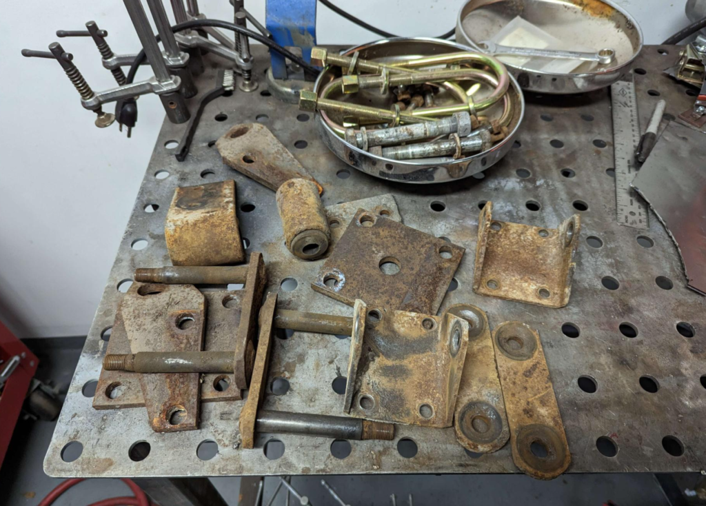
Today I used my vapor hone to clean up the rear leaf spring hangers and brackets.
After about an hour of blasting in the vapor hone and the parts are rust free!
I will be painting these with the AG111 paint system. I have used it in the past on my Mother’s golf cart I rebuild and it has held up to salt spray down on the beach with no problems.
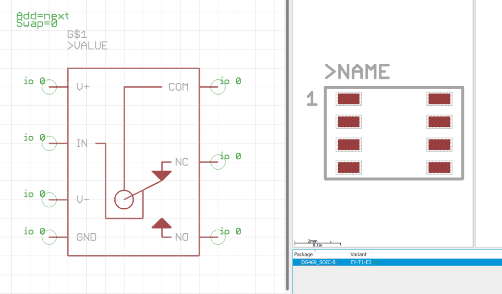
The DG469 is an analog switch that can be controlled with digital signals. The switching part of the chip is bi-direction which is perfect for switching analog signals.
The DG469 designed in Eagle in the SOIC-8 package.
I will be using this IC to switch which segments on the TN LCD get powered up. The NC (Normally Connected) will send power to the “Don’t feed” notification state. The NO (Normally Open) will send power to the “Feed” notification state.
It also has very low power requirements which will be perfect for my project.
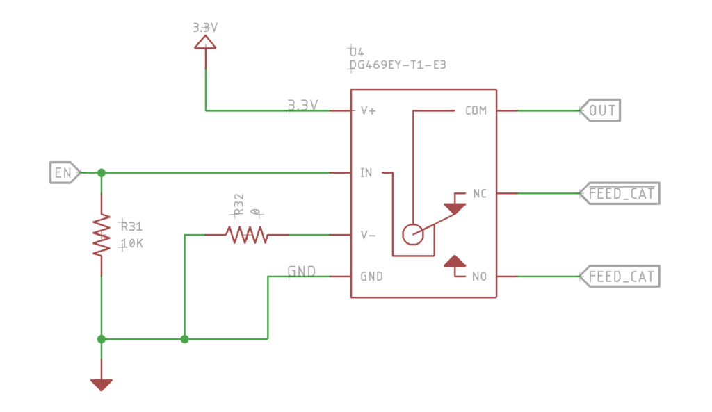
Here is the schematic for the DG469 for the Cat Feeder Unreminder.
I put V- to ground through a jumper because the datasheet isn’t very clear on how to set it up for unipolar power supplies. Gives me a chance to change what that voltage is.
The original headliner for the Jeep Wagoneer was moldy and sagging. To fix this, I had to build my own complete headliner. I didn’t take any photos during the build but I will explain the process and materials I used.
Materials
Coroplast Plastic Sheeting
2-4mm thickness, thinner is better
This is the new backer material for the headliner, it is the same material political yard signs are made out of
You can order this from a local sign shop
Foam-Backed Automotive Headliner
Try to find a Made in the USA material as the imported stuff tends to fall apart
DAP Products Weldwood Landau Top & Trim HHR Solvent Type Spray Grade Contact Adhesive
You want this stuff and not the kind already in spray cans
Need a spray gun that can handle the thick glue, I used an HVLP gun with a 2.0mm nozzle
You want a really good paint respirator when spraying this stuff
A high quality fabric you want to put over the foam
I went to my local fabric store and picked enough out to cover everything
Make sure its wide enough!
Process
Take the old headliner out of the vehicle.
Remove what is left of the foam material off the old backer material. Be careful to keep the original backer in tact, it will fall apart if you let it.
Use the original backer as a pattern and trace it out on the Coroplast. Orientate the Coroplast’s corrugations so they go lengthwise (Front to Back) to the vehicle.
Cut out the Coroplast with a utility knife.
On the parts where the Coroplast needs to bend or curve, cut through only through the top side of the Coroplast. This way it can bend or curve downwards. You might need to make multiple cuts to get the curve to match the original.
Lay out the headliner foam and cut it to match your Coroplast, leaving about an inch all around the border.
Spray down the contact adhesive in sections and press the headliner foam into the Coroplast. I tried to do it without stretching material.
Let the contact adhesive dry.
Trim the headliner foam to match the Coroplast.
Lay your fabric over and trace it out, again matching your headliner and leaving about an inch all around the border.
Spray down the contact adhesive in sections and press the fabric into the headliner foam.
On the edge of the fabric, glue this with the contact adhesive to the backside of the new Coroplast backer. You might not be able to fold over the edge if you are using thicker (4mm) Coroplast as it wont fit into your trim pieces.
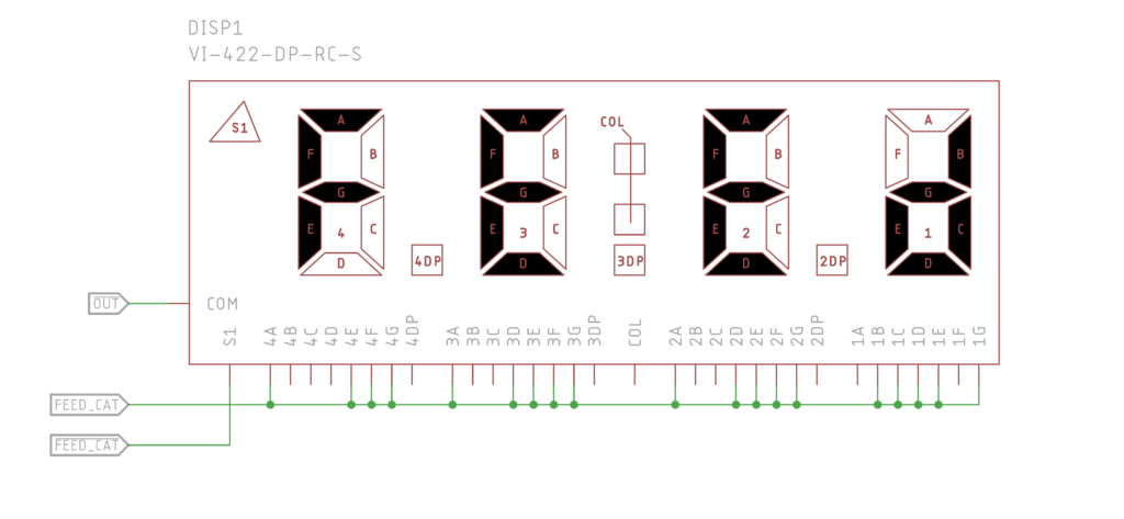
The CFU (Cat Feeder Unreminder) will notify the user that it is safe and timely to feed the cat through a use of a TN style LCD. These are typically a 7-segment style instead of graphical. The CFU also needs to notify the user that the device is still operating.
The common (COM) pin of the display will be directly connected to one leg of the oscillator circuit. Depending on where the other leg of the oscillator is routed, the display will either show “FEEd” or will light up the S1 segment.
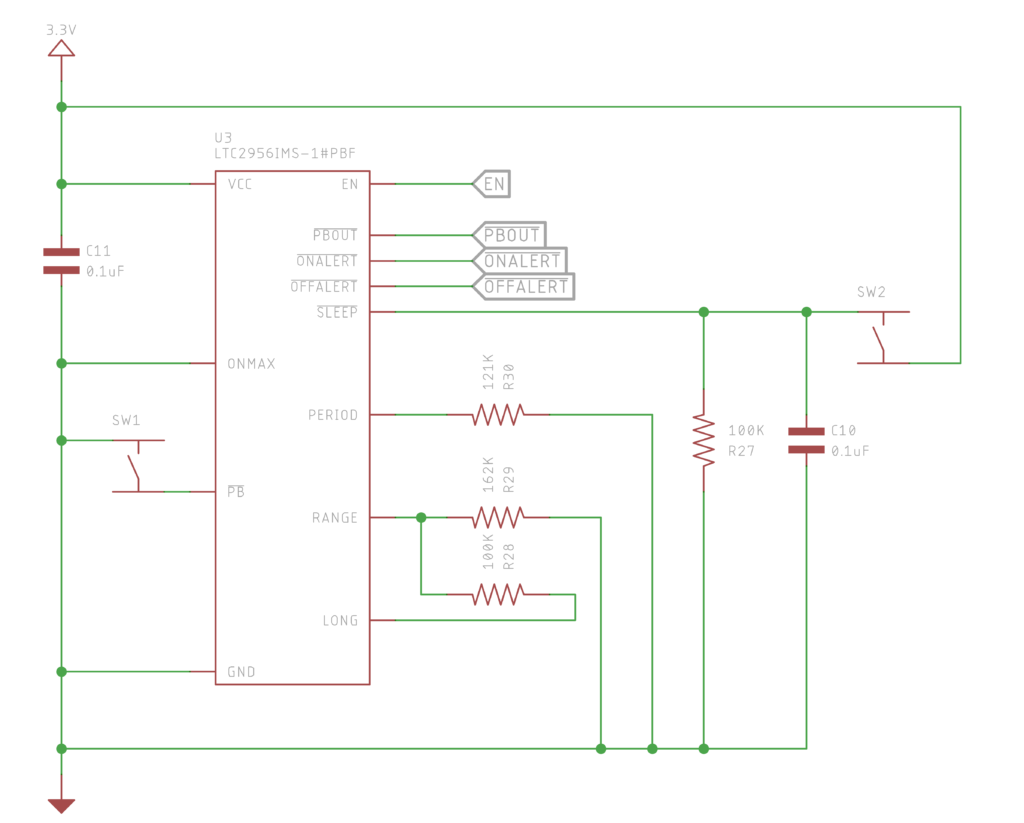
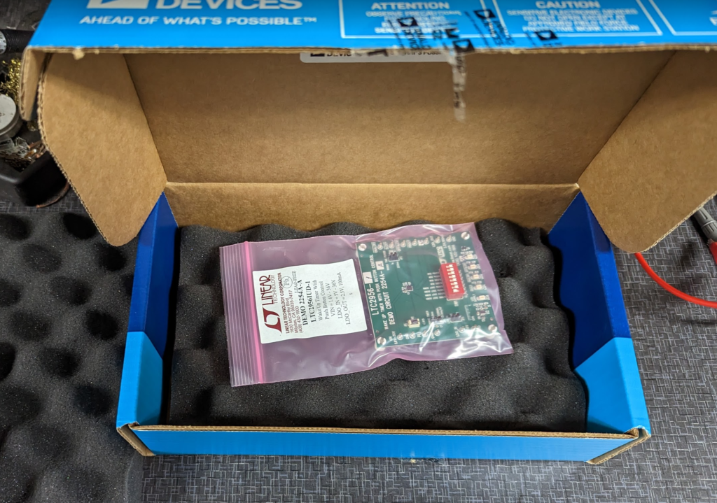
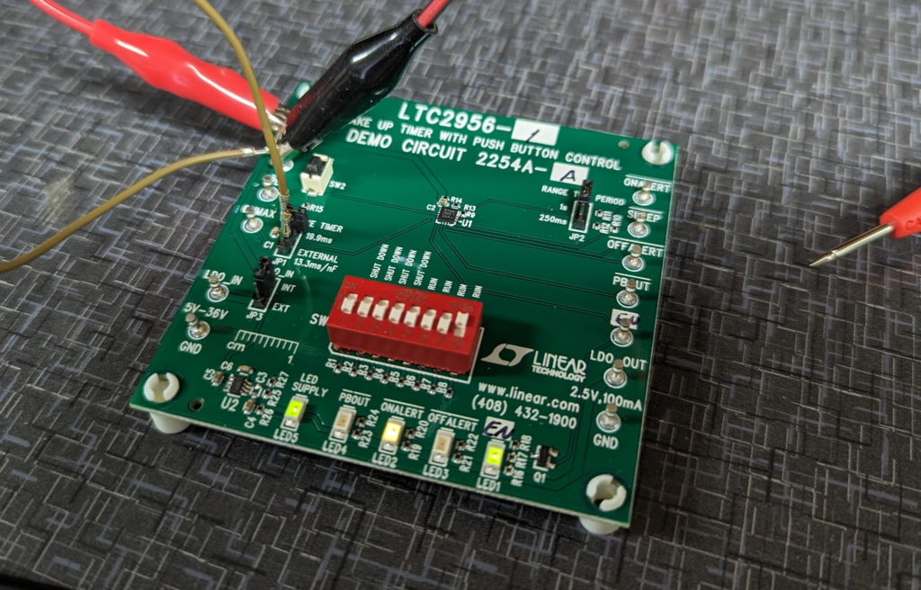
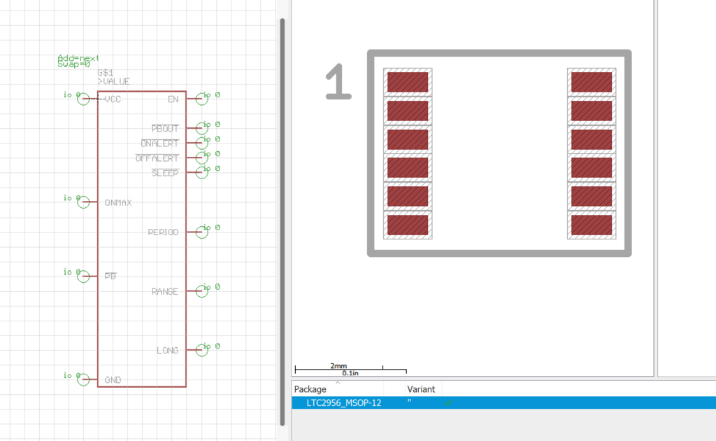
Based on my testing of the evaluation board, this is the schematic for the LTC2956 I am using in the Cat Feeder Unreminder.
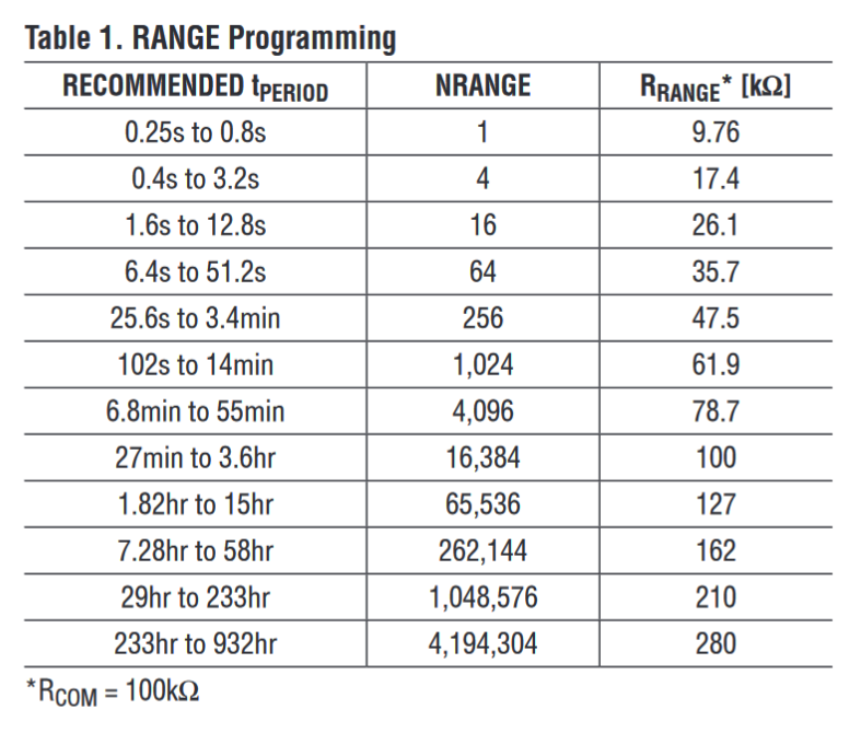
The resistor from RANGE to LONG pin is set to 100K ohms. This is specified in the datasheet.
To set the actual time for the timer to activate the EN pin (t PERIOD), You need to first select the range resistance from the chart below. In my case I want to activate every 22hrs. 162K ohms is the resistor I chose which sets NRANGE to 262,144.
To calculate the period resistor, this is the formula provided by in the datasheet.
RPERIOD = 400 • tPERIOD/NRANGE
For 22hrs, tPERIOD becomes 22 x 60 x 60 x 1000 = 79,200,000. This gives an R PERIOD of 120,849.609 ohms. I picked a 121K ohm resistor.
To send the device into the sleep state, I tied the SLEEP signal through a switch to VCC (3.3V). This brings SLEEP high on button press. When the button is released, SLEEP has a falling edge which is what the LTC2956 is looking for to send it into the sleep state.
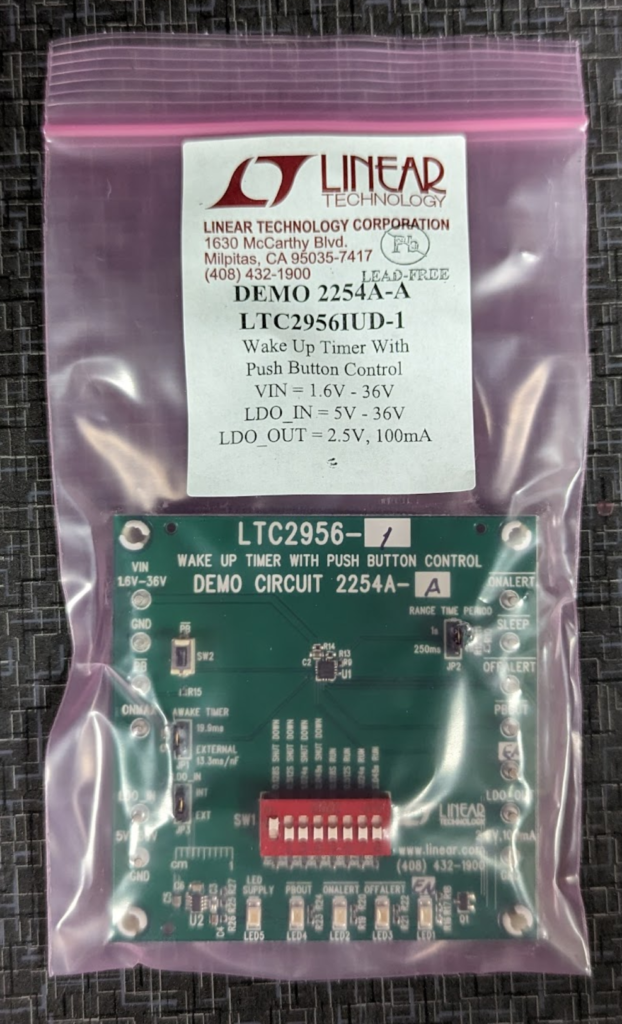
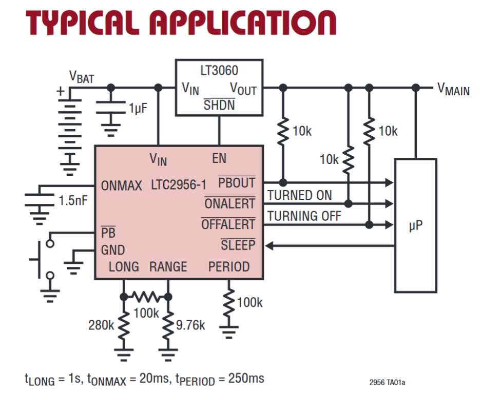
For keeping the time for the Cat Feeder Unreminder I am planning on using the LTC2956-1 which is a super low power timer that has push button reset control. It can accurately handle very long timers that a traditional RC style timers (think 555 timer) wouldn’t be able to do.
For my use case, I am going to pull ONMAX to GND which will disable the timer that turns off the AWAKE timer. I will toggle the Sleep pin from low to high to low to reset the timer.
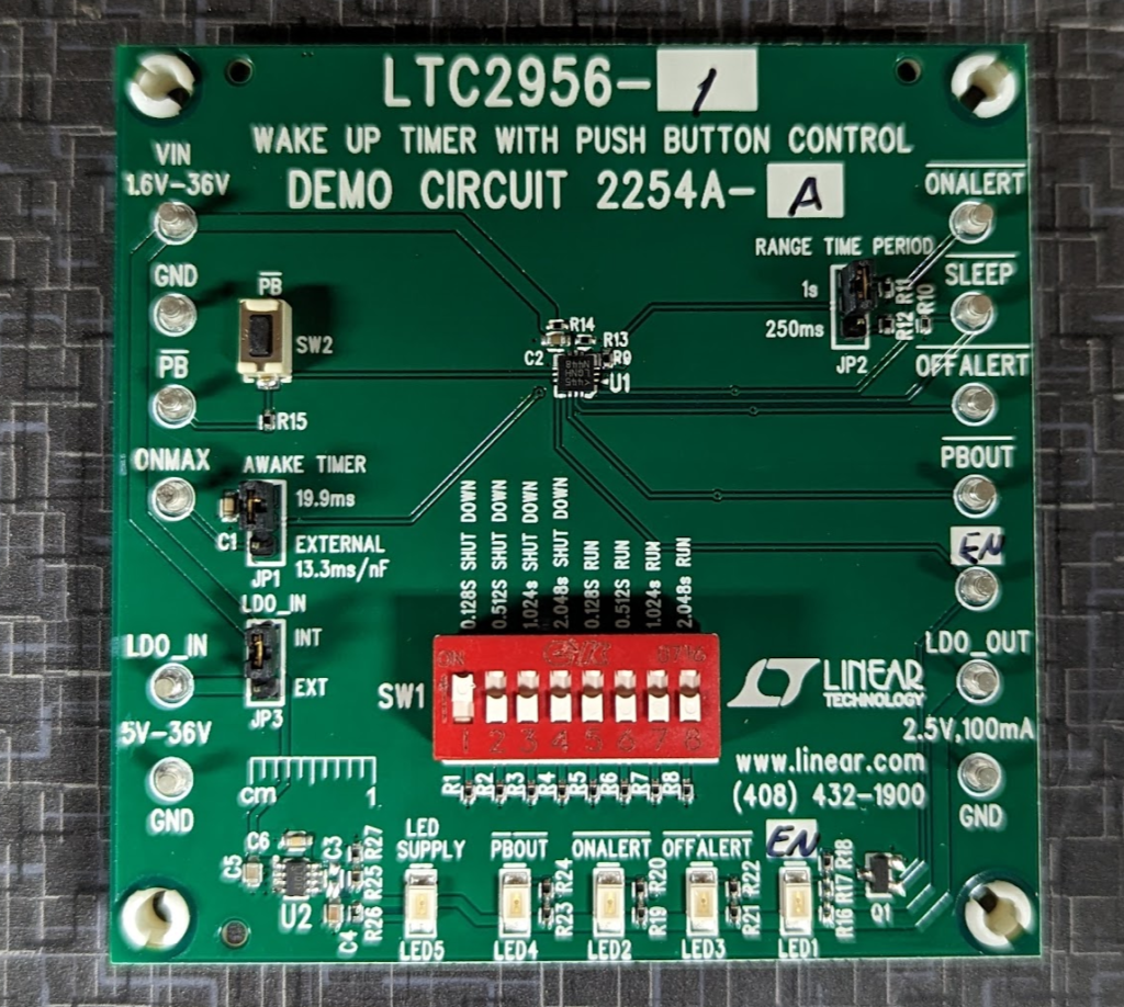
To handle the timing aspect of the Cat Feeder Unreminder I am going to use the Analog (It is actually a Linear Technology part!) LTC2956 timer component.
This is a wake up timer IC that has built in push button support for reset. Perfect for this project.
The timer itself is configured with just a few resistors and can range from 250ms to 39 days. Setting it to the required 22 hours is a piece of cake for this timer.
In shutdown, it only pulls 800nA while active and 300nA in shutdown mode which is one of the lowest current use for a timer that I can find.
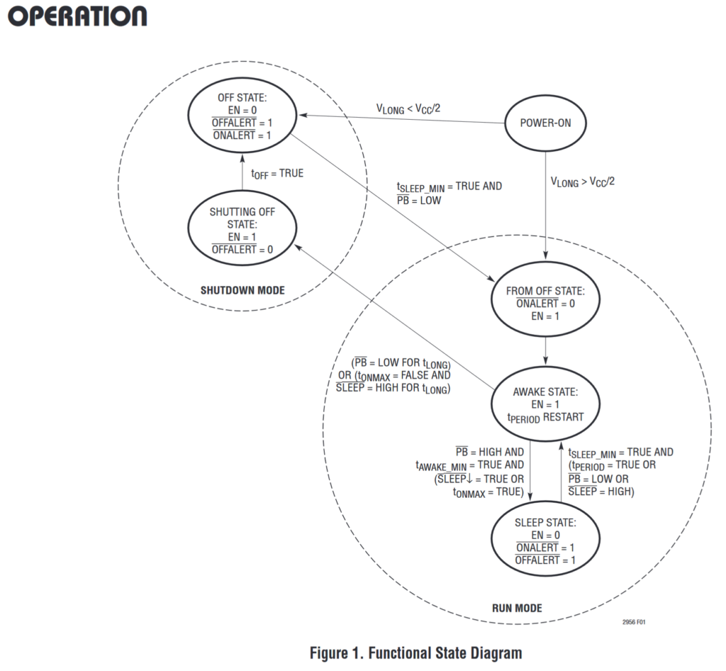
To set this up for the Cat Feeder Unreminder we need to stay in RUN MODE. The device can’t leave SHUTDOWN MODE without interacting with the PB switch and that would make for a hungry cat. The AWAKE STATE with EN=1 is when the device will tell us to feed the cat. SLEEP STATE with EN=0 is in standby counting till next feeding
ONMAX to GND
This sets the T ONMAX time to the max
T ONMAX will stay FALSE
We don’t want the device to auto fall into the SLEEP STATE
SLEEP to a switch
We will use this to send the device to the Sleep State
Active Lowq
Set LONG to max time
Tie PB HIGH
Makes sure we don’t fall into SHUTDOWN MODE
Set Period/Range for timer to activate in 22hrs
This should allow the EN pin to go high every 22 hours and will reset low when the push button on PB is pressed.
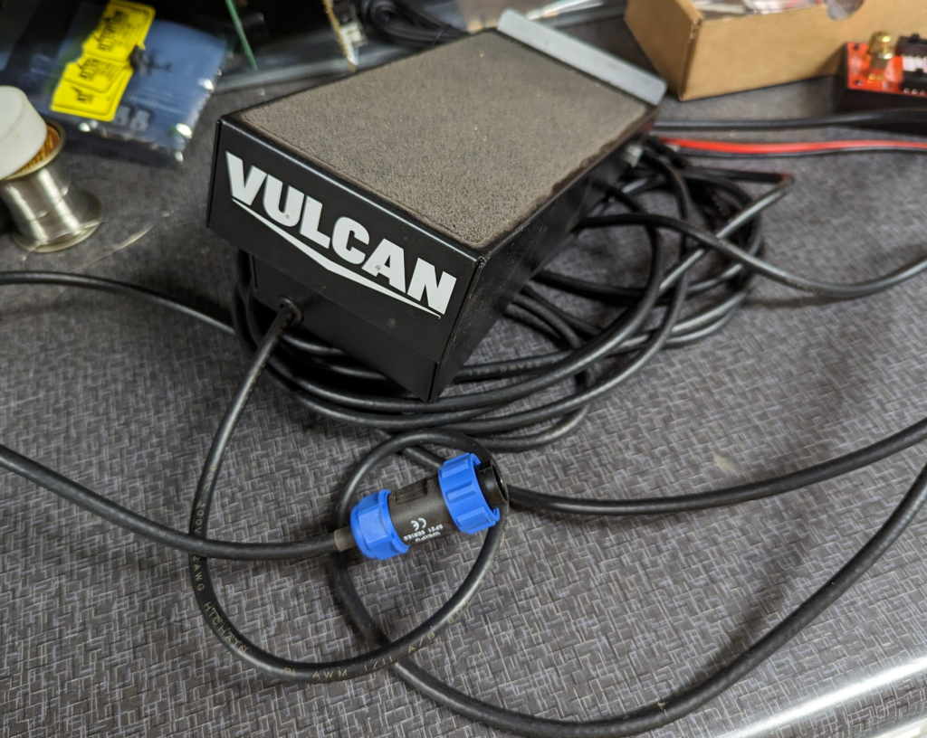
After chatting with Stephen Kraig on the podcast about hacking tig foot control pedals, I wondered what made the Vulcan brand foot pedal different. Most tig welding machines have either a 5 pin or 6 pin connector. Both of these types of foot pedals work the same. There is a simple SPST switch and then a potentiometer for how far the pedal travels. Farther the pedal goes down, the more amperage the tig welder will output. This requires 5 wires. The 6 pin connectors just have an unused pin.
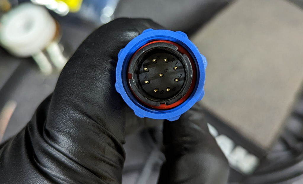
The Vulcan Tig Welder (from Harbor Freight) has a 9 pin connector for the foot pedal! What do these extra pins do? Or are they just unused as well?
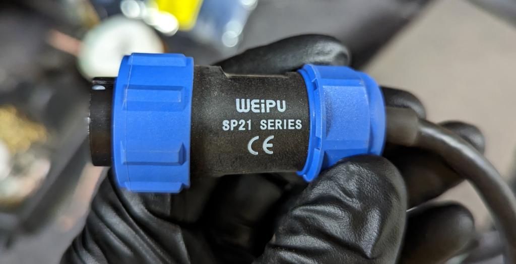
The connector is a Weipu SP21 series. Part Number: SP2110/P9 II 1. Looks like you can get these on AliExpress.
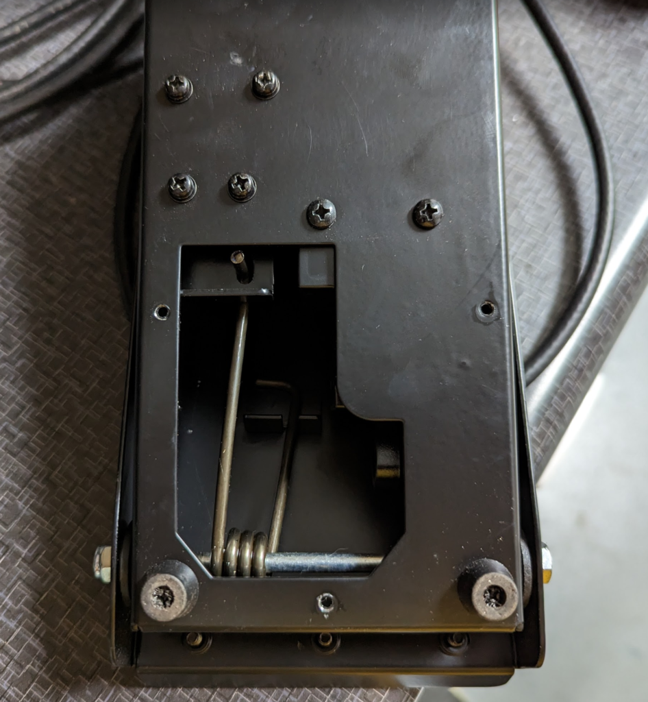
To open the foot pedal you need to remove this the panel on the bottom side with 3 screws. You will see the foot pedal spring inside.
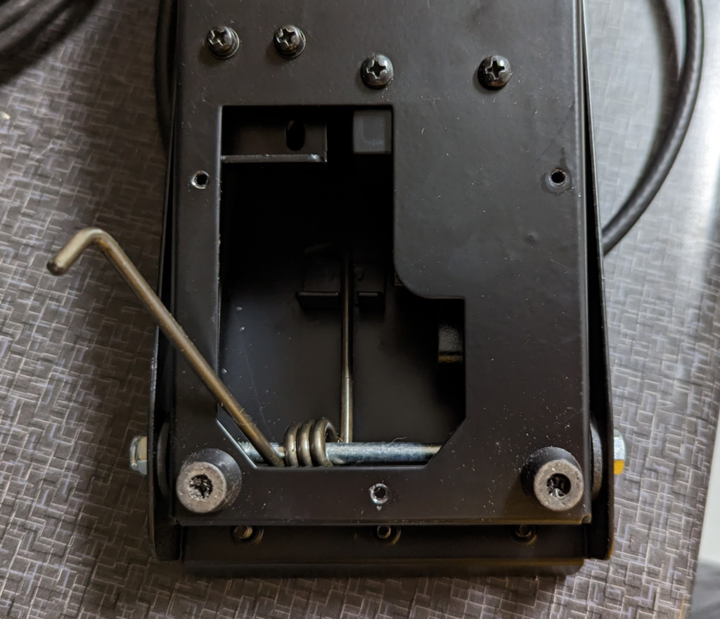
The spring needs to be pressed down and unhooked from the bottom side (side facing upwards during disassembly).
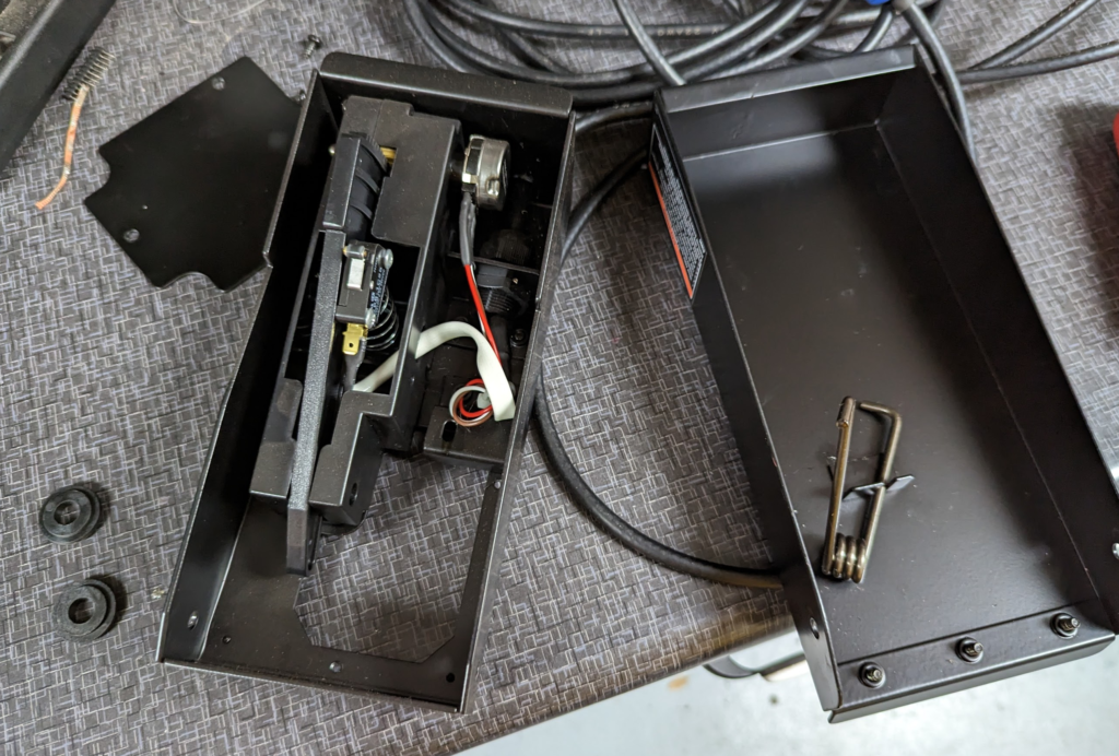
Then use a 10mm socket and wrench to remove the bolt used for the pivot and pull the case apart. There are two spacers on the bolt that locate the top part of the foot pedal with the bottom side along the pivot bolt.
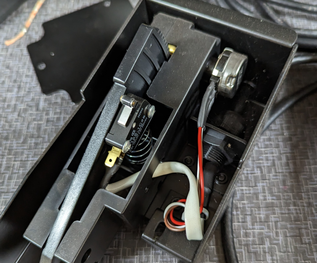
Inside the pedal we have a microswitch and a single potentiometer. Only 5 wires. Why Vulcan specified a 9 pin connector is lost to me. Would be interesting to see if there are any connections to the other 4 “unused” pins on the welder side…
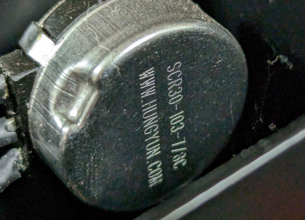
Potentiometer is a SCR30-103-7/8C by HungYun. 10K resistance.
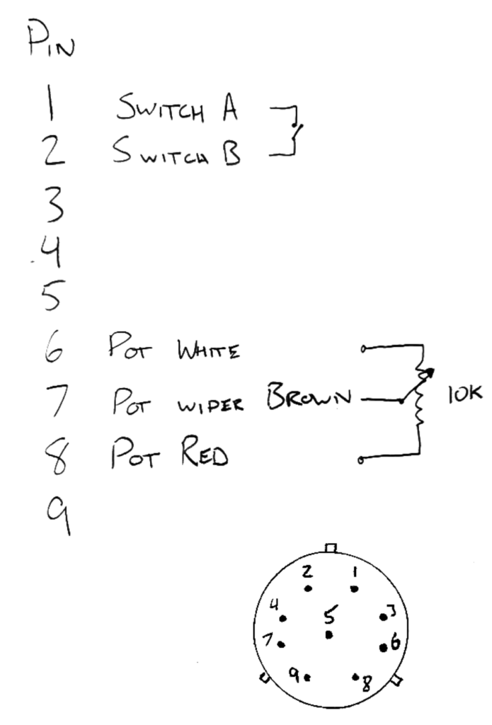
Here is a pinout for the connector.
I can probably get any finger controlled switch to work with this welder if its a 10K potentiometer.
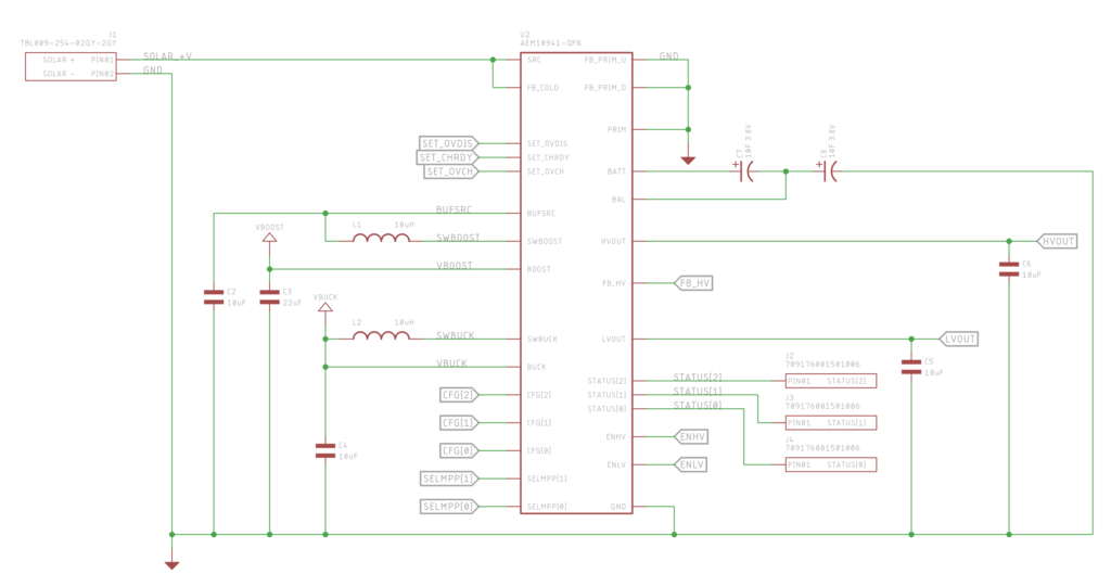
Just wrapped up the schematic side for the AEM10941 portion of the Cat Feeder Unreminder.
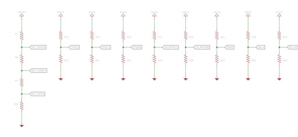
I broke out all the configuration pins to their own pullup / pulldown combos so I can experiment with voltage cutoffs for the super capacitors. Most likely leave most of configuration resistors unpopulated!
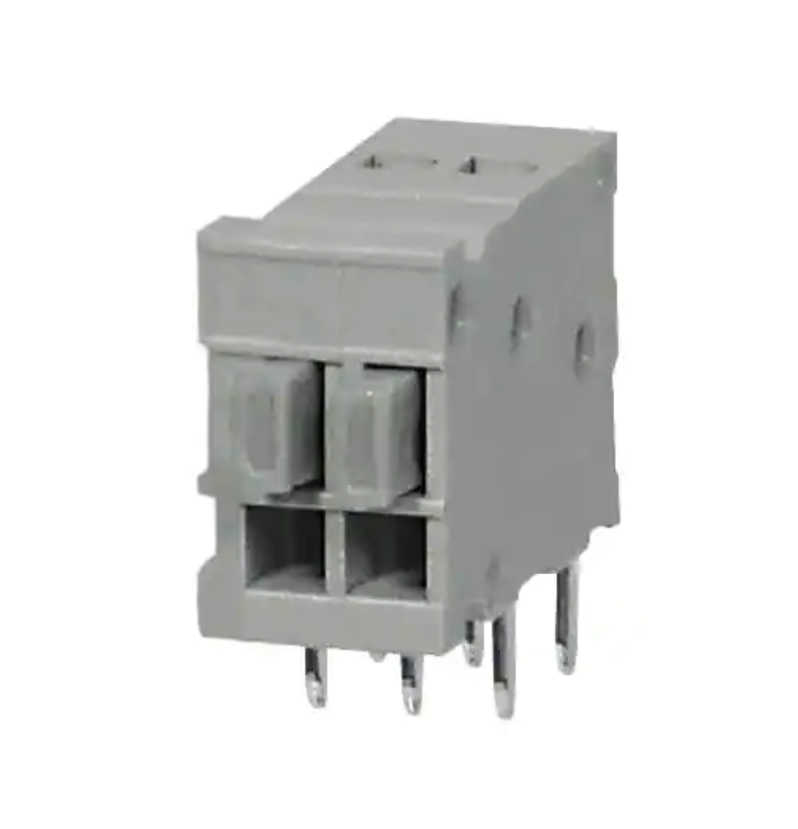
I found these really neat push button terminals that I am going to try to use for attaching the solar panel to the PCB. Part Number: TBL009-254-02GY-2GY