
Here is some analysis of the power lines and noise on the board. These measurements are taken with no load on the I/O besides what is built in on the board. Pins 29 and 28 run the EEPROM in I2C mode on boot to load the program into the Propeller.
With the Propeller doing nothing the board takes 7mA on the 5V line. Flipping all the ports as fast as the Propeller can do it at takes 20mA at 5V. Turning on all the cogs (8) and flipping the pins takes 94mA which is almost 1/5th the power budget of the USB spec (5V 500mA). During these measurements the board was powered with a dedicated lab power supply.
Here is the worst case noise analysis of the board. This is when all cogs are on and flipping all the I/O on and off to surge the power lines. Power is from my laptop USB port.
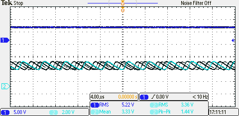
The top line is the 5V line from the USB port. This is expected to be fairly clean. The scope showed that it was relatively flat with with very little peak to peak action. This shows my laptops 5V line is a relatively good power source for the PDS.
The bottom line is the 3.3V line that is produced from the regulator on the PDS. As you can tell it is not level and oscillates a bit. The peak to peak is at 1.44V which is a very dirty power line. To fix this I added a 1uF capacitor to the 3.3V line which generated the following power signals.
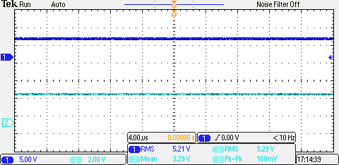
The 3.3V line now has a peak to peak of 160mV which is pretty good. I tried a 10uF capacitor to see if this could be improved but I received the same results. The PDS V1.2 will need to have a 1uF capacitor added to the board before production. This will be added via dead bug technique to the PDS V1.1 boards.